Agilent Technologies 5100 ICP-OES User Manual
Hide thumbs
Also See for 5100 ICP-OES:
- Site preparation manual (56 pages) ,
- User manual (6 pages) ,
- Service manual (312 pages)
Table of Contents
Advertisement
Advertisement
Table of Contents
Troubleshooting

Related Manuals for Agilent Technologies 5100 ICP-OES


Summary of Contents for Agilent Technologies 5100 ICP-OES
- Page 1 Agilent 5100 and 5110 ICP-OES User’s Guide...
- Page 2 Use, duplication or disclosure of Software is subject to The material contained in this Agilent Technologies’ standard © Agilent Technologies, Inc. 2014, document is provided “as is,” and is commercial license terms, and non- 2016, 2017, 2018 subject to being changed, without DOD Departments and Agencies of the notice, in future editions.
-
Page 3: Table Of Contents
Contents Contents 1. Safety Practices and Hazards General Verifying Safe State Plasma Heat, Vapors and Fumes Compressed Gas Hazards Electrical Hazards Other Precautions Warning Symbols CE Compliance Electromagnetic Compatibility EN55011/CISPR11 ICES/NMB-001 South Korean Class A EMC declaration 2. Introduction Site Preparation Requirements User Documentation Conventions Notes and tips... - Page 4 Contents Electrical Power Supplies Circuit breaker Other Connections Personal Computer Requirements Gas Supplies Exhaust system ICP-OES instrument cooling air supply Water Chiller System Drain Vessel 3. Installation Agilent ICP-OES Instrument Overview Instrument Status LED Color Coding Front Power On/Off Button ICP Expert Software Connecting ICP Expert software to the ICP-OES Performing a Detector and Instrument Calibration...
- Page 5 Contents SPS 3 Advanced Valve System (AVS) — AVS 4, AVS 6 and AVS 7 SVS 2 and SVS 2+ 5-channel Peristaltic Pump External Inlet Duct Adapter Air inlet dust filter Vapor Generation Accessory (VGA) Multimode Sample Introduction System (MSIS) Argon Humidifier IsoMist Programmable Temperature Spray Chamber 4.
- Page 6 Contents Instrument Idle State Setting the instrument to idle Turning off the instrument for long term shutdown 5. Maintenance and Troubleshooting Routine Cleaning Torch Cleaning Acid cleaning of the torch for aqueous or acid based samples Rinsing the torch Drying the torch Additional checks after cleaning Troubleshooting Spare Parts...
-
Page 7: Safety Practices And Hazards
Safety Practices and Hazards 1. Safety Practices and Hazards General Verifying Safe State Plasma Heat, Vapors and Fumes Compressed Gas Hazards Electrical Hazards Other Precautions Warning Symbols CE Compliance Electromagnetic Compatibility General Unless otherwise specified, statements in this manual apply to both the Agilent 5100 and 5110 ICP-OES instruments. -
Page 8: Verifying Safe State
Safety Practices and Hazards The safety practices described below are provided to help the user operate the instrument safely. Read each safety topic thoroughly before attempting to operate the instrument and always operate the spectrometer in accordance with these safety practices. Verifying Safe State The following general safety precautions must be observed during all phases of operation, maintenance and service of this instrument. -
Page 9: Heat, Vapors And Fumes
Safety Practices and Hazards The shielding around the torch compartment is designed to reduce UV, visible and RF radiation to safe levels while still permitting easy access to, as well as installation and viewing of, the torch. The spectrometer has an interlock system that is designed to extinguish the plasma if the mains supply fails, the handle on the torch compartment door is opened, or the torch loading handle is open. -
Page 10: Compressed Gas Hazards
Safety Practices and Hazards Compressed Gas Hazards All compressed gases (other than air) can create a hazard if they leak into the atmosphere. Even small leaks in gas supply systems can be dangerous. Any leak (except that of air or oxygen) can result in an oxygen-deficient atmosphere, which can cause asphyxiation. -
Page 11: Electrical Hazards
Safety Practices and Hazards Electrical Hazards The spectrometer system and some accessories contain electrical circuits, devices and components operating at dangerous voltages. Contact with these circuits, devices and components can cause death, serious injury or painful electric shock. Panels or covers which are retained by screws on the spectrometer and accessories may be opened only by Agilenttrained, Agilent-qualified or Agilentapproved field service engineers (unless specified otherwise). - Page 12 Safety Practices and Hazards The acid concentration in the sample that is measured varies, depending upon the digestion steps and acid types used. Instrument users should be aware of the hazards associated with use of the acids used for sample preparation and apply all necessary precautions including use of lab coats, safety goggles and other appropriate forms of personal protection.
-
Page 13: Warning Symbols
Safety Practices and Hazards Warning Symbols The following is a list of symbols that may appear in conjunction with warnings in this manual or on the spectrometer. The hazard they describe is also shown. The beginning of the warning text is noted by a warning icon: WARNING A triangular symbol indicates a warning. -
Page 14: Ce Compliance
Safety Practices and Hazards The following symbols appear on the instrument for your information. Mains power on Mains power off Single phase alternating current Protective ground terminal. Socket for Agilent accessory serial cable Socket for Ethernet LAN cable Socket for Agilent accessory USB cable Indication of correct orientation of gas filter flow direction CE Compliance Your Agilent ICP-OES instrument has been designed to comply with... -
Page 15: Electromagnetic Compatibility
Safety Practices and Hazards Proof that a product complies with these directives is indicated by: the CE Marking appearing on the rear of the product, and the documentation package that accompanies the product containing a copy of the Declaration of Conformity. The Declaration of Conformity is the legal declaration by Agilent that the product complies with the directives listed above, and shows the EN standards to which the product was tested to... -
Page 16: Ices/Nmb-001
Make sure that all peripheral devices are also certified. Make sure that appropriate cables are used to connect the device to peripheral equipment. Consult your equipment dealer, Agilent Technologies, or an experienced technician for assistance. Changes or modifications not expressly approved by Agilent Technologies could void the user’s authority to operate the... -
Page 17: Introduction
Introduction 2. Introduction Site Preparation Requirements User Documentation Specifications Electrical Power Supplies Other Connections Personal Computer Requirements Gas Supplies Exhaust system ICP-OES instrument cooling air supply Water Chiller System Drain Vessel Site Preparation Requirements Prior to receiving your instrument, you will have been provided with an Agilent 5100 and 5110 ICP-OES Site Preparation Guide, which describes the environmental and operating requirements of the ICP-OES system. -
Page 18: User Documentation
Introduction User Documentation You have been provided with the following documentation to help you set up and operate your Agilent ICP-OES system: This User’s Guide, with safety practices and hazards information, instructions for finding information about installing and maintaining the components of the ICP-OES and a brief operation overview. -
Page 19: Specifications
Introduction Specifications The Agilent ICP-OES instrument is suitable for indoor use only and is classified suitable under Equipment class I category. Temperature control For optimum analytical performance, it is recommended that the ambient temperature of the laboratory be between 20 and 25 °C (68 and 77 °F), and be held constant to within 2 °C ( 3.6 °F) throughout... -
Page 20: Other Connections
Introduction The mains power switch contains a 20 A circuit breaker, which is reset when the power switch is cycled. Other Connections IEEE 802.3, Ethernet LAN cable Personal Computer Requirements The recommended and minimum PC specifications can be found in the Agilent ICP-OES Site Preparation Guide. -
Page 21: Exhaust System
Introduction Table 3. Typical flow rates for the Agilent ICP-OES instruments Typical Flows Argon (with nitrogen purge gas) Measuring wavelengths Argon flow 16.7 L/min > 189 nm (poly boost off) Nitrogen flow 0.8 L/min Measuring wavelengths Argon flow 16.7 L/min <... -
Page 22: Water Chiller System
Introduction The air supply is used to cool the internal mechanical and electronic components of the instrument. Several of these assemblies contain parts prone to corrosion. The introduction of cooling air contaminated with high levels of acid vapors or other corrosive substances may cause damage to the instrument. -
Page 23: Drain Vessel
Introduction Drain Vessel The Agilent ICP-OES system needs a drain vessel for disposal of excess fluids from the spray chamber or autosampler. Suitable tubing is supplied with the spectrometer for use with inorganic solvents. When using organic solvents, different drain tubing that is suitable for the solvent in use will be required. - Page 24 Introduction This page is intentionally left blank. Agilent 5100 and 5110 ICP-OES User’s Guide...
-
Page 25: Installation
Installation 3. Installation Agilent ICP-OES Instrument Overview Instrument Status LED Color Coding Front Power On/Off Button ICP Expert Software Connecting ICP Expert software to the ICP-OES Performing a Detector and Instrument Calibration Hardware Components Replacement Torch Assembly and Disassembly Accessories The Agilent ICP-OES must be installed by an Agilent-trained, Agilent- qualified or Agilent-authorized field service engineer. -
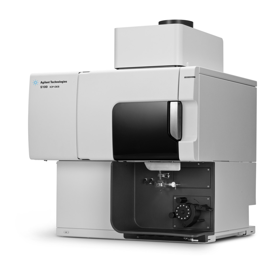
Page 26: Agilent Icp-Oes Instrument Overview
Installation Agilent ICP-OES Instrument Overview Figure 1. Front and side of the ICP-OES instrument 1. Exhaust 8. Torch loader handle 15. Torch compartment handle 2. Air inlet filter 9. Spray chamber 16. Water assembly 3. Cone and axial pre-optics 10. Nebulizer 17. - Page 27 Installation All connections of services to the ICP-OES instrument are made on the right side of the instrument, except for the mains power which is on the left side of the instrument. Remove the cover on the right side by hand to gain access to the Ethernet, accessory, water and gas connections.
-
Page 28: Instrument Status Led Color Coding
Installation Instrument Status LED Color Coding The instrument status indicator light on the front top right of the Agilent ICP-OES displays different colors to represent the status of the instrument: A green light indicates the following: The instrument and software are connected and are ready to ... -
Page 29: Icp Expert Software
Installation Green blinking slow (1 Hz). The mains power module is initializing and running through power up self-check, or is shutting off the instrument. Green blinking fast (4 Hz). Mains power module failed its initialization power-up self-check, instrument is unusable. The mains power supply is not adequate or the internal mains module needs to be replaced. -
Page 30: Connecting Icp Expert Software To The Icp-Oes
Installation For instructions on how to install your ICP Expert software, refer to the documentation provided with your software: ICP Expert Software Installation Instructions ICP Expert Software Installation Instructions for 21 CFR Part 11 Environments Once you have installed the appropriate software, connect the Ethernet cable, set the instrument IP address if necessary, and then perform the Detector Calibration and Wavelength Calibration. - Page 31 Installation Once the detector calibration is completed, the date and time of the last NOTE successful calibration will be displayed, confirming the detector measurement has been completed. Ensure a standard glass concentric nebulizer, a double pass spray chamber and the appropriate plasma torch (for radial or dual view) are installed.
-
Page 32: Saving And Viewing The Calibration Data
Installation Saving and viewing the calibration data The calibration data is stored in the Logs. To view the data, export the Logs. From the main ICP Expert window, click File > Logs > Export Logs. Save the zipped Log file. Open the .zip file to view the Log files. -
Page 33: Icp-Oes Torches
Installation ICP-OES torches Many of the ICP-OES torches are listed below, each with unique properties to suit a wide range of applications. Additional torches may be available. See the Agilent website for more information. Dual View Torches High solids Semi-volatile Parameter Standard Demountable... -
Page 34: Torch Assembly And Disassembly
Installation Torch Assembly and Disassembly The demountable torch models allow the outer/intermediate tube set to be separated from the base/injector for easier cleaning. Hot Surface WARNING The torch and torch compartment become warm during instrument operation and remain so for some time after the plasma has been switched off. Allow the plasma compartment to cool for at least five minutes before accessing the plasma compartment. -
Page 35: Torch Assembly
Installation Torch assembly To assemble the torch: Position the flat side of the torch securing ring so that it faces the top of the torch. Figure 4. Flat side of torch securing ring Slide the torch securing ring approximately 1/3 the way up the torch. - Page 36 Installation Figure 6. Torch inserted into torch body Position the torch so that the groove on the torch body aligns with the etch mark on the torch. Figure 7. Torch alignment Press the torch fully into the torch body and then press down on the torch securing ring.
-
Page 37: Torch Disassembly
Installation Torch disassembly To disassemble a two piece demountable torch: You may need a flat head screwdriver to loosen the securing ring if you cannot gently slide the torch out of the torch body by hand. Only use the screw driver to loosen the torch securing ring from the torch body if CAUTION you are unable to do so by hand. -
Page 38: Accessories
Installation Slide the torch securing ring off the torch. See Page 58 for the torch cleaning procedure. Accessories The following accessories may be available for use with your ICP-OES instrument: SPS 4 Autosampler SPS 3 Sample Preparation System Advanced Valve System (AVS) —... - Page 39 Installation SPS 4 See the instructions that came with the accessory for safety information and to prepare the SPS 4 for installation. The SPS 4 is compatible with a wide range of commercially available low-cost autoclavable sample racks. Sample contamination from airborne particles is eliminated and corrosive or toxic fumes are removed during sampling with the optional environmental enclosure.
-
Page 40: Svs 2 And Svs 2
Installation The integrated AVS 6 (6 port switching valve) and AVS 7 (7 port switching valve) increase sample throughput and decrease turnaround time and operating costs. The switching valve is positioned between the nebulizer and the peristaltic pump of the spectrometer. -
Page 41: External Inlet Duct Adapter
Installation External Inlet Duct Adapter The External Inlet Duct Adapter provides an attachment for ducting air into the air intake port, for use in labs with harsher environments. Air inlet dust filter The air inlet dust filter provides fine dust filtration of the air drawn into the air intake port. -
Page 42: Argon Humidifier
Installation Argon Humidifier The Argon Humidifier is commonly used when running aqueous samples with high dissolved solids or high dissolved salt content. When using the accessory, the nebulizer gas flow is passed through the humidifier to increase the water vapor in the gas. This has been found to be beneficial by reducing the build-up of salt and other dissolved solids in the sample introduction system. -
Page 43: Operation
Operation 4. Operation Analysis Checklist Turning On the Instrument and Software Preparing for Analysis Performing a Detector and Instrument Calibration Creating/Opening a Worksheet Developing a Method Running Samples Printing a Report Instrument Idle State This chapter provides a quick guide to getting the instrument set up and running samples. -
Page 44: Turning On The Instrument And Software
Operation Create/open a worksheet Develop a method Run samples Print a report Turning On the Instrument and Software Before starting the system, carefully read the Safety practices and hazards section at the front of this manual and ensure that the laboratory is set up according to the details specified in the Site Preparation Guide. -
Page 45: Running The Instrument From An Idle State
Operation 12 Plug the ICP-OES cable into the wall socket and set the mains power switch on the left side of the instrument to ‘On’. 13 Press the Power on/off button on the front of the instrument. The power on/off LED will display green when it is on. The ICP-OES is now in the idle state, which continually purges and thermostatically controls the polychromator. -
Page 46: Preparing For Analysis
Operation Preparing for Analysis To prepare for analysis: Click the Plasma button in the ICP Expert software. Alternatively, press F5 or choose Plasma on from the arrow under the Plasma button. The plasma ignition sequence will take up to 60 seconds to complete. If the NOTE plasma fails to ignite, refer to the Troubleshooting section in the Help for further information. -
Page 47: Creating/Opening A Worksheet
Operation Creating/Opening a Worksheet Creating a new worksheet To create a new worksheet, click New from the Start page or the File menu. A list of recently used files will be presented when creating a new worksheet from a template; otherwise you may Browse for more files. The ‘New From Template’... - Page 48 Operation Select the features and accessories on the Configuration page to be used during analysis. (Some features are only available in ICP Expert Pro software.) On the ‘Elements’ page, select the element(s) from the ‘Element’ drop-down box or type the element name or symbol and then perform one of the following: Click to add the primary wavelength for the selected...
-
Page 49: Running Samples
Operation Click Standards to enter the concentration of the elements in your standards and select whether to use other options such as Standard Additions or MultiCal. In addition, also select whether to use the blank in calibrations and whether to enable reslope. 10 Click Sequence to specify the number of samples, insert QC tests, select the solution type, edit the sample labels and end of run actions. -
Page 50: Printing A Report
Operation Printing a Report To print a report: Click Report on the toolbar or File > Report. Choose whether you want to print or preview the report or save the report as a PDF file. Previewing the report allows you to ensure that you have included all of the data you require. - Page 51 Operation When running organic samples it is recommended that the spray chamber be NOTE cleaned and dried thoroughly between analyses. Extinguish the plasma by clicking the Plasma Off icon, pressing SHIFT + F5 on the keyboard or choosing Plasma Off from the Analyze menu.
-
Page 52: Turning Off The Instrument For Long Term Shutdown
Operation Close the worksheet by clicking ‘Close’ from the ‘File’ menu but leave the ICP Expert software running. You may switch off the printer, monitor and any accessories if desired. Ensure that the Powersave option on your PC is disabled (this will prevent the shutdown of your hard disk). - Page 53 Operation Restarting the instrument to be ready for analysis again will take several hours due to the gas purge and polychromator thermal stabilization time. If the instrument is not going to be in use for a period of time the torch, cone, NOTE snout and torch compartment should be cleaned of any deposits, dirt or residue.
- Page 54 Operation This page is intentionally left blank. Agilent 5100 and 5110 ICP-OES User’s Guide...
-
Page 55: Maintenance And Troubleshooting
Maintenance and Troubleshooting 5. Maintenance and Troubleshooting Routine Cleaning Torch Cleaning Troubleshooting Spare Parts Technical Support This chapter includes the Agilent ICP-OES maintenance requirements that may be carried out by an operator. Any maintenance procedures not specifically mentioned in this chapter should be carried out only by Agilent-trained, Agilent-qualified or Agilent-authorized field service engineers. -
Page 56: Routine
Maintenance and Troubleshooting WARNING RF Hazard and Hot surfaces The plasma radiates dangerous levels of radio frequency (RF) energy. Exposure to the RF energy can cause severe skin damage and cataracts of the eyes, while close contact with the operating plasma can result in severe heat burns to the skin, and an electrical discharge which can jump a considerable distance and may cause death, severe electric shock or sub- surface skin burns. - Page 57 Maintenance and Troubleshooting Weekly Clean the torch Clean the cone Clean the snout Clean the spray chamber Clean the nebulizer Monthly Inspect the removable axial and radial pre-optics windows for cleanliness. Clean or replace as necessary. Clean the cooling air intake filter on top of your instrument ...
-
Page 58: Cleaning
Maintenance and Troubleshooting Cleaning Any spills in the sample compartment should be wiped up immediately. The user (or other authorized personnel) must perform the appropriate decontamination procedure if hazardous material is spilled on or inside the ICP-OES. The exterior surfaces of the ICP-OES should be kept clean. All cleaning should be done with a soft cloth. -
Page 59: Acid Cleaning Of The Torch For Aqueous Or Acid Based Samples
Maintenance and Troubleshooting Acid cleaning of the torch for aqueous or acid based samples See Page 34 for demountable torch disassembly instructions. Figure 12. Torch components where 1. Ball joint, 2. Gas ports, 3. Torch securing ring (demountable torch only), and 4. Torch outer tube To clean the torch: Soak the quartz parts of the torch in 50% aqua regia (1 part water to 1 part aqua regia) for at least 1 hour. - Page 60 Maintenance and Troubleshooting Two-piece demountable torches: The quartz outer tube set can be fully immersed in acid. See Figures 13B, 13C and 14. The injector can be inverted and dipped in the acid to just before the plastic base. Avoid acid contact with the seal where the quartz meets the plastic base. CAUTION Damage to the seals and torch body may occur.
-
Page 61: Rinsing The Torch
Maintenance and Troubleshooting Figure 14. Close up of torch placed in vessel, highlighting acid level relative to the plastic base Rinsing the torch To rinse one piece torches: Hold the torch with the ball joint connector at the top. Thoroughly flush the inside and outside of the torch with deionized water (18 MΩ.cm) using a wash bottle to direct the water stream. -
Page 62: Drying The Torch
Maintenance and Troubleshooting To rinse demountable torches: Thoroughly flush the inside and outside of the torch quartz components, including through the gas holes, with deionized water (18 MΩ.cm) using a wash bottle to direct the water stream. Drying the torch Oven drying is not recommended. -
Page 63: Additional Checks After Cleaning
Spare Parts For spare parts and consumables ordering information, refer to the Agilent Technologies website: www.agilent.com To replace the items listed below, you must use Agilent- manufactured parts, which can be ordered online from the Agilent website or through your local sales representative. -
Page 64: Technical Support
Maintenance and Troubleshooting Torch Air inlet filter (basic) Air inlet filter (dust filter) Axial pre-optic window Radial pre-optic window Spray chamber Nebulizer Peristaltic pump tubing Drain tubing Technical Support For technical support contact information, refer to the Agilent Technologies website for details: www.agilent.com Agilent 5100 and 5110 ICP-OES User’s Guide... - Page 66 In This Book The manual describes the following: Safety Practices and Hazards Introduction Installation Operation Maintenance and Troubleshooting © Agilent Technologies 2014, 2016, 2017, 2018 Printed in Malaysia 7/18 *G8010-90002* *G8010-90002* G8010-90002 Issue 6...