Table of Contents
Advertisement
Quick Links
Advertisement
Table of Contents

Related Manuals for ZyXEL Communications PM7516-R0


Summary of Contents for ZyXEL Communications PM7516-R0
- Page 1 User’s Guide PM7516-R0 / PM7116-R0 XGS-PON VoIP Bridge ONT with 10G LAN XGS-PON VoIP Bridge ONT Default Login Details Version 1.00 Edition 1, 10/2020 IP Address https:\\192.168.0.1 User Name admin Password See the device label Copyright © 2020 Zyxel Communications Corporation...
- Page 2 • Quick Start Guide The Quick Start Guide shows how to connect the Zyxel Device and get up and running right away. • More Information Go to support.zyxel.com to find other information on the Zyxel Device PM7516-R0 / PM7116-R0 User’s Guide...
-
Page 3: Document Conventions
Syntax Conventions • PM7516-R0 / PM7116-R0 may be referred to as “PM” in this guide. • Product labels, screen names, field labels and field choices are all in bold font. • A right angle bracket ( > ) within a screen name denotes a mouse click. For example, Network Setting >... -
Page 4: Table Of Contents
2.1.1 Accessing the Web Configurator ..................13 2.2 Web Configurator Layout ......................14 2.2.1 Navigation Panel ........................15 Part II: Technical Reference................17 Chapter 3 System Information ..........................18 3.1 System Info ............................18 Chapter 4 LAN ..............................20 4.1 Overview ............................20 PM7516-R0 / PM7116-R0 User’s Guide... - Page 5 10.1 Overview ............................32 10.2 Log Setting ............................. 32 Chapter 11 Firmware Upgrade ..........................33 11.1 Overview ............................33 11.2 Firmware ............................33 Chapter 12 Restore/Reboot ..........................35 12.1 Overview ............................35 12.2 Restore ............................35 12.3 Reboot ............................35 PM7516-R0 / PM7116-R0 User’s Guide...
- Page 6 13.2 Zyxel Device Access and Login ....................38 13.3 Internet Access ..........................39 Part III: Appendices ..................40 Appendix A Wall Mounting ......................41 Appendix B Legal Information ......................44 Appendix C Safety Warnings ......................45 PM7516-R0 / PM7116-R0 User’s Guide...
-
Page 7: Part I: User's Guide
User’s Guide... -
Page 8: Chapter 1 Introduction
Introduction 1.1 Overview PM7516-R0 and PM7116-R0 are Symmetric Passive Optical Network (XGSPON) VoIP Bridge Optical Network Terminals (ONT). The PM7516-R0 has one 10G Ethernet port and the PM7116-R0 has one 1G Ethernet port. 1.1.1 Network Bridge The Ethernet port on the Zyxel Device acts as a bridge. You can connect a switch or router to it. In the example figure below, the service provider (OLT) uses one physical fiber line to provide service for the Ethernet port on the Zyxel Device. -
Page 9: Managing The Zyxel Device
STATUS DESCRIPTION POWER Green The Zyxel Device is receiving power and finished booting. Blinking The Zyxel Device is under the process of power-on self-test (POST) and booting. System failure. Blinking Firmware upgrading. Not receiving power. PM7516-R0 / PM7116-R0 User’s Guide... -
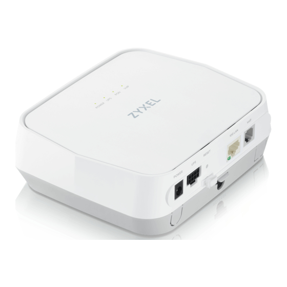
Page 10: Rear Panel
SIP account registered. 1.4.2 Rear Panel The following figure shows the rear panel where the connection ports are located. Figure 3 PM7516-R0 Rear Panel Figure 4 PM7116-R0 Rear Panel PM7516-R0 / PM7116-R0 User’s Guide... -
Page 11: Ups Port
Note: The main power and UPS cannot be used at the same time. Figure 5 UPS Port Pin Layout Table 4 UPS Port Pin Assignment UPS PORT VCC_12VDC UPS status: On battery UPS status: Battery missing PM7516-R0 / PM7116-R0 User’s Guide... -
Page 12: Reset Button
Press the RESET button for more than 5 seconds or until the POWER LED begins to blink. Wait for the POWER LED to turn solid green. At this point, the device is reset to factory default settings. Figure 6 Reset Button (PM7516-R0) PM7516-R0 / PM7116-R0 User’s Guide... -
Page 13: The Web Configurator
• Java permissions (enabled by default). 2.1.1 Accessing the Web Configurator The following uses PM7516-R0 screens as examples. Make sure your Zyxel Device hardware is properly connected (refer to the Quick Start Guide). Manually configure your computer’s IP address to 192.168.0.X (X represents any number from 2 to 254. -
Page 14: Web Configurator Layout
Chapter 2 The Web Configurator Figure 8 System Info Screen 2.2 Web Configurator Layout Figure 9 Screen Layout PM7516-R0 / PM7116-R0 User’s Guide... -
Page 15: Navigation Panel
WAN and LAN interfaces. Maintenance User Account User Account Use this screen to change the user password on the Zyxel Device. Time Setting Time Use this screen to change your Zyxel Device’s time and date. PM7516-R0 / PM7116-R0 User’s Guide... - Page 16 Restore to Use this screen to restore your Zyxel Device’s configuration (settings) or default default reset the factory default settings. Reboot Reboot Use this screen to reboot the Zyxel Device without turning the power off. PM7516-R0 / PM7116-R0 User’s Guide...
-
Page 17: Part Ii: Technical Reference
Technical Reference... -
Page 18: Chapter 3 System Information
This is the MAC (Media Access Control) address unique to your Zyxel Device. The MAC address uses six pairs of hexadecimal notation and follows an industry standard that ensures no other adapter has the same address. PM7516-R0 / PM7116-R0 User’s Guide... - Page 19 This field displays the current registration status of the SIP account. You have to register SIP accounts with a SIP server to use VoIP. This field displays the account number and service domain of the SIP account. PM7516-R0 / PM7116-R0 User’s Guide...
-
Page 20: Chapter 4 Lan
(packets sent to one computer) and broadcast packets (packets sent to every computer). Devices use the IGMP (Internet Group Management Protocol) network-layer protocol to establish membership in a multicast group. The Zyxel Device supports IGMP v1/IGMP v2. Select None to disable it. PM7516-R0 / PM7116-R0 User’s Guide... - Page 21 Select Enabled to enable IGMP snooping to forward group multicast traffic only to ports that are members of that group. Otherwise, select Disabled. Apply Click Apply to save your changes. Cancel Click Cancel to restore your previously saved settings. PM7516-R0 / PM7116-R0 User’s Guide...
-
Page 22: Chapter 5 Log
Warning: There is a warning condition on the system. Notice: There is a normal but significant condition on the system. Informational: The syslog contains an informational message. Debug: The message is intended for debug-level purposes. PM7516-R0 / PM7116-R0 User’s Guide... -
Page 23: Log
This field is a sequential value and is not associated with a specific entry. Time This field displays the time the log was recorded. Level This field displays the severity level of the log. Message This field states the reason for the log. PM7516-R0 / PM7116-R0 User’s Guide... -
Page 24: Chapter 6 Traffic Status
Select how often you want the Zyxel Device to update this screen. Set Interval Click this button to apply the new interval you entered in the Refresh Interval field. Stop Click Stop to stop refreshing statistics. Packets Sent PM7516-R0 / PM7116-R0 User’s Guide... -
Page 25: Lan Status
This indicates the number of bytes received on this interface. 6.3 LAN Status Click System Monitor > Traffic Status > LAN to open the following screen. This screen displays LAN interface statistics. Figure 15 System Monitor > Traffic Status > LAN PM7516-R0 / PM7116-R0 User’s Guide... - Page 26 This indicates the number of received packets on this interface. Error This indicates the number of frames with errors received on this interface. Drop This indicates the number of received packets dropped on this interface. PM7516-R0 / PM7116-R0 User’s Guide...
-
Page 27: Chapter 7 Voip Status
This field displays N/A if no number has ever dialed the SIP account. Number Last Outgoing This field displays N/A if the SIP account has never dialed a number. Number Call Status SIP Account This column displays each SIP account in the Zyxel Device. PM7516-R0 / PM7116-R0 User’s Guide... - Page 28 This field displays the SIP number that you use to receive calls on this phone port. Number Phone Status This field shows whether or the phone connected to the subscriber port is on-hook (ONHOOK) or off-hook (OFFHOOK). PM7516-R0 / PM7116-R0 User’s Guide...
-
Page 29: Chapter 8 User Account
Zyxel Device. Retype to Type the new password again for confirmation. Confirm Apply Click this to save your changes and to apply them to the Zyxel Device. Undo Click Undo to exit this screen without saving. PM7516-R0 / PM7116-R0 User’s Guide... -
Page 30: Chapter 9 Time Setting
Current Time This field displays the date and time of your Zyxel Device. Each time you reload this page, the Zyxel Device synchronizes the date and time with the time server. Time and Date Setup PM7516-R0 / PM7116-R0 User’s Guide... - Page 31 2 in the Time field because Germany's time zone is one hour ahead of GMT or UTC (GMT+1). Apply Click this to save your changes and to apply them to the Zyxel Device. Undo Click Undo to exit this screen without saving. PM7516-R0 / PM7116-R0 User’s Guide...
-
Page 32: Chapter 10 Log Setting
Enter the port number used by the syslog server. UDP Port Apply Click this to save your changes and to apply them to the Zyxel Device. Undo Click Undo to exit this screen without saving. PM7516-R0 / PM7116-R0 User’s Guide... -
Page 33: Chapter 11 Firmware Upgrade
The following table describes the labels on this screen. After you see the firmware updating screen, wait two minutes before logging into the Zyxel Device again. Table 16 Maintenance > Firmware Upgrade LABEL DESCRIPTION Upgrade Firmware Current This is the present firmware version. Firmware Version PM7516-R0 / PM7116-R0 User’s Guide... - Page 34 The Zyxel Device automatically restarts in this time causing a temporary network disconnect. In some operating systems, you may see the following icon on your desktop. Figure 21 Network Temporarily Disconnected After two minutes, log in again and check your new firmware version in the System Info screen. PM7516-R0 / PM7116-R0 User’s Guide...
-
Page 35: Chapter 12 Restore/Reboot
RESET button. 12.3 Reboot System restart allows you to reboot the Zyxel Device remotely without turning the power off. You may need to do this if the Zyxel Device hangs, for example. PM7516-R0 / PM7116-R0 User’s Guide... - Page 36 Chapter 12 Restore/Reboot Click Maintenance > Reboot. Click Reboot to have the Zyxel Device reboot. This does not affect the Zyxel Device's configuration. Figure 24 Maintenance > Reboot PM7516-R0 / PM7116-R0 User’s Guide...
-
Page 37: Chapter 13 Troubleshooting
Section 1.4.1 on page Check the hardware connections. Inspect your cables for damage. Contact the vendor to replace any damaged cables. Turn the Zyxel Device off and on. If the problem continues, contact the vendor. PM7516-R0 / PM7116-R0 User’s Guide... -
Page 38: Zyxel Device Access And Login
I can see the Login screen, but I cannot log into the Zyxel Device. Make sure you have entered the password correctly. See the cover page and device label for the default login name and associated password. The field is case-sensitive, so make sure [Caps Lock] is not PM7516-R0 / PM7116-R0 User’s Guide... -
Page 39: Internet Access
Check the hardware connections, and make sure the LEDs are behaving as expected. See the Quick Start Guide and Section 1.4.1 on page Turn the Zyxel Device off and on. If the problem continues, contact your vendor. PM7516-R0 / PM7116-R0 User’s Guide... -
Page 40: Part Iii: Appendices
Appendices Appendices contain general information. Some information may not apply to your device. -
Page 41: Appendix A Wall Mounting
Use screws and anchors of the size as shown below. Figure 25 Screws and Anchors Size Drill two holes in the wall with their centers either 85.5 mm or 60.0 mm apart. Figure 26 Drill Holes (85.5 mm Apart) PM7516-R0 / PM7116-R0 User’s Guide... - Page 42 Appendix A Wall Mounting Figure 27 Drill Holes (60.0 mm Apart) PM7516-R0 / PM7116-R0 User’s Guide...
- Page 43 Figure 28 Insert Screw Anchors and Screws Place the Zyxel Device so the wall mount holes line up with the screws. Slide the Zyxel Device down gently to fix it into place. Figure 29 Placing the Zyxel Device PM7516-R0 / PM7116-R0 User’s Guide...
-
Page 44: Appendix B Legal Information
The contents of this publication may not be reproduced in any part or as a whole, transcribed, stored in a retrieval system, translated into any language, or transmitted in any form or by any means, electronic, mechanical, magnetic, optical, chemical, photocopying, manual, or otherwise, without the prior written permission of Zyxel Communications Corporation. Published by Zyxel Communications Corporation. All rights reserved. -
Page 45: Appendix C Safety Warnings
• Conforme au 21 CFR 1040.10 et au 1040.11, à l'exception de la conformité au IEC60825 3e éd., comme décrit dans « Laser Notice No. 56 » du 8 mai 2019. • APPAREIL À LASER DE CLASSE 1 & CONFORME SELON IEC 60825-1:2014. PM7516-R0 / PM7116-R0 User’s Guide...