Siemens RUGGEDCOM RMC20 Installation Manual
Hide thumbs
Also See for RUGGEDCOM RMC20:
- Installation manual (34 pages) ,
- Installation manual (32 pages)

Related Manuals for Siemens RUGGEDCOM RMC20


Summary of Contents for Siemens RUGGEDCOM RMC20
- Page 1 Installation Manual SIMATIC NET Rugged Ethernet Switches RUGGEDCOM RMC20 Edition 04/2021 https://www.siemens.com...
- Page 2 Preface Introduction Installing the Device SIMATIC NET Communication Ports Rugged Ethernet Switches RUGGEDCOM RMC20 Technical Specifications Certification Installation Manual 04/2021 C79000-G8976-1007-10...
- Page 3 Note the following: WARNING Siemens products may only be used for the applications described in the catalog and in the relevant technical documentation. If products and components from other manufacturers are used, these must be recommended or approved by Siemens. Proper transport, storage, installation, assembly, commissioning, operation and maintenance are required to ensure that the products operate safely and without any problems.
-
Page 4: Table Of Contents
Accessing Documentation ....................... v Registered Trademarks ......................v Warranty ..........................v Training ..........................vi Customer Support ........................vi Contacting Siemens ........................ vi Introduction ........................... 1 Feature Highlights ....................1 Description ......................2 Required Tools and Materials ................. 3 Decommissioning and Disposal ................3 Supported Fiber Optic Cables ................ - Page 5 FCC ........................28 5.1.4 FDA/CDRH ......................28 5.1.5 ISED ........................28 5.1.6 ISO ........................28 5.1.7 ACMA ........................29 5.1.8 RoHS ........................29 5.1.9 Other Approvals ....................29 EMC and Environmental Type Tests ..............30 RUGGEDCOM RMC20 Installation Manual, 04/2021, C79000-G8976-1007-10...
-
Page 6: Preface
Warranty Siemens warrants this product for a period of five (5) years from the date of purchase, conditional upon the return to factory for maintenance during the warranty term. This product contains no user-serviceable parts. Attempted service by unauthorized personnel shall render all warranties null and void. -
Page 7: Training
Siemens Sales representative. Customer Support Customer support is available 24 hours, 7 days a week for all Siemens customers. For technical support or general information, contact Siemens Customer Support through any of the following methods: Online Visit http://www.siemens.com/automation/support-request... - Page 8 Preface Contacting Siemens 300 Applewood Crescent Concord, Ontario Canada, L4K 5C7 Telephone Toll-free: 1 888 264 0006 Tel: +1 905 856 5288 Fax: +1 905 856 1995 E-Mail ruggedcom.info.i-ia@siemens.com https://www.siemens.com RUGGEDCOM RMC20 Installation Manual, 04/2021, C79000-G8976-1007-10...
- Page 9 Preface Contacting Siemens viii RUGGEDCOM RMC20 Installation Manual, 04/2021, C79000-G8976-1007-10...
-
Page 10: Introduction
The RUGGEDCOM RMC20 was designed specifically to provide years of maintenance free operation for all your mission-critical, real-time control applications. To provide the utmost in reliability, the RUGGEDCOM RMC20 is tested to the most stringent international EMI and environmental standards for use in HV/MV electric utility substations and industrial manufacturing, process and control and intelligent transportation systems applications. -
Page 11: Description
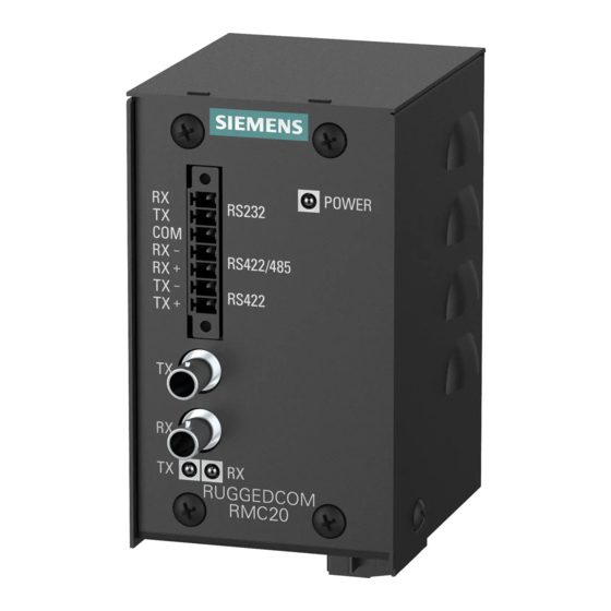
All power supplies CSA/UL 62368-1 approved for 85 °C (185 °F) operation Description The RUGGEDCOM RMC20 features various ports, controls and indicator LEDs on the display panel for connecting, configuring and troubleshooting the device. The display panel can be located on the rear, front or top of the device, depending on the mounting configuration. -
Page 12: Required Tools And Materials
RUGGEDCOM RMC20, refer to "Communication Ports (Page 17)". Required Tools and Materials The following tools and materials are required to install the RUGGEDCOM RMC20: Tools/Materials Purpose AC or DC power cord (16 AWG) For connecting power to the device. -
Page 13: Supported Fiber Optic Cables
1000Base-SX 10GBase-SR OM1 (62.5/125) — 1300 2000 — — OM2 (50/125) — 1300 2000 — — OM3 (50/125) 1500 — 1300 2000 — — OM4 (50/125) 3500 — 1300 2000 — — Laser optimized. RUGGEDCOM RMC20 Installation Manual, 04/2021, C79000-G8976-1007-10... -
Page 14: Installing The Device
This product contains no user-serviceable parts. Attempted service by unauthorized personnel shall render all warranties null and void. Changes or modifications not expressly approved by Siemens AG could invalidate specifications, test results, and agency approvals, and void the user's authority to operate the equipment. -
Page 15: General Procedure
If any item is missing or damaged, contact Siemens for assistance. Mounting the Device The RUGGEDCOM RMC20 is designed for maximum mounting and display flexibility. It can be equipped with adapters that allow it to be attached to a DIN rail or panel. -
Page 16: Mounting The Device On A Din Rail
2.3.1 Mounting the Device on a DIN Rail For DIN rail installations, the RUGGEDCOM RMC20 can be ordered with a DIN rail adapter preinstalled on the back of the chassis. Use the adapter to mount the device to a standard 35 mm (1.4 in) IEC/EN 60715 or TS35 DIN rail. - Page 17 Insert a flathead screwdriver into the slot of the sliding release and move it down. DIN Rail DIN Rail Adapter Figure 2.2 Removing the Device from a DIN Rail Swing the bottom of the device away from the DIN rail. Lift the device off the DIN rail. RUGGEDCOM RMC20 Installation Manual, 04/2021, C79000-G8976-1007-10...
-
Page 18: Mounting The Device To A Panel
Install the screw previously removed from the bottom of the panel adapter. Setting the Operating Mode To accommodate a wide array of serial devices, the RUGGEDCOM RMC20 is equipped with a MODE DIP switch located on the bottom of the device. The switch configures... -
Page 19: Serial-To-Fiber Conversion: Point-To-Point
2.4.1 Serial-to-Fiber Conversion: Point-to-Point The following illustrates the serial-to-fiber conversion mode of operation. Note In this example, the distance between the two RUGGEDCOM RMC20 devices is less than 5 km (3.1 mi). RUGGEDCOM RMC20 Installation Manual, 04/2021, C79000-G8976-1007-10... -
Page 20: Serial Standard Conversion
Installing the Device 2.4.2 Serial Standard Conversion RS232 Device RUGGEDCOM RMC20 RS485 Device/Network Figure 2.5 Serial-to-Fiber Point-to-Point Topology RS232 Device RS422 Device/Network Position State Notes Position State Notes RS232 <-> Fiber RS422 <-> Fiber Serial-to-Fiber Mode Serial-to-Fiber Mode Full Duplex Full Duplex... -
Page 21: Serial-To-Fiber Conversion: Loop Topology
Installing the Device 2.4.3 Serial-to-Fiber Conversion: Loop Topology RS232 Device RUGGEDCOM RMC20 RS485 Device/Network Figure 2.6 RS232 to RS485/422 Topology Position State Notes Serial Conversion Mode Half Duplex Fiber repeat OFF 9600 Baud In this mode of operation, RS232 voltage levels are converted to the appropriate RS485 or RS422 signalling levels depending on the DIP switch configuration. - Page 22 Installing the Device 2.4.3 Serial-to-Fiber Conversion: Loop Topology RS485 Slave (Repeat = ON) RUGGEDCOM RMC20 Multiple RUGGEDCOM RMC20 Devices RS485 Master (Repeat = OFF) Figure 2.7 Serial-to-Fiber Conversion in Example Optical Loop Topology Position State Notes RS485/422 <-> Fiber Serial-to-Fiber Mode Half Duplex Fiber repeat: Refer to Figure 2.7, “Serial-to-Fiber...
-
Page 23: Connecting Power
2.5 Connecting Power optical serial network because the RUGGEDCOM RMC20 utilizes a common optical signalling protocol for all serial standards. Connecting Power The RUGGEDCOM RMC20 supports a single integrated high AC/DC or low DC power supply Note • For 110/230 VAC rated equipment, an appropriately rated AC circuit breaker must be installed. - Page 24 The surge ground terminal is used as the ground conductor for all surge and transient suppression circuitry internal to the unit. Connect the ground terminal on the power source to the chassis ground terminal on the device. RUGGEDCOM RMC20 Installation Manual, 04/2021, C79000-G8976-1007-10...
-
Page 25: Connecting Dc Power
The surge ground terminal is used as the ground conductor for all surge and transient suppression circuitry internal to the unit. Connect the ground terminal on the power source to the chassis ground terminal on the device. RUGGEDCOM RMC20 Installation Manual, 04/2021, C79000-G8976-1007-10... -
Page 26: Communication Ports
Communication Ports The RUGGEDCOM RMC20 can be equipped with various types of communication ports to enhance its abilities and performance. Port 1 Port 2 Figure 3.1 Port Assignment Port Type RS232/RS485/RS422 Serial Terminal Multi-Mode Fiber Optic Port Fiber Optic Ports Fiber optic ports are available with ST (Straight Tip) connectors. Make sure the Transmit (Tx) and Receive (Rx) connections of each port are properly connected and matched to establish a proper link. -
Page 27: Serial Terminal
"Fiber Optic Port Specifications (Page 23)". Serial Terminal The RUGGEDCOM RMC20 is equipped with a seven-terminal Phoenix-style connector. This connector can accommodate one RS232 connection, and one RS485/422 connection. The following is the pin-out for the serial terminal: Name... - Page 28 3.2.1 RS232 Data Ports Note The RS232 port is intended for point-to-point applications only. In adherence to the EIA/TIA guidelines for RS232 communications, the following is recommended by Siemens: • Always use shielded cabling to minimize the effects of ambient electrical noise •...
-
Page 29: Rs485/422 Data Ports
120 Ohm resistor and a 10nF capacitor in series across the twisted pair). Note The RUGGEDCOM RMC20 features built-in pull-up and pull-down resistors. As such, external bias resistors are only recommended when connecting the RUGGEDCOM RMC20 to third-party serial devices that do not have built-in pull-up and pull-down resistors. - Page 30 Communication Ports 3.2.2 RS485/422 Data Ports 120Ω 10nF RUGGEDCOM RMC20 Device With Built-In Termination Common (Isolated Ground) Negative Positive Shield to Earth (Connected At a Single Point) RS485 Devices (32 Total) Figure 3.5 Recommended RS485 Wiring RUGGEDCOM RMC20 Installation Manual, 04/2021, C79000-G8976-1007-10...
- Page 31 Communication Ports 3.2.2 RS485/422 Data Ports RUGGEDCOM RMC20 Installation Manual, 04/2021, C79000-G8976-1007-10...
-
Page 32: Technical Specifications
3 dBm. To convert from peak to average, subtract 3 dBm. • Maximum segment length is greatly dependent on factors such as fiber quality, and the number of patches and splices. Consult a Siemens Sales associate when determining maximum segment distances. Data... -
Page 33: Operating Environment
Mechanical Specifications Weight 0.68 kg (1.5 lbs) Ingress Protection IP30 Enclosure 21 AWG Galvanized Steel Dimension Drawings Note All dimensions are in millimeters, unless otherwise stated. 92.8 80.1 73.7 62.2 58.4 70.7 Figure 4.1 Overall Dimensions RUGGEDCOM RMC20 Installation Manual, 04/2021, C79000-G8976-1007-10... - Page 34 Technical Specifications 4.5 Dimension Drawings 67.3 62.2 96.1 58.4 82.2 35.6 11.4 Figure 4.2 Panel Mount Dimensions RUGGEDCOM RMC20 Installation Manual, 04/2021, C79000-G8976-1007-10...
- Page 35 Technical Specifications 4.5 Dimension Drawings RUGGEDCOM RMC20 Installation Manual, 04/2021, C79000-G8976-1007-10...
-
Page 36: Certification
UL 62368-1 Information Technology Equipment – Safety – Part 1: General Requirements) 5.1.2 European Union (EU) This device is declared by Siemens AG to comply with essential requirements and other relevant provisions of the following EU directives: • EN 62368-1 Information Technology Equipment –... -
Page 37: Fcc
Certification 5.1.3 FCC The device is marked with a CE marking and can be used throughout the European community. A copy of the CE Declaration of Conformity is available from Siemens AG. For contact information, refer to "Contacting Siemens (Page vi)". -
Page 38: Acma
A copy of the Declaration of Conformity is available via Siemens Industry Online Support at https://support.industry.siemens.com/cs/ww/en/view/89855782. 5.1.8 RoHS This device is declared by Siemens AG to meet the requirements of the following RoHS (Restriction of Hazardous Substances) directives for the restricted use of certain hazardous substances in electrical and electronic equipment: •... -
Page 39: Emc And Environmental Type Tests
Certification 5.2 EMC and Environmental Type Tests EMC and Environmental Type Tests The RUGGEDCOM RMC20 has passed the following EMC and environmental tests. IEC 61850-3 Type Tests Test Description Test Levels Severity Levels Enclosure ± 8 kV 61000-4-2 Contact Enclosure Air ±... - Page 40 5 kV Ports Siemens specified severity level. IEEE 1613 EMC Immunity Type Tests Note The RUGGEDCOM RMC20 meets Class 2 requirements for an all-fiber configuration and Class 1 requirements for copper ports. Description Test Levels Enclosure Contact ± 8 kV Enclosure Air ±...
- Page 41 Certification 5.2 EMC and Environmental Type Tests Test Description Test Levels Severity Levels IEC 60255-21-1 Vibration 2 g @ 10-150 Hz Class 2 IEC 60255-21-2 Shock 30 g @ 11 ms Class 2 RUGGEDCOM RMC20 Installation Manual, 04/2021, C79000-G8976-1007-10...
- Page 42 Further Information Siemens RUGGEDCOM https://www.siemens.com/ruggedcom Industry Online Support (service and support) https://support.industry.siemens.com Industry Mall https://mall.industry.siemens.com Siemens AG Digital Industry Process Automation Postfach 48 48 90026 NÜRNBERG GERMANY...