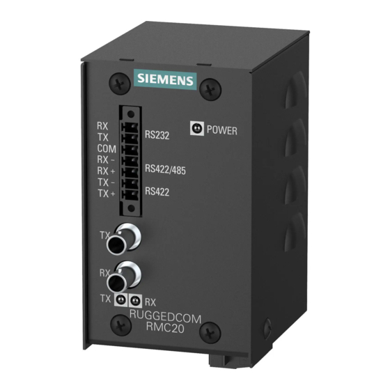
Siemens RUGGEDCOM RMC20 Installation Manual
Hide thumbs
Also See for RUGGEDCOM RMC20:
- Installation manual (34 pages) ,
- Installation manual (42 pages)

Related Manuals for Siemens RUGGEDCOM RMC20


Summary of Contents for Siemens RUGGEDCOM RMC20
- Page 1 Preface Introduction Installing the Device RUGGEDCOM RMC20 Communication Ports Technical Specifications Dimension Drawings Installation Guide Certification 6/2014 RC1007-EN-02...
- Page 2 Warranty Siemens warrants this product for a period of five (5) years from the date of purchase, conditional upon the return to factory for maintenance during the warranty term. This product contains no user-serviceable parts. Attempted service by unauthorized personnel shall render all warranties null and void.
-
Page 3: Table Of Contents
RUGGEDCOM RMC20 Installation Guide Table of Contents Table of Contents Preface ........................ Alerts ..............................v Accessing Documentation ........................v Training .............................. vi Customer Support ..........................vi Chapter 1 Introduction ......................1.1 Feature Highlights ........................1 1.2 Ports, Controls and Indicator LEDs ....................2 Chapter 2 Installing the Device .................... - Page 4 RUGGEDCOM RMC20 Table of Contents Installation Guide 4.4 Mechanical Specifications ......................20 Chapter 5 Dimension Drawings ..................Chapter 6 Certification ......................6.1 Agency Approvals ........................23 6.2 FCC Compliance ........................23 6.3 Industry Canada Compliance ...................... 23 6.4 EMI and Environmental Type Tests ..................... 24...
-
Page 5: Preface
Installation Guide Preface Preface This guide describes the RUGGEDCOM RMC20. It describes the major features of the device, installation, commissioning and important technical specifications. It is intended for use by network technical support personnel who are responsible for the installation, commissioning and maintenance of the device. -
Page 6: Training
Siemens sales representative. Customer Support Customer support is available 24 hours, 7 days a week for all Siemens customers. For technical support or general information, please contact Siemens Customer Support through any of the following methods: • Online Visit http://www.siemens.com/automation/support-request... -
Page 7: Introduction
RUGGEDCOM RMC20 Chapter 1 Installation Guide Introduction Introduction The RUGGEDCOM RUGGEDCOM series of media converters are industrially hardened and specifically designed to operate reliably in electrically harsh and climatically demanding environments. The RMC20 is a utility-grade, protocol-independent, serial-to-fiber and serial standards converter for all your serial communication requirements. -
Page 8: Ports, Controls And Indicator Leds
Chapter 1 RUGGEDCOM RMC20 Introduction Installation Guide Simple Plug and Play Operation • Simple, externally-accessible configuration • Transmit and receive data LED indicators for quick and easy troubleshooting • Fully integrated power supply connects directly to power source permanently for reliable maintenance-free... -
Page 9: Installing The Device
This product contains no user-serviceable parts. Attempted service by unauthorized personnel shall render all warranties null and void. Changes or modifications not expressly approved by Siemens Canada Ltd. could invalidate specifications, test results, and agency approvals, and void the user's authority to operate the equipment. -
Page 10: Mounting The Device On A Din Rail
Chapter 2 RUGGEDCOM RMC20 Installing the Device Installation Guide • Section 2.1.2, “Mounting the Device to a Panel” Section 2.1.1 Mounting the Device on a DIN Rail For DIN rail installations, the RMC20 can be equipped with a DIN rail bracket pre-installed on the back of the chassis. -
Page 11: Connecting Power
Ground. Note that all line-to-ground transient protection circuitry will be disabled. IMPORTANT! Siemens requires the use of external surge protection in VDSL applications where the line may be subject to surges greater than that for which the device is rated. Use the following specifications as a... -
Page 12: Connecting Ac Power
Chapter 2 RUGGEDCOM RMC20 Installing the Device Installation Guide • Clamping Voltage: 50 V to 200 V • Insertion Loss: < 0.1 dB at 10 MHz • Peak Surge Current: 10 kA, 8x20µs waveform The following sections describe how to connect power to the device: •... -
Page 13: Connecting Dc Power
RUGGEDCOM RMC20 Chapter 2 Installation Guide Installing the Device Using a braided wire or other appropriate grounding wire, connect the surge ground terminal to the chassis ground connection. The surge ground terminal is used as the ground conductor for all surge and transient suppression circuitry internal to the unit. -
Page 14: Configuring The Device
Chapter 2 RUGGEDCOM RMC20 Installing the Device Installation Guide Section 2.3 Configuring the Device The RMC20 can be configured using the Mode DIP switch located at the bottom of the enclosure. The DIP switches are shown in Figure 8. Using the switches one can change the operating mode of the RMC20. -
Page 15: Serial-To-Fiber Conversion: Point-To-Point
RUGGEDCOM RMC20 Chapter 2 Installation Guide Installing the Device Section 2.3.1 Serial-to-Fiber Conversion: Point-to-Point The following illustrates the serial-to-fiber conversion mode of operation. NOTE In this example, the distance between the two RMC20 devices is less than 5 km (3.1 mi). -
Page 16: Serial Standard Conversion
Chapter 2 RUGGEDCOM RMC20 Installing the Device Installation Guide Section 2.3.2 Serial Standard Conversion The following illustrates the connections for conversion between RS232 and RS485/422 devices. Figure 8: RS232 to RS485/422 Topology 1. RS232 Device 2. RMC20 3. RS485 Device/Network... - Page 17 RUGGEDCOM RMC20 Chapter 2 Installation Guide Installing the Device Figure 9: Serial-to-Fiber Conversion in Example Optical Loop Topology 1. RS85 Slave (Repeat = ON) 2. RMC20 3. Multiple RMC20 Devices 4. RS85 Master (Repeat = OFF) Position State Notes RS85/422 <-> Fiber...
- Page 18 RUGGEDCOM RMC20 Chapter 2 Installation Guide Installing the Device Serial-to-Fiber Conversion: Loop Topology...
-
Page 19: Communication Ports
RUGGEDCOM RMC20 Chapter 3 Installation Guide Communication Ports Communication Ports The RMC20 can be equipped with various types of communication ports to enhance its abilities and performance. To determine which ports are equipped on the device, refer to the factory data file available through . For more information on how to access the factory data file, refer to the User Guide for the RMC20. -
Page 20: Serial Terminal
Chapter 3 RUGGEDCOM RMC20 Communication Ports Installation Guide Figure 11: ST Port 1. Tx Connector 2. Rx Connector For specifications on the available fiber optic ports, refer to Section 4.2, “Fiber Optic Port Specifications”. To accommodate a wide array of fiber optical devices, the RMC20 is equipped with a mode selector switch located on the bottom of the device. -
Page 21: Rs232 Data Ports
RUGGEDCOM RMC20 Chapter 3 Installation Guide Communication Ports Name Mode Description RS232 Receive data RS232 Transmit data Shared common RS422/485 Receive data- RS422/485 Receive data+ RS485 Transmit data- Figure 12: Serial Terminal Pin Configuration RS485 Transmit data+ The following sections describe how to use the different modes available: •... -
Page 22: Rs485/422 Data Ports
Chapter 3 RUGGEDCOM RMC20 Communication Ports Installation Guide Name Description Receive Data Transmit Data SGND Signal Ground Figure 13: Phoenix-Style DB9 Connector Pin Configuration The RS232 data port has two modes of operations, but only one mode is active at any given time: •... - Page 23 RUGGEDCOM RMC20 Chapter 3 Installation Guide Communication Ports NOTE Transient protection is provided on all terminals. Lightning strikes and ground surge currents can cause large momentary voltage differences between ends of communication links. To ensure maximum reliability of the entire link, all equipment should have similar transient protection installed.
- Page 24 RUGGEDCOM RMC20 Chapter 3 Installation Guide Communication Ports RS485/422 Data Ports...
-
Page 25: Technical Specifications
To convert from peak to average, subtract 3 dBm. • Maximum segment length is greatly dependent on factors such as fiber quality, and the number of patches and splices. Consult a Siemens Sales associate when determining maximum segment distances. Connector... -
Page 26: Operating Environment
Chapter 4 RUGGEDCOM RMC20 Technical Specifications Installation Guide Section 4.3 Operating Environment Parameter Range Comments Ambient Operating Temperature -40 to 85 °C Measured from a 30 cm (12 in) radius surrounding the center of the (-40 to 185 °F) enclosure. -
Page 27: Dimension Drawings
RUGGEDCOM RMC20 Chapter 5 Installation Guide Dimension Drawings Dimension Drawings NOTE All dimensions are in millimeters, unless otherwise stated. 92.8 80.1 62.2 73.7 58.4 70.7 Figure 15: Overall Dimensions... - Page 28 Chapter 5 RUGGEDCOM RMC20 Dimension Drawings Installation Guide 67.3 62.2 96.1 58.4 82.2 35.6 11.4 Figure 16: Panel Mount Dimensions...
-
Page 29: Certification
RUGGEDCOM RMC20 Chapter 6 Installation Guide Certification Certification The RMC20 device has been thoroughly tested to guarantee its conformance with recognized standards and has received approval from recognized regulatory agencies. • Section 6.1, “Agency Approvals” • Section 6.2, “FCC Compliance”... -
Page 30: Emi And Environmental Type Tests
Chapter 6 RUGGEDCOM RMC20 Certification Installation Guide Section 6.4 EMI and Environmental Type Tests The RMC20 has passed the following EMI and environmental tests. IEC 61850-3 Type Tests Test Description Test Levels Severity Levels IEC 61000-4-2 Enclosure +/- 8 kV... - Page 31 5 kV (Fail-Safe Relay Output) DC Power ports 5 kV AC Power ports 5 kV Siemens specified severity level. IEEE 1613 (C37.90.x) EMI Immunity Type Tests NOTE The RMC20 meets Class 2 requirements for an all-fiber configuration and Class 1 requirements for copper ports.
- Page 32 Chapter 6 RUGGEDCOM RMC20 Certification Installation Guide Test Description Test Levels Severity Levels IEC 60068-2-2 Dry Heat Test Bd 85 °C (185 °F), 16 Hours IEC 60068-2-30 Humidity (Damp Test Db 95% (non-condensing), Heat, Cyclic) 55 °C (131 °F), 6 cycles...