Table of Contents
Advertisement
Quick Links
Advertisement
Table of Contents

Related Manuals for THORLABS MFC1


Summary of Contents for THORLABS MFC1
- Page 1 Motorized Microscope Focus Controller MFC1 User Guide...
- Page 2 The software may be used or copied only in accordance with the terms of those agreements. No part of this publication may be reproduced, stored in a retrieval system, or transmitted in any form or any means electronic or mechanical, including photocopying and recording for any purpose other than the purchaser's personal use without the written permission of Thorlabs, Inc.. Thorlabs, Inc.
-
Page 3: Table Of Contents
4.2.2. Preparation Chapter 5 Software 5.1. Microsoft Visual C++ Redistributable Package (2012) Installation 5.2. Microsoft .NET 4.5.2 Installation 5.3. Driver Installation 5.4. MFC1 GUI (Graphic User Interface) 5.5. Calibration Chapter 6 Maintaining the MFC1 6.1. Cleaning 6.2. Troubleshooting Chapter 7 Specifications 7.1. -
Page 4: Warning Symbols And Definitions
Chapter 1: MFC1 Warning Symbols and Definitions Chapter 1 Warning Symbols and Definitions Below is a list of warning symbols you may encounter in this manual or on your device. Symbol Description Direct Current Alternating Current Both Direct and Alternating Current... -
Page 5: Safety
WARNING DO NOT use the device for anything other than its intended use. If the device is used in a manner not specified by Thorlabs, the protection provided by the equipment may be impaired. WARNING DO NOT operate the unit without the Front Tube. Exposure to moving parts may lead to serious injury. -
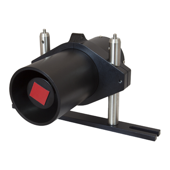
Page 6: Description
MFC1 is attached to the microscope. The MFC1 is computer controlled via the USB connection on the back of the controller. The unit comes with a GUI software package to control the motor, either via text box entry or a slider adjustment. -
Page 7: Front Panel Overview
Chapter 3: MFC1 Description 3.2. Front Panel Overview 3.3. Rear Panel Overview Page 4 TTN003537-D02... -
Page 8: Getting Started
MFC1 Getting Started Chapter 4 Getting Started 4.1. Unpacking and Inspection Open the package, and carefully remove the MFC1 and its accessories. The table lists the standard accessories shipped with the device. Name Quantity Motorized Focus Controller MFC1 Software CD... - Page 9 Peel off the liner on the adhesive tape, and mount the Front Tube on the unit. Slide the unit into the Gearhead Yoke , and press the unit onto the microscope knob. Note: Make sure the adhesive tape on the MFC1 Knob Cap and the microscope knob are in contact.
- Page 10 Replace the hex nut onto the Earth Ground Terminal. Insert the ground cable's banana plug into the optical table's threaded hole. Connect one end of the power supply to the MFC1 and the other end to a standard power outlet.
-
Page 11: Software
Microsoft Visual C++ Redistributable Package (2012) Installation Insert the MFC1 Software CD into the computer, and open the Driver folder. Double click the vcredist_x64 application to open the Microsoft Visual C++ Setup window. Select I agree to the license terms and conditions, and click Install. -
Page 12: Driver Installation
Microsoft .NET 4.5.2 software setup is complete. 5.3. Driver Installation Insert the MFC1 Software CD into the computer, and save the Application and Driver folder on your computer. Navigate to Device Manager>Other Devices. Right click on Trinamic Stepper Device and select Update Driver Software. - Page 13 Chapter 5: MFC1 Software Select Browse my computer for driver software, and browse to the Driver folder. Click Next. The Windows Security warning message appears. Click Install this driver software anyway. The Windows has successfully updated your driver software message appears. Click Close.
-
Page 14: Mfc1 Gui (Graphic User Interface)
Power cycle the USB and the MFC1. 5.4. MFC1 GUI (Graphic User Interface) The MFC1 GUI consists of a menu and control area. ● Menu: contains the File menu. Click File>Exit to exit from the Z Stepper Control window. ● Control Area: moves the Z stage and sets the Z parameters. -
Page 15: Calibration
Chapter 5: MFC1 Software Note: If you operate the MFC1 through ThorImageLS, use the Invert function to reverse the slider axis orientation for an inverted microscope. This option is not available with the standalone software. Note: The MFC1 software has a safety feature to prevent large, unintended movements of the objective through the GUI. -
Page 16: Maintaining The Mfc1
Chapter 6 Maintaining the MFC1 The MFC1 is not water resistant. The unit does not need regular maintenance. If you suspect a problem with the MFC1, please contact our nearest office (see Thorlabs Worldwide Contacts Chapter on Page 20 for details) for assistance from an applications engineer. - Page 17 Chapter 6: MFC1 Maintaining the MFC1 Problem Solution ● Power cycle the USB and the MFC1. ● Check the Z value. The software does not MFC1 not responding allow a movement beyond the hardware configure limits. Page 14 TTN003537-D02...
-
Page 18: Specifications
Chapter 7: MFC1 Specifications Chapter 7 Specifications 7.1. General Specifications Specifications Value 165.3 mm x 115.6 mm x 123.7 mm Module Dimensions (6.51" x 4.55" x 4.87") 1.36 kg Weight 40 Watt 24 VDC, 0~1.67 A Operating Voltage Max Motor Speed (controlled by... -
Page 19: Mechanical Drawing
Chapter 8: MFC1 Mechanical Drawing Chapter 8 Mechanical Drawing 1/4" (M6) Clearance Slot For Mounting To Base (2 Places) 7.87" 5.55" Ø2.47" (200.0 mm) (Ø62.7 mm) (140.9 mm) 6.14" (156.1 mm) 6.51" (165.3 mm) M4 Cap Screw 3 mm Hex... -
Page 20: Certifications And Compliance
Chapter 9: MFC1 Certifications and Compliance Chapter 9 Certifications and Compliance Page 17 Rev B, February 01, 2018... -
Page 21: Warranty
MFC1 Warranty Chapter 10 Warranty Thorlabs warrants that all products sold by Thorlabs will conform to the published specifications and shall be free from defects in material and workmanship under normal use, handling, and service. Thorlabs provides warranty for a period of one year. -
Page 22: Regulatory
Waste Treatment is Your Own Responsibility If you do not return an “end of life” unit to Thorlabs, you must hand it to a company specialized in waste recovery. Do not dispose of the unit in a litter bin or at a public waste disposal site. -
Page 23: Thorlabs Worldwide Contacts
Chapter 12: MFC1 Thorlabs Worldwide Contacts Chapter 12 Thorlabs Worldwide Contacts For technical support or sales inquiries, please visit us at www.thorlabs.com/contact for our most up-to- date contact information. USA, Canada, and South America UK and Ireland Thorlabs, Inc. Thorlabs Ltd.