
Related Manuals for Comelit Simplebus1 Ultra UT1010


Summary of Contents for Comelit Simplebus1 Ultra UT1010
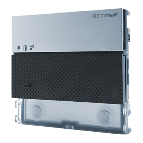
- Page 1 TECHNICAL MANUAL Simplebus1 Ultra audio module Art. UT1010 Passion.Technology.Design.
-
Page 2: Warning
• any purpose other than the intended use, • failure to observe the indications and warnings contained in this Manual / Instruction sheet. Comelit Group S.p.A. reserves the right to change the information provided in this Manual / Instruction Sheet at any time and without prior notice. -
Page 3: Table Of Contents
Table of contents Warning .................... 2 Description ..................4 UT1010 ......................4 Technical specifications ..............6 Art. UT1010 ....................6 Installation ..................7 Flush-mounted installation composition table ........7 Surface-mounted installation composition table ........7 Flush-mounted installation ............. 8 Removing nameplates (2A) / module (2B) ..........9 Installation with side-by-side boxes .............10 Wall-mounted installation ............. -
Page 4: Description
Description UT1010 Audio module for Ultra entrance panel, Simplebus1 system. To be used in systems with power supply unit art. 1595 and art. 4888C. Easy to install and simple to configure, thanks to the smart programming of call buttons. Twilight sensor for automatic nameplate backlighting switch-off during daylight hours. Omnidirectional digital microphone and double loudspeaker for high-fidelity audio. - Page 5 3. 4. 5. 13. 14. 1. Indicator LEDs 12. Terminal block for connection: call sent (green) / system busy (red) RTE programmable RTE (local lock-release input) or DO input (door open indication) lock-release enabled GND RTE or DO input reference negative IF door lock reference negative communication enabled NO NC COM relay contacts...
-
Page 6: Technical Specifications
Technical specifications Art. UT1010 GENERAL DATA Type Modular Product height (mm) Product width (mm) Product depth (mm) Product weight (g) Product colour Black RAL9005, Transparent, Aluminium Coating material type Polycarbonate, Aluminium alloy Flush mounting Yes, with specific accessory Surface mounting Yes, with specific accessory COMPATIBLE SYSTEMS Simplebus 2 audio/video... -
Page 7: Installation
Installation The entrance panel is available in flush-mounted or surface-mounted variants: Flush-mounted installation composition table A = Flush-mounted box B = Rain shield C = Flush-mounted module holder with finishing frame 3110/1 3110/2 3110/3 3110/4 3110/1A 3110/2A 3110/3A 3110/4A UT9181 UT9182 UT9184H UT9183... -
Page 8: Flush-Mounted Installation
Flush-mounted installation Optional Optional BLACK... -
Page 9: Removing Nameplates (2A) / Module (2B)
CLACK! CLACK! CLACK! CLACK! CLACK! CLACK! The button has a nameplate which can be written on (A); alternatively, an adhesive label can be applied (B). The total thickness of the nameplate + adhesive label MAX 0,2 mm must not exceed 0.2 mm. You can visit the website pro.comelitgroup.com to download the PDF to print the entrance panel name cards, using the MAX 0,2 mm... -
Page 10: Installation With Side-By-Side Boxes
Installation with side-by-side boxes Before installing the boxes in the wall, fit the spacers. -
Page 11: Wall-Mounted Installation
Wall-mounted installation Optional Optional BLACK... -
Page 12: Removing Nameplates (2A) / Module (2B)
CLACK! CLACK! CLACK! CLACK! CLACK! CLACK! The button has a nameplate which can be written on (A); alternatively, an adhesive label can be applied (B). The total thickness of the nameplate + adhesive label MAX 0,2 mm must not exceed 0.2 mm. You can visit the website pro.comelitgroup.com to download the PDF to print the entrance panel name cards, using the MAX 0,2 mm... -
Page 13: Installation With Side-By-Side Boxes
Installation with side-by-side boxes... -
Page 14: Connections
Connections UT1010 connections AUDIO DOOR-ENTRY 1595 SYSTEM RISER 120-230 V SE NO NC UT1010 Max 20 m. Local door-opener button. Variants Variant for using the outdoor entrance panel relay Variant for using a safety door lock 1595 1595 120-230 V 120-230 V 12V/24V AC-DC... -
Page 15: Module Connection
Module connection Connection of button modules Art. UT9200 AUDIO DOOR-ENTRY 1595 SYSTEM RISER 120-230 V BLACK SE NO NC UT1010 UT9200 Max 20 m. Local door-opener button. Connection of Touchscreen module Art. UT9270 AUDIO DOOR-ENTRY 1595 SYSTEM RISER 120-230 V SE NO NC UT1010 UT9270... -
Page 16: Connection Of Number Keypad Module Art. Ut9279M
Connection of number keypad module Art. UT9279M AUDIO DOOR-ENTRY 1595 SYSTEM RISER 120-230 V SE NO NC UT1010 UT9279M Max 20 m. Local door-opener button. -
Page 17: Programming
Programming For correct programming, follow the instructions below in order Configure button type Address button modules III. Program call addresses Configuring the button type to maintain during normal operation (single/dual) DIP 6: configuring button type: Single button (DIP6 ON). default Dual button (DIP6 OFF, default). -
Page 18: Smart Programming Of Consecutive Addresses
Smart programming of consecutive addresses default DIP 6: configuring button type: Single button (DIP6 ON). Dual button (DIP6 OFF, default). Set the address of the apartment you wish to call (for example: 1) using the DIP-switches (see “Addressing table” 1 2 3 4 S1 S2 1 2 3 4 example:... -
Page 19: Programming Of Specific Addresses
Programming of specific addresses default DIP 6: configuring button type: Single button (DIP6 ON). Dual button (DIP6 OFF, default). Set the address of the apartment you wish to call (for example: 25) using the DIP-switches (see “Addressing table” 1 2 3 4 S1 S2 1 2 3 4 example:... -
Page 20: Special Programming Via Dip Switch
Special programming via DIP Switch S1 S2 Take note of the DIP-switch settings 1. Set the dip switches in accordance with 1 2 3 4 the function you wish to program (see “Special programming table”). 2. Press the confirm button. S1 S2 Reset the configuration of the DIP-switches... -
Page 21: Special Programming Table
Special programming table CODE DIP SWITCHES ON FUNCTIONS Audio-visual messages 1,2,7,8 Hebrew 3,7,8 Polish 1,3,7,8 Catalan 2,3,7,8 Galician 1,2,3,7,8 Basque 2,3,4,7,8 Danish 1,2,3,4,7.8 Norwegian 1,2,5,7,8 Swedish 1,2,3,5,7.8 Italian 4,5,7,8 French 1,4,5,7,8 Spanish 2,4,5,7,8 Dutch 1,2,4,5,7.8 Greek 3,4,5,7,8 English 1,3,4,5,7.8 German 2,3,4,5,7.8 Portuguese 2,4,7,8... - Page 22 2,4,5,8 System busy signalling time: 10 sec (default) 1,2,4,5,8 System busy signalling time: 300 sec 1,2,3,4,6,7,8 Confirmation tone on user call = enabled (default) 5,6,7,8 Confirmation tone on user call = disabled 1,2,5,6,7.8 Reset wait time (after hang-up or after lock-release): 10 sec (default) 3,5,6,7,8 Reset wait time (after hang-up or after lock-release): 1 sec 5,7,8...
-
Page 23: Twilight Sensor
Twilight sensor Button backlighting management The twilight sensor is in AUTO mode by default: the LEDs light up at night and switch off during the day. To change the setting to ON (LEDs always on) or OFF Take note of the DIP-switch (LEDs always off), proceed settings as follows:... -
Page 24: Checking Twilight Sensor Operation
S1 S2 Reset the configuration of the DIP-switches Checking twilight sensor operation S1 S2 S1 S2 5 sec If it is daytime and you want to check AUTO mode operation for the twilight sensor, you can proceed as follows: 1. Enter programming mode 2. -
Page 25: Adjusting The Brightness Of The Button Leds
Adjusting the brightness of the button LEDs S1 S2 Take note of the DIP-switch settings 1. Enable brightness control 2. Set the desired 1 2 3 4 function (code 161) and press the confirm cod. 161 programming button 1 2 3 4 Press a button repeatedly for each module to change... -
Page 26: Light-Me Function
Light-me function Thanks to this function, button backlighting is only enabled on the user’s request, by pressing the LIGHT-ME button on the audio/video module; this saves energy and reduces light pollution. Backlighting management for this button depends on the twilight sensor setting. It is in AUTO mode by default: the LEDs light up at night and switch off during the day. -
Page 27: Replacing The Audio Module With Programming Restore Backup
Replacing the audio module with programming restore backup If the audio or audio/video module is replaced, the following instructions must be observed. The procedure should be completed within one hour of removal of the old module. Take note of the DIP-switch settings 1. -
Page 28: Configuring Via Pc
Configuring via PC All device configurations can be performed via PC and ViP Manager configuration software, available to download free of charge from pro.comelitgroup.com (See programming manual) For example: • programming call addresses for the buttons • activating audiovisual indications •... -
Page 29: Addressing Table
Addressing table Dip switch Code 1,2,3,4,5 1,3,4,5,6 1,2,4,5,7 1,4,5,6,7 1,2,3,5,8 1,3,5,6,8 1,2,5,7,8 2,3,4,5,6 3,4,5,7 2,4,5,6,7 4,5,8 2,3,5,6,8 3,5,7,8 1,2,3,4,5.6 1,3,4,5,7 1,2,4,5,6.7 1,4,5,8 1,2,3,5,6.8 1,3,5,7,8 2,3,4,5,7 3,4,5,6,7 2,4,5,8 4,5,6,8 2,3,5,7,8 1,2,6 1,2,3,4,5.7 1,3,4,5,6.7 1,2,4,5,8 1,4,5,6,8 1,2,3,5,7.8 2,3,4,5,6.7 3,4,5,8 2,4,5,6,8 4,5,7,8 1,2,3 1,3,6 1,2,7 1,6,7... - Page 30 C E R T I F I E D M A N A G E M E N T S Y S T E M S w w w . c o m e l i t g r o u p . c o m Via Don Arrigoni, 5 - 24020 Rovetta (BG) - Italy...