Table of Contents
Advertisement
Quick Links
Advertisement
Table of Contents

Related Manuals for Datalogic Matrix 220


Summary of Contents for Datalogic Matrix 220
- Page 1 Matrix 220™ PRODUCT REFERENCE GUIDE Image Based Reader...
- Page 2 Electronic versions of this document may be downloaded from the Datalogic website (www.datalogic.com). If you visit our website and would like to make comments or suggestions about this or other Datalogic pub- lications, please let us know via the "Contact" page.
-
Page 3: Table Of Contents
GENERAL VIEW .......................XIII RAPID CONFIGURATION....................1 Step 1 - Connect the System .................... 1 CBX100/CBX500 Pinout for Matrix 220 ....................2 Step 2 - Mount and Position the Reader ................3 Step 3 - Aim and Autofocus the Reader ................5 Step 4 - X-PRESS Configuration .................. - Page 4 ID-NET Connection Diagrams ......................78 Auxiliary RS232 Interface ....................81 Inputs ..........................82 External Trigger Input Connections Using Matrix 220 Power ............83 External Trigger Input Connections Using External Power ............85 Input 2 Connections Using Matrix 220 Power .................86 Input 2 Connections Using External Power ..................87 Input 3 Connections (CBX500 Only) ....................
- Page 5 7 mm Models (38°Horizontal View Angle) ..................108 12 mm Models (24° Horizontal View Angle) ..................110 Reading Diagrams ......................112 Matrix 220 (7 mm models) 1D Codes .....................113 Matrix 220 (7 mm models) 2D Codes .....................115 Matrix 220 (12 mm models) 1D Codes ...................116 Matrix 220 (12 mm models) 2D Codes ...................118...
- Page 6 Com and Trigger Connector for PoE Models ..............184 On-Board Ethernet Connector ..................185 Standard Models ..........................185 Power over Ethernet (PoE) Models ....................186 ID-NET Network Termination ..................186 Inputs .......................... 187 Outputs ........................187 User Interface - Serial Host ..................189 GLOSSARY......................190 MATRIX 220...
-
Page 7: Preface
TECHNICAL SUPPORT Support Through the Website Datalogic provides several services as well as technical support through its website. Log on to (www.datalogic.com). For quick access, from the home page click on the search icon , and type in the name of the product you’re looking for. -
Page 8: Reseller Technical Support
PREFACE Reseller Technical Support An excellent source for technical assistance and information is an authorized Datalogic reseller. A reseller is acquainted with specific types of businesses, application software, and computer systems and can provide individualized assistance. viii MATRIX 220... -
Page 9: Compliance
Datalogic commercial reference contacts. Since April 20th, 2016 the main European directives applicable to Datalogic products require inclusion of an adequate analysis and assess- ment of the risk(s). This evaluation was carried out in relation to the applicable points of the standards listed in the Declaration of Conformity. -
Page 10: Fcc Compliance
According to EN 62471:2008, using limits stated in the directive 2006/25/EC, all models are exempt (Risk Group 0), except model Matrix 220 3U2-01U which is Risk Group 3. for Matrix 220 3U2-01U, the measure of the NEAR UV radiation power com-... -
Page 11: Handling
HANDLING The Matrix 220 is designed to be used in an industrial environment and is built to with- stand vibration and shock when correctly installed, however it is also a precision prod- uct and therefore before and during installation it must be handled correctly to avoid damage. - Page 12 HANDLING • do not weld the reader into position which can cause electrostatic, heat or reading window damage. • do not spray paint near the reader which can cause reading window damage. MATRIX 220...
-
Page 13: General View
GENERAL VIEW Standard Model PoE Model Figure 1 - General View of DPM Models 1. Reading Window 7. X-PRESS Interface 2. Mounting Holes (2) 8. Ethernet Connector 3. Power On LED 9. - Page 14 2. Mounting Holes (2) 8. Ethernet Connector 3. Power On LED 9. Power, COM, I/O Connector 4. Ethernet Connection LED 10. Power Over Ethernet Connector 5. 90° Rotating Connector Block 11. COM, Trigger Connector 6. Accessory Window Cover MATRIX 220...
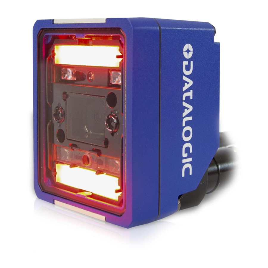
- Page 15 DPM Models Standard Models Figure 3 - Reading Window Details 1. Lens 5. Non Polarized Illuminator 2. LED Aiming System 6. Polarized Illuminator 3. Red Spot (No Read) 7. Diffused Illuminators 4.
- Page 16 Figure 4 - Reading Window Details for High Power Illuminator Models 1. Lens 5. Non Polarized Illuminator 2. LED Aiming System 6. Polarized Illuminator 3. Red Spot (No Read) 7. Standard Illuminators (Top/Bottom) 4. Green Spot (Good Read) 8. Central HP Illuminators MATRIX 220...
- Page 17 Figure 5 - X-PRESS Interface Details NORMAL X-PRESS OPERATION CONFIGURATION Ready Learn Good Setup Trigger Test Status Push-button xvii PRODUCT REFERENCE GUIDE...
- Page 18 GENERAL VIEW xviii MATRIX 220...
-
Page 19: Rapid Configuration
CAB-DSxx-S Matrix 220 Alone PG6000 Ethernet Interface Auxiliary Serial Interface (RS232 - Data Monitor) External Trigger (for One Shot or Phase Mode) Figure 6 - Matrix 220 in Stand Alone Layout PRODUCT REFERENCE GUIDE... -
Page 20: Cbx100/Cbx500 Pinout For Matrix 220
RAPID CONFIGURATION CBX100/CBX500 Pinout for Matrix 220 The table below gives the pinout of the CBX100/CBX500 terminal block connectors. Use this pinout when the Matrix 220 reader is connected by means of the CBX100/CBX500: GROUP LABEL DESCRIPTION Power Supply Input Voltage +... -
Page 21: Step 2 - Mount And Position The Reader
STEP 2 - MOUNT AND POSITION THE READER STEP 2 - MOUNT AND POSITION THE READER 1. To mount the Matrix 220, use the mounting brackets to obtain the most suitable position for the reader. The most common mounting configuration is shown in the figure below. - Page 22 Chapter 6, Reading Features tance your reader should be positioned at. Rapid Configuration of the Matrix 220 reader can be made either through the X-PRESS interface (steps 3-4) which requires no PC connection, or by using the DL.CODE Configuration Program (steps 5-6). Select the pro- NOTE cedure according to your needs.
-
Page 23: Step 3 - Aim And Autofocus The Reader
STEP 3 - AIM AND AUTOFOCUS THE READER STEP 3 - AIM AND AUTOFOCUS THE READER Matrix 220 provides a built-in LED aiming system to aid reader positioning. The autofo- cus feature is also incorporated into this function. The aiming system is accessed through the X-PRESS Interface. -
Page 24: Step 4 - X-Press Configuration
RAPID CONFIGURATION STEP 4 - X-PRESS CONFIGURATION Once Matrix 220 is focused at the correct reading distance, you must configure it for optimal code reading relative to your application. 1. Enter the Aim function by pressing and holding the X-PRESS push button until the Aim LED is on. -
Page 25: Reset Reader To Factory Default Environment (Optional)
All the device’s Environment parameters are reset including the default IP Address. The Matrix 220 emits 3 high pitched beeps and after a few seconds enters run mode. Any previously saved configurations on the device will remain in memory, but the Default configuration is set as the startup configuration. -
Page 26: Step 5 - Installing Dl.code Configuration Program
NOTE 2. When the installation is complete the DL.CODE entry is created in the Start>Pro- grams bar under “Datalogic” as well as a desktop icon. Double-click the desktop icon to run it. This configuration procedure assumes a laptop computer, running DL.CODE, is con- nected to a factory default reader through the Ethernet port. -
Page 27: Device Discovery
STEP 5 - INSTALLING DL.CODE CONFIGURATION PROGRAM Device Discovery The User Interface opens and displays a list of all the devices belonging to the Local Area Network. DL.CODE has a discovery feature to accomplish this task. Figure 10 - Device Discovery The discovery feature will also show devices not belonging to the LAN and display them in gray (see Figure 10). - Page 28 LAN and can be configured. The new IP address will also be dis- played. 7. Double-click on or drag the device icon into the Selected Device Information Area. Details about the device will be displayed in this area. MATRIX 220...
- Page 29 STEP 5 - INSTALLING DL.CODE CONFIGURATION PROGRAM Figure 12 - DL.CODE Opening Window PRODUCT REFERENCE GUIDE...
-
Page 30: Step 6 - Device Configuration
If your application requires multiple code symbologies, multiple image settings, Code Grading or other parameter settings for decoding, then use the Advanced Setup, see page 15. NOTE MATRIX 220... -
Page 31: Automatic Setup
STEP 6 - DEVICE CONFIGURATION Automatic Setup To begin configuration, the reader must be correctly mounted so that its Field of View covers the application reading area. 1. From the Task Area select Open Device Configuration. 2. The Open Device Configuration window opens showing the list of currently saved configurations (jobs) saved on the device. - Page 32 Polarized or Non Polarized Illuminators. 7. Click Start to begin the procedure. The reader begins acquiring images. At the end of the procedure the Status: Completed message appears. You can Close the Automatic Setup window. MATRIX 220...
-
Page 33: Advanced Setup
STEP 6 - DEVICE CONFIGURATION Your reader is now optimized for decoding. Continue with the Reading Phase configura- tion described on page 22. Advanced Setup To begin configuration, the reader must be correctly mounted at the correct reading dis- tance for your application so that its Field of View covers the application reading area. 1. - Page 34 4. Place the Grade A Barcode Test Chart in the reading area. Once positioned, stop image acquisition by clicking on the Pause button. 5. Click the Image Settings branch and then click the Image Auto Setup button to automatically acquire the best exposure time and gain values. MATRIX 220...
- Page 35 STEP 6 - DEVICE CONFIGURATION 6. Select the Static or Dynamic Self-Tuning option; Start Autolearn and Apply to the Image Settings. After Applying the Image Auto-Setup you can see from the Image Settings branch that the Exposure time and Gain parameters have been updated. PRODUCT REFERENCE GUIDE...
- Page 36 7. Now select the General Image Settings branch and click on the Focus Autolearn button. The Reading Distance value is not significant until the Focus Autolearn procedure ends successfully. 8. The Calibrate dialog box opens allowing you to start the procedure. Click Start. MATRIX 220...
- Page 37 STEP 6 - DEVICE CONFIGURATION At the end of the calibration you can see the new Reading Distance and Image Density (PPI) values as well as the FOV dimensions. Click Apply. To enlarge the visual image of the code view, you can click on the zoom image icon repositioning it on the code.
- Page 38 NOTE 9. Now place an application specific code in front of the reader and repeat only the Image Auto-Setup to register any changes in lighting or code surface contrast. MATRIX 220...
- Page 39 STEP 6 - DEVICE CONFIGURATION 10. Click on the Data Matrix ECC 200 symbology under the Image Settings branch (enabled by default). If this symbology is among those in your application it will be shown in the image display with its code symbology name and a small green box around it indicating it is decoded.
-
Page 40: Reading Phase
Parameters tree area: Continuous, One Shot or Phase Mode. 2. Configure the relative Operating Mode parameters from the Reading Phase parameters panel. Different groups will appear in the panel depending on the selected icons over the Configuration Parameters tree area. MATRIX 220... -
Page 41: Good Read Setup
STEP 6 - DEVICE CONFIGURATION Good Read Setup 1. Select your specific data collection type from the icons over the Configuration Parameters tree area: Code Collection, Code Combination, Presentation or Match Code. Not all data collection types are available for all Operating Modes; for exam- ple PackTrack Operating Mode only supports Code Combination. -
Page 42: Data Formatting
Field area. They will be appended to the message. You can drag them to position them between other fields in the message so that the output message is ordered according to your application requirements. Each field has its own relative configuration parameters in the parameters panel. MATRIX 220... -
Page 43: Output Setup
STEP 6 - DEVICE CONFIGURATION Output Setup 1. Configure your application specific Digital Output(s) and Green/Red Spots (if used) from the Configuration Parameters tree area: Output 1, Output 2, etc. Save the configuration from temporary memory to permanent memory, overwriting the previously saved configuration. NOTE PRODUCT REFERENCE GUIDE... -
Page 44: Step 7 - Test Mode
3. To exit the Test, press the X-PRESS push button once. By default, the Test exits automatically after three minutes. NOTE The Bar Graph has the following meaning: In case of No Read condition, only the STATUS LED (red) is on and blinks. MATRIX 220... -
Page 45: Advanced Reader Configuration
ADVANCED READER CONFIGURATION ADVANCED READER CONFIGURATION For further details on advanced product configuration, refer to the DL.CODE User’s Guide available in the DL.CODE Help menu. Host Mode Programming The reader can also be partially configured from a host computer using the Host Mode programming procedure. -
Page 46: Introduction
CHAPTER 2 INTRODUCTION PRODUCT DESCRIPTION The Matrix 220 imager is the most compact image based barcode reader for top perfor- mance with the highest flexibility. The ideal imager reader for Electronics, Automotive, Packaging and Document Handling applications. The Matrix 220 is designed for superior performance thanks to a 1.2 MPixel high resolu- tion sensor, a new platform and stronger decoding libraries. -
Page 47: Standard Application Program
This technology intrinsically provides omni-directional reading. Standard Application Program A Standard Application Program is factory-loaded onto Matrix 220. This program con- trols code reading, data formatting, serial port and Ethernet interfacing, and many other operating and control parameters. It is completely user configurable from a Lap- top or PC using the dedicated configuration software program DL.CODE, provided on... -
Page 48: Programmability
INTRODUCTION Programmability If your requirements are not met by the Standard Application Program, Custom Applica- tion Programs can be requested at your local Datalogic distributor. Some of the main features of this reader are given below: Excellent Performance • 1.2 MPixels (960x1280) •... -
Page 49: Versatility
PRODUCT DESCRIPTION Versatility • Excellent reading performance on Direct Part Marked (DPM) symbols • Code Quality Metrics reporting according to ISO/IEC 16022, ISO/IEC 18004, ISO/ IEC 15416 and AIM DPM standards for code quality trending. • Match Code option with a user-defined match code database Industrial Strength •... -
Page 50: Indicator And Keypad Button
Fieldbus network. During the reader startup (reset or restart phase), these five LEDs blink for one second. In X-PRESS Configuration mode the colors and meaning of these five LEDs are described in X-PRESS Human Machine Interface. MATRIX 220... -
Page 51: Aiming System
The code should be centered between the two squares. Aiming LED Aiming LED Figure 14 - Matrix 220 Aiming LEDs LED SPOTS There are two LED spots that can be activated to project light onto the target area to give a visible indication that a particular event has occurred. -
Page 52: Id-Net
Green Spot Red Spot Figure 15 - Matrix 220 Good Read/No Read LED Spots ID-NET The ID-NET network is a built-in high-speed interface dedicated for high-speed reader interconnection. ID-NET is in addition to the Main and Auxiliary serial interfaces. - Page 53 ID-NET See " for connection details and " ID-NET Interface" on page 75 Internal Network Configura- for configuration details. tions" on page 146 • ID-NET Multidata: Multiple stations – single reader ID-NET interface allows connection of readers reading objects placed on independent conveyors.
-
Page 54: X-Press Human Machine Interface
Test with bar graph visualization to check static reading performance • Aim/Autofocus to turn on the LED pointers to aid positioning and focusing • Setup to perform Exposure Time and Gain calibration • Learn to self-detect and auto-configure for reading unknown codes MATRIX 220... -
Page 55: X-Press Functions
X-PRESS HUMAN MACHINE INTERFACE X-PRESS Functions Quick access to the following functions is provided by an easy procedure using the push button: 1. Press the button (the Status LED will give a visual feedback). 2. Hold the button until the specific function LED is on (Test, Aim, Setup or Learn). 3. -
Page 56: Focus/Aim
The Setup LED will blink until the procedure is completed. The Setup procedure ends when the Image Acquisition parameters are successfully saved in the reader memory, the Setup LED will stop blinking and Matrix 220 emits 3 high pitched beeps. -
Page 57: Diagnostic Indication
Blink MODEL DESCRIPTION Matrix 220 readers are described by their model number which indicates the character- istics listed in the diagram below. Not all combinations are available. For a complete list of combinations see the Models tab on the Product page of the website. -
Page 58: Internal Lighting Systems
INTRODUCTION Internal Lighting Systems There are several different models of Internal Lighting Systems for Matrix 220 readers. • Standard models have 4 white light LEDs. • Standard High Power Illuminator models have 8 white light LEDs supplying twice the lighting power as the Standard model. - Page 59 MODEL DESCRIPTION Model Illumination Combinations Standard White Top + Bottom Bottom DPM Red Diffused Top + Bottom Diffused Top Diffused Bottom Non Polarized Polarized DPM Blue Diffused Top + Bottom Diffused Top Diffused Bottom Non Polarized Polarized Standard High Power White Central + Top/Bottom Chain Central Chain Top/Bottom Chain...
-
Page 60: Available Models
MATRIX 220 392-040 1.2MP DPM-B 7MM POE 937900014 MATRIX 220 395-040 1.2MP DPM-B 12MM POE 937900017 MATRIX 220 322-01A 1.2MP STD-R 7MM HP 937900018 MATRIX 220 325-01A 1.2MP STD-R 12MM HP 937900023 MATRIX 220 3U2-01U 1.2 MP STD-UV 7MM HP MATRIX 220... -
Page 61: Accessories
ACCESSORIES ACCESSORIES The following accessories can be used with the Matrix 220 reader. Accessory Description Order No. Cables CAB-DS01-S M12-IP67 Cable To CBX or QL (1M) 93A050058 CAB-DS03-S M12-IP67 Cable To CBX or QL (3M) 93A050059 CAB-DS05-S M12-IP67 Cable To CBX or QL (5M) - Page 62 Fixing Bracket M220 Body 93ACC0230 Covers ESD Safe Window Cover M220 93ACC0227 YAG Cut Filter Window Cover M220 93ACC0228 ESD+YAG ESD Safe YAG Cut Filter Win Cover M220 93ACC0229 Appendix A, Technical Features a. See note on IP Protection Class in MATRIX 220...
-
Page 63: Application Examples
APPLICATION EXAMPLES APPLICATION EXAMPLES Document Handling Matrix 220 is profitably used in the omnidirectional reading of 2D, stacked, linear and postal codes for example in automated document handling and mail processing sys- tems. Figure 17 - Address Coded in Data Matrix Symbology for Automated Mail Processing... -
Page 64: Direct Part Marking
INTRODUCTION Direct Part Marking Matrix 220 is also very powerful in reading low-contrast direct part marked codes. Figure 21 - Dot Matrix Code Directly Marked on Metal Surface by Using Dot Peening Technology Figure 22 - Dot Peening Marking on Metal Surface with Multi-dot per Code Element... -
Page 65: Color Code/Background
APPLICATION EXAMPLES Color Code/Background Matrix 220 Red or Blue light illuminator DPM models can be used to maximize contrast in applications where codes or backgrounds are printed in different colors. Figure 25 - Data Matrix Codes Printed in Color or on Colored Backgrounds... -
Page 66: Digimarc Barcode
INTRODUCTION Digimarc Barcode The following Matrix 220 models can read content enhanced with Digimarc Barcode: Part number Description 937900017 Matrix 220 322-01A 1.2MP STD-R 7mm HP 937900018 Matrix 220 325-01A 1.2MP STD-R 12mm HP Digimarc Barcode is a technology for product packaging and labeling that enables encoding a Global Trade Identification Number (GTIN) imperceptibly into artwork prior to printing. - Page 67 APPLICATION EXAMPLES For more information on the Digimarc® technology and application examples, download our Digimarc Technical Note from Datalogic website. For quick access, from the home page click on the search icon, and type in “Digimarc”. This allows you access to download Data Sheets, Manuals, and everything related to Digimarc Barcode.
-
Page 68: High Dynamic Range (Hdr) Feature
INTRODUCTION High Dynamic Range (HDR) feature All Matrix 220 models support the High Dynamic Range (HDR) feature. HDR performs an image dynamic correction where low intensity pixel values are enhanced, thus improv- ing image contrast and code readability. This feature proves particularly useful in the following cases: •... - Page 69 APPLICATION EXAMPLES • To improve decodability when the FoV includes codes with different levels of con- trast: HDR disabled HDR enabled In the example above, when HDR is disabled only two out of four codes are decoded. After enabling HDR, all four codes are decoded. •...
- Page 70 Speed and Exposure Time Calculations” on page 119. To enable the HDR function on DL.CODE, go to Advanced Setup>Image Settings>Image Quality>HDR Selector, then select HDR. Figure 29 - Enabling HDR on DL.CODE When HDR is enabled, we recommend setting the GainMultiplier to x1. NOTE MATRIX 220...
-
Page 71: Uv Fluorescence Applications
Common fluorescent excitations include 365nm, 395nm and 400nm. Matrix 220 3U2-01U 1.2MP STD-UV 7MM HP is equipped with a High Power UV LEDs Illuminator, which mainly emits at the wavelength of 365nm, therefore it is recom- mended to use an ink sensitive to this wavelength. -
Page 72: Installation
CHAPTER 3 INSTALLATION PACKAGE CONTENTS Verify that the Matrix 220 reader and all the parts supplied with the equipment are present and intact when opening the packaging; the list of parts includes: • Matrix 220 reader (w/connector plug/cover) • Quick Reference Guide •... -
Page 73: Mechanical Dimensions
MECHANICAL DIMENSIONS MECHANICAL DIMENSIONS Matrix 220 can be installed to operate in different positions. The two screw holes (M3 x 4mm depth) on the body of the reader are for mechanical fixture. The diagrams below give the overall dimensions of the reader and may be used for its installation. - Page 74 INSTALLATION 37.6 [1.48] [2.30] [1.85] optical axis Ø3 n°2 [Ø0.12] 4 mm optical axis 20.5 [0.81] [inch] Figure 32 - Overall Dimensions Standard Models; Connector at 90° MATRIX 220...
- Page 75 MECHANICAL DIMENSIONS 20.5 [0.81] 37.6 [1.48] [1.85] [1.68] Ø3 n°2 optical axis [Ø0.12] 4 mm optical axis [inch] Figure 33 - Overall Dimensions with Accessory Cover (ESD or YAG); Connector at 0° PRODUCT REFERENCE GUIDE...
- Page 76 INSTALLATION [2.48] 37.6 [1.85] [1.48] optical axis Ø3 n°2 [Ø0.12] 4 mm optical axis 20.5 [0.81] [inch] Figure 34 - Overall Dimensions with Accessory Cover (ESD or YAG); Connector at 90° MATRIX 220...
- Page 77 MECHANICAL DIMENSIONS 20° [inch] Figure 35 - Mounting Bracket Overall Dimensions PRODUCT REFERENCE GUIDE...
-
Page 78: Mounting And Positioning Matrix 220
INSTALLATION MOUNTING AND POSITIONING MATRIX 220 Using the Matrix 220 mounting brackets you can obtain rotation on the various axes of the reader as shown in the diagram below: Figure 36 - Positioning with Mounting Bracket MATRIX 220... - Page 79 In some cases, such as low contrast or low illumination, it can be useful to use a Pitch or Skew angle = 0°. The Tilt angle is also represented in Figure 38. Matrix 220 can read labels with any tilt angle. Keep in mind however, that since linear barcodes are rectangular, the reader should be aligned to fit them into the horizontal FOV.
- Page 80 INSTALLATION Figure 38 - Tilt Angle Considerations for FOV vs. Reading Distance considerations. Chapter 6, Reading Features MATRIX 220...
-
Page 81: Mounting Accessory Covers
2. Make sure the window is clean of any dirt, dust or fingerprints. If necessary wipe it with a clean tissue. 3. Place the cover over the Matrix 220 reader and press down on the cover frame edges until the screw holes align. -
Page 82: Mounting Flexible Cables
INSTALLATION MOUNTING FLEXIBLE CABLES Matrix 220 Flexible Cables are used for Power and Ethernet connection to Datalogic Matrix 220 reader and are especially designed for linear and torsion moving applica- tions, unsupported travel distances, and up to 10 m in gliding applications. - Page 83 MOUNTING FLEXIBLE CABLES Figure 41 - Flexible power cable connected to Matrix reader with connector at 90° Figure 42 - Flexible Ethernet cable connected to Matrix reader with connector at 0° PRODUCT REFERENCE GUIDE...
- Page 84 INSTALLATION Figure 43 - Flexible Ethernet cable connected to Matrix reader with connector at 90° Figure 44 - Flexible Power + Ethernet cables connected to Matrix reader with connector at 0° MATRIX 220...
-
Page 85: Flexible Cables Technical Data
MOUNTING FLEXIBLE CABLES Figure 45 - Flexible Power + Ethernet cables connected to Matrix reader with connector at 90° Flexible Cables Technical Data Dynamic values for 3D e-chain Max. Speed ± 180 °/s Max. Acceleration 60 °/s Min. Binding Radius 105 mm Cycles 5 million... - Page 86 INSTALLATION Power cable Functionality Polarity insensitive Polarity insensitive SERIAL MAIN RS232 IDNET SHIELD CONNECTOR CASE For more information on alternative connections, please refer to Appendix B, Alternative Connections . NOTE MATRIX 220...
-
Page 87: Electrical Connections
All Matrix 220 Standard Input Power models can be connected to a CBX connection box through one of the available CAB-DSxx-S accessory cables. These accessory cables ter- minate in an M12 17-pin connector on the Matrix 220 side and in a 25-pin male D-sub connector on the CBX side. -
Page 88: Cbx Connection Box Pinout
ELECTRICAL CONNECTIONS CBX CONNECTION BOX PINOUT The table below gives the pinout of the CBX100/500 terminal block connectors. Use this pinout when the Matrix 220 reader is connected by means of the CBX100/500: Group Label Description Input Power Supply Input Voltage +... -
Page 89: Cab-Ds0X-S Pinout
CAB-DS0X-S PINOUT To avoid electromagnetic interference when the reader is connected to a CBX connection box, verify the jumper positions in the CBX as indicated in its Installation Manual. NOTE CAB-DS0x-S PINOUT 17 PINS NAME 25 PINS 9-13 7-25 XTRG_A XTRG_B IN2A IN2B... -
Page 90: Power Supply
ELECTRICAL CONNECTIONS POWER SUPPLY Power requirements and conditions depend on the Matrix 220 model: Standard or PoE (Power over Ethernet). Each time the Matrix 220 is powered on, the electronic focus motor sys- tem does extra work for system checking and setup. It is recommended to limit power cycles to a few times per day. -
Page 91: Power Over Ethernet (Poe) Models
MAIN SERIAL INTERFACE Power Over Ethernet (PoE) Models The Ethernet pinout is as follows: Name Description Transmit data + Transmit data - Receive data + Receive data - DC1- DC power (-) DC2- DC power (-) DC1+ DC power (+) Figure 47 M12 X-Coded Female DC2+... -
Page 92: Rs232 Interface
(max 1200 m / 3940 ft) than those acceptable for RS232 communications or in electrically noisy environments. The CBX pinout follows: CBX100/500 Description RS422 Transmit Data + RS422 Receive Data + RS422 Transmit Data - RS422 Receive Data - SGND Signal Ground MATRIX 220... -
Page 93: Id-Net Interface
ID-NET INTERFACE User Interface TX422+ RX422+ SGND RX422- TX422- SGND Reader Figure 49 - RS422 Full Duplex Connections For applications that do not use RS422 transmission to the reader (ter- minal block RX+ and RX- signals), do not leave these lines floating but connect them to SGND as shown below. -
Page 94: Id-Net Cables
250 kbps 500 kbps 1 Mbps Cable Length 1200 m 900 m 700 m * Application dependent, contact your Datalogic representative for details. The default ID-NET baudrate is 500 kbps. Lower ID-NET baudrates allow longer cable lengths. NOTE MATRIX 220... -
Page 95: Id-Net Response Time
ID-NET INTERFACE ID-NET Response Time The following figure shows the response time of the ID-NET network. This time is defined as the period between the Trigger activation and the beginning of data trans- mission to the Host. Figure 51 - ID-NET Response Time Conditions •... -
Page 96: Id-Net Network Termination
The network must be properly terminated in the first and last reader of the network. This is done by setting the ID-NET Termination Resistance Switch in the CBX100/500 to ID-NET Connection Diagrams Figure 52 - ID-NET Network Connections with isolated power blocks MATRIX 220... - Page 97 ID-NET INTERFACE Figure 53 - ID-NET Network Connections with Common Power Branch Network PRODUCT REFERENCE GUIDE...
- Page 98 ELECTRICAL CONNECTIONS Figure 54 - ID-NET Network Connections with Common Power Star Network MATRIX 220...
-
Page 99: Auxiliary Rs232 Interface
AUXILIARY RS232 INTERFACE AUXILIARY RS232 INTERFACE The RS232 auxiliary interface is available for Point-to-Point connections. When it is con- nected to the host computer it allows transmission of code data. The parameters relative to the aux interface (baud rate, data bits, etc.) can be defined through the Reading Phase step (Channels) in DL.CODE. -
Page 100: Inputs
Power Source - External Trigger External Trigger A (polarity insensitive) External Trigger B (polarity insensitive) Power Reference - External Trigger The yellow Trigger LED (Figure 13, 5) is on when the active state of the External Trigger corresponds to ON. MATRIX 220... -
Page 101: External Trigger Input Connections Using Matrix 220 Power
Device on the +V/-V spring clamps, and does not pass through the Power Switch (ON/OFF) inside the CBX. Disconnect the power supply when CAUTION working inside the CBX. Figure 56 - PNP External Trigger Using Matrix 220 Power PRODUCT REFERENCE GUIDE... - Page 102 ELECTRICAL CONNECTIONS Figure 57 - NPN External Trigger Using Matrix 220 Power MATRIX 220...
-
Page 103: External Trigger Input Connections Using External Power
INPUTS External Trigger Input Connections Using External Power PNP Photocell Input Signal Pulled down to External Input Device Reference Figure 58 - PNP External Trigger Using External Power NPN Photocell Pulled up to External Input Device Power Input Signal Figure 59 - NPN External Trigger Using External Power CBX100/500 Description Power Source - External Trigger... -
Page 104: Input 2 Connections Using Matrix 220 Power
CBX. Input Device Power to Input Device Input Input Device Signal Reference Figure 60 - PNP Input 2 Using Matrix 220 Power Input Device Power to Input Input Device Signal Input Device Reference Figure 61 - NPN Input 2 Using Matrix 220 Power... -
Page 105: Input 2 Connections Using External Power
INPUTS Input 2 Connections Using External Power Input Device Input Signal Pulled down to External Input Device Reference Figure 62 - PNP Input 2 Using External Power Input Device Pulled up to External Input Device Power Input Signal Figure 63 - NPN Input 2 Using External Power Input 3 Connections (CBX500 Only) RESERVED Figure 64 - Input 3 Using External Power... -
Page 106: Outputs
Good Read event, which activates when all the selected codes are correctly decoded. The output signals are fully programmable being determined by the configured Activa- tion/Deactivation events, Deactivation Timeout or a combination of the two. Refer to the DL.CODE parameters Help On Line for further details. MATRIX 220... -
Page 107: Output 1 And 2 Connections Using Matrix 220 Power
Signal put Device Signal Output Output Device Device Ref- Reference erence Figure 65 - PNP/Open Emitter Output Using Matrix 220 Power Output 1 Device Output 2 Device Power to Out- Power to Out- put Device put Device Output Device Reference... - Page 108 Output 3 is not opto-isolated but can be assigned to the same events. By default it is not assigned to any event. The CBX500 must be used to connect this output. For Output 3, set the Line Type configuration parameter according to the hardware connection to the CBX: NPN, PNP or Push-Pull. NOTE MATRIX 220...
-
Page 109: Output 3 Connections Using Matrix 220 Power (Cbx500 Only)
OUTPUTS Output 3 Connections Using Matrix 220 Power (CBX500 Only) Output 3 Device Power to Out- put Device Output Output Device Signal Reference Figure 69 - Output 3 Using Matrix 220 Power Output 3 Connections Using External Power (CBX500 Only) -
Page 110: On-Board Ethernet Interface
The on-board Ethernet Interface can be used for TCP/IP communication with a remote or local host computer by connecting the reader to either a LAN or directly to a host PC. There is no need to use a crossover adapter since Matrix 220 incorporates an auto-cross function. -
Page 111: User Interface - Serial Host
USER INTERFACE - SERIAL HOST USER INTERFACE - SERIAL HOST The following table contains the pinout for standard RS232 PC Host interface. For other user interface types please refer to their own manual. RS232 PC-side Connections 9-pin male connector 25-pin male connector Name Name PRODUCT REFERENCE GUIDE... -
Page 112: Opc Ua Protocol
Figure 71 - OPC UA available methods on Matrix 220 Compatible OPC UA Clients The Matrix 220 reader is compatible with all OPC UA Clients working in accordance with the AutoID Companion Specification. For example, the following OPC UA Clients can be used: •... -
Page 113: Opc Ua On Dl.code
The user can also set a username and a password to access the OPC UA device. To enable protection, go to Device>Settings>Security Settings>OPC-UA Settings. Figure 73 - OPC UA security settings For more information on OPC UA, download the OPC UA Technical Note from Datalogic website. PRODUCT REFERENCE GUIDE... -
Page 114: Typical Layouts
SYNCHRONIZED ID-NET network configurations are also configurable as before. The Master/Slave Role is only significant for the Internal ID-NET Net- work. If your layout doesn’t use the ID-NET network then the device’s Role is not significant and can be ignored. NOTE MATRIX 220... -
Page 115: Ethernet Connection
The Ethernet connection is possible in two different layouts. In a Point-to-Point layout the reader is connected to a local host by using a CAB-ETH-X- M0x cable. There is no need to use a crossover adapter since Matrix 220 incorporates an autocross function. - Page 116 TYPICAL LAYOUTS When using a Local Area Network (LAN), one or more Matrix 220 readers can be con- nected to the network by using CAB-ETH-X-M0x cables: Alone Alone Alone Matrix 220 Power Host Switch Ethernet Interface Auxiliary Serial Interface (RS232 - Data Monitor) ...
-
Page 117: Serial Connection
When One Shot or Phase Mode operating mode is used, the reader can be activated by an External Trigger (for example a pulse from a photoelectric sensor) when the object enters its reading zone. PG6000 Host CAB-DSxx-S Matrix 220 Alone Main Serial Interface (RS232 or RS422 Full-Duplex) ... -
Page 118: Fieldbus Connection
When One Shot or Phase Mode operating mode is used, the reader can be activated by an External Trigger (photoelectric sensor) when the object enters its reading zone. Power CAB-DSxx-S CBX500 Matrix 220 Alone Fieldbus Interface (Profibus, DeviceNet, etc.) ... -
Page 119: Pass-Through
PASS-THROUGH PASS-THROUGH The pass-through layout allows each device working Alone, to collect data from one or more pass-through input channels and send this data plus its own on one or more dif- ferent output channels. In this way independent devices can be connected together in combinations to create multi device networks. -
Page 120: Id-Net Multidata Network (Pass-Through)
Master always has at least one pass-through configuration to collect the ID-NET Slaves data and send it to the Host. Slave devices cannot receive data from a pass-through ID-NET input channel and Master devices cannot send data on an ID-NET output chan- nel. NOTE MATRIX 220... -
Page 121: Id-Net Synchronized Network
ID-NET SYNCHRONIZED NETWORK All devices always support multiple output channels (i.e. for data monitoring). In a Pass-through layout each device can have a different operating mode: Continuous, One Shot, Phase Mode, etc. ID-NET SYNCHRONIZED NETWORK When the device is working Synchronized, the ID-NET connection is used to collect data from several readers to build a multi-point or a multi-sided reading system;... - Page 122 BA300 Service CAB-AUX03 Figure 82 - ID-NET Synchronized Layout Matrix 220 Master with CBX500 + Matrix 220 Slaves with QL100 If the Backup and Restore function is not required, then a QL300 can be used to connect the master reader.
- Page 123 ID-NET SYNCHRONIZED NETWORK The same configuration can be made to a Host using the on-board Ethernet interface to the Master. The TCP/IP Ethernet and ID-NET interfaces are connected as shown in the figure below. Power ID-NET ID-NET Synchronized Synchronized Slave#1 Slave#n CBX100...
-
Page 124: Reading Features
α = horizontal, vertical or diagonal viewing angles. d = reading distance (in mm) from window surface to code surface = offset (in mm) from center of lens to external window surface Figure 86 - Reading Distance References MATRIX 220... -
Page 125: Global Fov Diagrams
GLOBAL FOV DIAGRAMS Example: The FOV for a Matrix 220 355-0x0 at a reading distance of 200 mm is: = 2 [(200 mm + 4 mm) * tan (24°/2)] ≅ 87 mm = 2 [(200 mm + 4 mm) * tan (18°/2)] ≅ 65 mm GLOBAL FOV DIAGRAMS The following diagrams are given for typical performance at 25°C using... -
Page 126: Mm Models (38°Horizontal View Angle)
READING FEATURES 7 mm Models (38°Horizontal View Angle) Code 128 Reading Distance Figure 87 - 7 mm Global FOV Diagram MATRIX 220... - Page 127 GLOBAL FOV DIAGRAMS 2D Data Matrix ECC 200 Reading Distance Figure 88 - 7 mm Global FOV Diagram Digimarc Barcode Reading Distance Figure 89 - 7 mm Global FOV Diagram PRODUCT REFERENCE GUIDE...
-
Page 128: Mm Models (24° Horizontal View Angle)
READING FEATURES 12 mm Models (24° Horizontal View Angle) 1D Code 128 Reading Distance Figure 90 - 12 mm Global FOV Diagram 2D Data Matrix ECC 200 Reading Distance Figure 91 - 12 mm Global FOV Diagram MATRIX 220... - Page 129 GLOBAL FOV DIAGRAMS Digimarc Barcode Reading Distance Figure 92 - 12 mm Global FOV Diagram PRODUCT REFERENCE GUIDE...
-
Page 130: Reading Diagrams
Data Matrix ECC 200 (2D code) from the Test Charts provided with the reader. • Testing should be performed with the actual Matrix 220 using application codes in order to evaluate whether maximizing application performance requires adjust- ments to the HW/SW configuration with respect to the Reference Conditions given under each diagram. -
Page 131: Matrix 220 (7 Mm Models) 1D Codes
READING DIAGRAMS Matrix 220 (7 mm models) 1D Codes Matrix 220 (7 mm lens - 38° Horizontal View Angle) Code 128 0.20 mm (8 mils) 11 12 inch Reading Distance Conditions Hardware Settings Code Symbology Code 128 Code Resolution 8 mils Tilt Angle 0°... - Page 132 READING FEATURES Matrix 220 (7 mm lens - 38° Horizontal View Angle) Code 128 0.30 mm (12 mils) inch Reading Distance Conditions Hardware Settings Code Symbology Code 128 Code Resolution 12 mils Tilt Angle 0° Skew Angle 15° Focusing Distance...
-
Page 133: Matrix 220 (7 Mm Models) 2D Codes
READING DIAGRAMS Matrix 220 (7 mm models) 2D Codes Matrix 220 (7 mm lens - 38° Horizontal View Angle) Data Matrix 0.13 mm (5 mils) -0.5 -1.0 -1.5 -2.0 2.0 2.5 inch Reading Distance Conditions Hardware Settings Code Symbology Data Matrix ECC 200... -
Page 134: Matrix 220 (12 Mm Models) 1D Codes
READING FEATURES Matrix 220 (12 mm models) 1D Codes Matrix 220 (12 mm lens - 24° Horizontal View Angle) Code 128 0.15 mm (6 mils) inch Reading Distance Conditions Hardware Settings Code Symbology Code 128 Code Resolution 6 mils Tilt Angle 0°... - Page 135 READING DIAGRAMS Matrix 220 (12 mm lens - 24° Horizontal View Angle) Code 128 0.25 mm (10 mils) 16 17 18 19 20 23 24 25 inch Reading Distance Conditions Hardware Settings Code Symbology Code 128 Code Resolution 10 mils Tilt Angle 0°...
-
Page 136: Matrix 220 (12 Mm Models) 2D Codes
READING FEATURES Matrix 220 (12 mm models) 2D Codes Matrix 220 (12 mm lens - 24° Horizontal View Angle) Data Matrix 0.076 mm (3 mils) 1.00 0.75 0.50 0.25 -0.25 -0.50 -0.75 -1.00 3.00 3.25 3.50 3.75 4.00 4.25 inch... -
Page 137: Maximum Line Speed And Exposure Time Calculations
In general, a longer time corresponds to a lighter image but is susceptible to blurring due to the code movement; a shorter exposure time corresponds to a darker image. With the Matrix 220 High Power Illuminator models the lighting power is doubled with respect to the non-High Power Illuminator models. This... - Page 138 -Power Strobed lighting modes and rapidly occurring reading phases) disturbs the operator. To avoid LED array overheating, for Power Strobed settings, the program automatically limits the range of allowed values for the Exposure Time parameter. Therefore, after changes to Internal Lighting, recheck Expo- NOTE sure Time. MATRIX 220...
-
Page 139: Software Configuration
CHAPTER 7 SOFTWARE CONFIGURATION Software configuration of your Matrix 220 for static reading or simple code reading applications can be accomplished by the Rapid Configuration procedure using the X-PRESS HMI (which requires no external configuration program). This procedure is described in Steps 3-4. -
Page 140: Auto-Calibration
DL.CODE provides the Image Auto-Setup tool to maximize the reading performance by tuning the acquisition parameters (photometry) automatically. By selecting the Image Auto-Setup tool from the Image Settings branch in the Advanced Setup step, the follow- ing window appears: MATRIX 220... - Page 141 READER CONFIGURATION Select the Static or Dynamic Self-Tuning option; Start Image Auto-Setup and Apply to the Image Settings. The Advanced Setup window works interactively so that you can see the results of the parameter setting changes as well as the decoding results (Results panel).
-
Page 142: Manual Calibration
Internal Lighting mode parameter. Longer exposure times NOTE can be set if the power strobe level is lowered. High gain settings may produce a grainy image that may affect the decoding process. Figure 94 - Example Under Exposure: Too Dark MATRIX 220... -
Page 143: Over-Exposure
READER CONFIGURATION Over-exposure To correct this result it is recommended to change the following parameters in their order of appearance: 1. decrease the Gain 2. decrease the Exposure Time Figure 95 - Example Over Exposure: Too Light PRODUCT REFERENCE GUIDE... -
Page 144: Moving Code Out Of The Field Of View
• reposition the reader • use the Delay on Trigger and set the Time or Space values. Figure 96 - Example Out of FOV Figure 97 - Add Delay on Trigger to Correct Out of FOV MATRIX 220... -
Page 145: Multi Image Acquisition Settings
MULTI IMAGE ACQUISITION SETTINGS MULTI IMAGE ACQUISITION SETTINGS When controlled variable conditions occur in the application, Multiple Image Acquisi- tion Settings can be defined to create a database of parameter groups that handle each specific application condition. This database of pre-defined settings improves system flexibility and readiness by being applied either automatically or selectively by an activa- tion event. -
Page 146: Automatic Image Settings Selection
Last Successful value, we will start with the Image Setting that last produced a Good Read. For this group of items the last Image Setting used will be correct for the next item and so we start each cycle with the acquisition that will potentially produce a Good Read. MATRIX 220... -
Page 147: External Image Settings Selection
MULTI IMAGE ACQUISITION SETTINGS External Image Settings Selection There are some applications where the lighting conditions are known before each item is read and therefore we can pre-select the correct Image Setting from an external source. When the Image Settings Selection is External, Acquisition Sequences are created and by default each Image Setting has its own Acquisition Sequence. - Page 148 In this case the Start Acquisition From parameter can improve the read rate for that Sequence. It has no meaning for a Sequence containing only one Image Setting. MATRIX 220...
-
Page 149: Image Cropping
Setup tab by clicking on the Add Cropping Region icon as shown below. In Matrix 220 the frame rate is dependent on the number of rows and columns in the defined window. Image cropping allows reducing the Image processing area from the full FoV to a smaller area where codes are present. - Page 150 By dragging the edges with the mouse (resizing) you can crop the image to a specific location where codes are present. The numbers in the blue boxes refer to pixel refer- ences. The cropped area can be moved by dragging the center. MATRIX 220...
- Page 151 IMAGE CROPPING You can also set the cropped image size and position through the Cropping Region Area group of parameters; size = Width and Height, position = Left, Top (x,y) coordinates. PRODUCT REFERENCE GUIDE...
-
Page 152: Direct Part Marking Applications
For QR code the Decoding Method parameter allows the Dot Peen Decoding algorithm to be selected which improves the decode rate for low quality Direct Part Mark codes and in general for Direct Part Mark codes with dot peening type module shapes. MATRIX 220... -
Page 153: Matrix 220 Recommended Illumination For Dpm Applications
DIRECT PART MARKING APPLICATIONS Matrix 220 Recommended Illumination for DPM Applications The following table lists the most suitable Matrix 220 model and relative lighting system configuration used to resolve several common DPM applications. Models STD HP DPM HP DPM HP... -
Page 154: Color Contrast Considerations For Dpm Applications
SOFTWARE CONFIGURATION Color Contrast Considerations for DPM Applications Matrix 220 DPM models are available in Red and Blue Light versions to help resolve applications that have colored codes and/or backgrounds. The choice between the blue or red illuminator should be done in order to maximize the contrast between the code and its background;... - Page 155 DIRECT PART MARKING APPLICATIONS Models Illumination Color White Blue Mixed color codes/background Red-printed code on light background White-printed code on red background Red-printed code on dark background Black-printed code on red background Blue-printed code on light background White-printed code on blue background Blue-printed code on dark background Black-printed code on blue background Legend:...
-
Page 156: Illumination Examples For Dpm Applications
SOFTWARE CONFIGURATION Illumination Examples for DPM Applications The following images have been captured by a Matrix 220 DPM model reader to demon- strate positioning and contrast considerations for DPM applications. Code Positioning with Respect to Illumination Since the various internal illuminators on the DPM models are located above or below the sensor, the light emitted from them can cause glare in the respective area of the image. -
Page 157: Code Contrast
DIRECT PART MARKING APPLICATIONS Code Contrast In the images below, the contrast of the code with respect to the surface material is suf- ficient to overcome the glare of the Non Polarized and Diffused illuminators. However, for the Polarized illuminator the contrast is not sufficient no matter what the position in the FoV. -
Page 158: Image Filter
The Dilate Filter enlarges the image white zones to increase readability. Before - No Read After - Readable The Close filter eliminates dark areas (defects) in the white zones of the image. Before - No Read After - Readable MATRIX 220... - Page 159 DIRECT PART MARKING APPLICATIONS The Open filter eliminates white areas (defects) in the dark zones of the image. Before - No Read After - Readable The Contrast Stretching filter maximizes image contrast. Before - No Read After - Readable The Contrast Stretching filter maximizes image contrast. Before - No Read After - Readable PRODUCT REFERENCE GUIDE...
- Page 160 After - Readable The Smoothing filter deletes small (insignificant) details in the center of the image. Before - No Read After - Readable The Sharpening filter improves out of focus images. Before - No Read After - Readable MATRIX 220...
- Page 161 DIRECT PART MARKING APPLICATIONS The Deblurring filter improves blurred images. Before - No Read After - Readable The Deblurring filter improves blurred images. Before - No Read After - Readable The Black Enhancement filter produces a nonlinear increase in the black level for light images.
-
Page 162: Pass-Through Configurations
After - Readable PASS-THROUGH CONFIGURATIONS DL.CODE and Matrix 220 readers support pass-through multi device configurations. The pass-through configuration allows individually working devices (Alone), to collect data from other devices (also working Alone), and pass this data to a third device through a different communication channel. - Page 163 PASS-THROUGH CONFIGURATIONS PRODUCT REFERENCE GUIDE...
-
Page 164: Internal Network Configurations
Mechanical Dimensions" on page 55 and " ) and electrically (refer to " Mounting And Positioning Matrix 220" on page 60 ) with factory default settings (Layout Type = Alone, Inter- NET Interface" on page 75 nal Network Role = Slave). -
Page 165: Master Configuration
INTERNAL NETWORK CONFIGURATIONS Master Configuration First start with the desired device to assign as ID-NET Master (current default setting is Slave). Click on Setup Internal Network Configuration from the Task area. You will be advised that the device role will be changed to Master. Click OK. - Page 166 Depending on the application, select one of the Default Internal Network Configura- tions: Multidata, Synchronized Phase Mode or Synchronized PackTrack. This selection will open a pre-configured job for the Master reader according to the selection. Follow the specific application instructions in the following paragraphs. MATRIX 220...
-
Page 167: Multidata Id-Net Network Configurations
INTERNAL NETWORK CONFIGURATIONS Multidata ID-NET Network Configurations The Multidata ID-NET network communications between Master and Slave are man- aged by the application job (configuration) using the pass-through feature. A pre-config- ured job is loaded with the correct pass-through settings for both the Master and Slaves when the Default Multidata Configuration is selected from the Internal Network Setting feature. - Page 168 SOFTWARE CONFIGURATION Open the Slave specific application job, (it will either have the new name saved from the Master or Temp depending on the Save on Slave Device selection). MATRIX 220...
- Page 169 INTERNAL NETWORK CONFIGURATIONS When the configuration opens, pause run mode and set all the application specific con- figuration parameters (including Image Settings). Verify the focus and decoding with the capture image button. PRODUCT REFERENCE GUIDE...
- Page 170 (but with all Slave specific configuration parameters), has been saved to the Slaves. No parameters have been cloned from the Master. There are no common param- eters managed by the Master for Multidata configurations. MATRIX 220...
- Page 171 INTERNAL NETWORK CONFIGURATIONS PRODUCT REFERENCE GUIDE...
-
Page 172: Synchronized Id-Net Network Configurations
DL.CODE. This is preferably done through each device’s Ethernet TCP/IP channel. If Slave devices are not NOTE connected to Ethernet you must temporarily (manually) connect them one by one to perform Image Settings. MATRIX 220... - Page 173 INTERNAL NETWORK CONFIGURATIONS Open the cloned application job. PRODUCT REFERENCE GUIDE...
- Page 174 (Reading Phase step) • Images Saving if used (Data Formatting step) • Encoder Sensor: if used, (for all Slaves, the Encoder Type must be set to Internal) Verify the focus and decoding with the capture image button. MATRIX 220...
- Page 175 INTERNAL NETWORK CONFIGURATIONS 3. Now save them, overwriting the cloned application job Figure 101 - Saving Synchronized Phase Mode Configuration to Slave Repeat this procedure for each Slave device until the entire network is configured. See " for an example. ID-NET Synchronized Network"...
-
Page 176: Verify Master/Slave Synchronized Configuration
1. Connect to the Master device via Ethernet and from the Data Formatting step, change each Expected Code Field Type from Code Content to Reading Mask. 2. Run the application and monitor the output data from the DL.CODE Console or a configured channel terminal. MATRIX 220... - Page 177 INTERNAL NETWORK CONFIGURATIONS The Reading Mask shows which device reads which Expected Code. The mask is com- posed of a fixed 32-character string (0=No Read or 1=Read) representing the 32 possible readers in an ID-NET network. By default the Master is the last character in the string (Master on Right) but this can be changed.
- Page 178 To save changed slave parameters here, you must click on the Master NOTE and Save the configuration overwriting it, making sure to select Save on Slave Device but without Clone Master Configuration on Slaves, other- wise all the Slave configuration parameters will be overwritten by the Master configuration. MATRIX 220...
-
Page 179: Backup And Restore Through Dl.code
BACKUP AND RESTORE THROUGH DL.CODE BACKUP AND RESTORE THROUGH DL.CODE DL.CODE allows Backup and Restore to be performed to/from the configuration PC via file or to an external storage device such as BM100. It can be performed for Single Reader and Internal Network (Master/Slave) configura- tions. -
Page 180: Backup
Backup. If you are performing a backup to a file you will be asked whether to include the firm- ware or not. At the end of the backup, DL.CODE shows a message indicating successful completion. MATRIX 220... -
Page 181: Restore
BACKUP AND RESTORE THROUGH DL.CODE Restore To perform a Restore: 1. From the DL.CODE Device menu, select either Single Reader Restore (from file on PC); or Restore from external storage device. For ID-NET network Restore, select the Internal Network replacement selection. -
Page 182: Restore Defaults
Defaults > Restore Default Startup Configuration. The Default Configuration will be set to run at startup and the reader will be reset. Any previously saved configurations on the device will remain in memory, but the Default configuration is set as the startup configuration. MATRIX 220... -
Page 183: Restore Default Environment
RESTORE DEFAULTS Restore Default Environment Restore Default Environment returns all Environment parameters to their factory default settings. The default IP address will be restored as well as all the parameters managed in the Device Environment Configuration window. The Factory Default static IP address for all Matrix N Family readers is: IP Address = 192.168.3.100... -
Page 184: Diagnostic Alarms
DIAGNOSTIC ALARMS By using the DL.CODE Monitor functions from the File menu (or Monitor icon), you can get information about diagnostic alarms. Any alarms will show up as warning lights on the alarm panel. Figure 102 - Diagnostic Alarms MATRIX 220... -
Page 185: Statistics
STATISTICS STATISTICS Statistics on the reading performance can be viewed by enabling the Statistics panel from the DL.CODE Monitor item selected from the File menu (or Monitor icon). Figure 103 - Reading Statistics The enabled Statistical Counters can be selected from the Device>Settings>Configura- tion Settings menu. -
Page 186: Bm150 Display Module Configuration And Messages
BM150 display module (if present), will also not be enabled. • BM150 Display Layout (Master Only) Reading Mask Only: the Reading Mask screen is sent to the BM150 display. Reading Mask/Device State: the Reading Mask/Device State screen is sent to the BM150 display. MATRIX 220... -
Page 187: Accessing The Hmi Interface Through Keypad And Display Menu
BM150 DISPLAY MODULE CONFIGURATION AND MESSAGES Accessing the HMI Interface Through Keypad and Display Menu Through its keypad and display, the BM150 provides a remote extension of the reader's HMI Interface. The HMI default menu items can be accessed as well as the View menu for Master devices and the Extended menu for Backup and Restore functions. - Page 188 When the reader is connected to DL.CODE, access to the BM150 HMI Interface is disabled. NOTE The "Reset Reader to Factory Default Environment" function of the HMI Interface is only available on the local device (reader), and not on the BM150. NOTE MATRIX 220...
-
Page 189: Display Messages
BM150 DISPLAY MODULE CONFIGURATION AND MESSAGES Display Messages The following examples of Remote Display messages are given to help interpret the information reported. The content of these messages depends on the connected reader. Welcome Message M = scanner model K = software – STD=Standard, SS =Special V = software version R = Device Network Type –... - Page 190 Wrong Rotary Switch Selection Fieldbus Communication Failure Fieldbus Type Mismatch Fieldbus Configuration Error Fieldbus DHCP Problem No XRF Slave(s) Detected Slave Node Alarms (Master only) X = slave node number (1-31) R = Device Network Type – MUL=Multidata, SYN=Synchronized MATRIX 220...
- Page 191 BM150 DISPLAY MODULE CONFIGURATION AND MESSAGES Network State (Master only) M = Master diagnostic condition; S = Slave diagnostic condition: * = scanner OK - =scanner not detected at startup ? =scanner detected at startup but not responding to diagnostic polling ! = scanner diagnostic error Standard Reading Results A = reading result –...
- Page 192 U = Diagnostic condition for Stand Alone or Master plus Slave readers 1 - 15: * = reader OK - = reader not detected at startup ? = reader detected at startup but not responding to diagnostic polling ! = reader diagnostic error MATRIX 220...
-
Page 193: Bm150 Backup And Restore Procedure
BM150 DISPLAY MODULE CONFIGURATION AND MESSAGES BM150 Backup and Restore Procedure The Backup and Restore functions are valid for any application layout type (point-to- point, network, etc.) using CBX500 connection boxes through the BM100 Backup mod- ule (required accessory for BM150 installation). The Backup and Restore functions are managed through the BM150 display and keypad and therefore are disabled at the BM100 Backup/Restore button. -
Page 194: Maintenance
General View" on page xiii Dust, dirt, etc. on the lens cover may alter the reading performance. Repeat the operation frequently in particularly dirty environments. Use soft material and alcohol to clean the lens cover and avoid any abrasive substances. MATRIX 220... -
Page 195: Troubleshooting
• If you’re unable to fix the problem and you’re going to contact your local Datalogic office or Datalogic Partner or ARC, we suggest providing (if possible): Application Program version, Parameter Configuration file, Serial Number and Order Number of your reader. - Page 196 Data Formatting parameters on the Data Format- no result is transmit- ting step. ted by the reader at the end of the reading phase collection. Image not clear: verify the Focus procedure Image focused but verify the Calibrate Image Density procedure. not decoded: MATRIX 220...
- Page 197 How do I obtain my The reader Order Number can be obtained by comparing the reader Order Num- Device Model (in DL.CODE Device Menu > Settings > Settings > ber? About Device) with the product models page on the Datalogic website. PRODUCT REFERENCE GUIDE...
-
Page 198: Technical Features
CBX connection boxes the electrical features for Output 1 and 2 become the following: Opto-isolated; V = 30 Vdc max.; I = 40 mA continuous max.; 130 mA pulsed max.; = 1 Vdc max. @ 10 mA; P = 90 mW Max. @ 50 °C ambient temp. CE saturation MATRIX 220... - Page 199 PHYSICAL FEATURES Dimensions H x W x L Std Matrix 220 connectors at 0° 78 x47 x 38 mm (3.1 x 1.9 x 1.5 in) Std Matrix 220 connectors at 90° 58 x 47 x 58 mm (2.3 x 1.9 x 2.3 in) ESD Matrix 220 connectors at 0°...
- Page 200 GS1 DataBar Family Composite Symbologies Operating Mode Continuous, One Shot, Phase Mode X-PRESS Human Machine Interface Windows-based SW (DL.CODE) via Ethernet Interface Configuration Methods Host Mode Programming sequences sent over Serial or Ethernet TCP interfaces Parameter Storage Permanent memory (Flash) MATRIX 220...
-
Page 201: Alternative Connections
APPENDIX B ALTERNATIVE CONNECTIONS The connector pinouts and notes given in this appendix are for custom cabling applica- tions. POWER, COM AND I/O CONNECTOR FOR STANDARD MODELS Figure 1 - M12 17-pin male Power, COM and I/O Connector POWER, COM AND I/O CONNECTOR PINOUT NAME DESCRIPTION Power supply input voltage +... -
Page 202: Com And Trigger Connector For Poe Models
In order to meet EMC requirements: • connect the reader chassis to the plant earth ground by means of a flat copper braid shorter than 100 mm; • connect your cable shield to the locking ring nut of the connector. MATRIX 220... -
Page 203: On-Board Ethernet Connector
ON-BOARD ETHERNET CONNECTOR ON-BOARD ETHERNET CONNECTOR Standard Models A Standard M12 8-pin X-Coded female connector is provided for the on-board Ethernet connection. This interface is IEEE 802.3 10 BaseT and IEEE 802.3u 100 BaseTx compliant. Figure 3 - M12 X-Coded Female Ethernet Network Connector ON-BOARD ETHERNET NETWORK CONNECTOR PINOUT NAME DESCRIPTION... -
Page 204: Power Over Ethernet (Poe) Models
Power can be applied to any of the data pairs according to the IEEE 802.3af standard for Alternative A (Mid and Endspan) or Alternative B. ID-NET NETWORK TERMINATION The network must be properly terminated by a 120 Ohm resistor at the first and last reader of the network. MATRIX 220... -
Page 205: Inputs
INPUTS INPUTS There are two optocoupled polarity insensitive inputs available on the M12 17-pin con- nector of the reader: Input 1 (External Trigger) and Input 2, a generic input. See " Inputs" for more details. on page 82 The electrical features of both inputs are: | MIN. - Page 206 CAUTION Figure 7 - Push-Pull Output Connection For Matrix 220 PoE models, the internal Digital Output circuitry is not powered and supply power is not available to any Input/Output devices (Vdc=0). Only input device signals can be accepted directly on the M12 CAUTION 17-pin connector without power.
-
Page 207: User Interface - Serial Host
USER INTERFACE - SERIAL HOST USER INTERFACE - SERIAL HOST RS232 PC-SIDE CONNECTIONS 9-pin male connector 25-pin male connector Name Name How To Build A Simple Interface Test Cable: The following wiring diagram shows a simple test cable including power, external (push- button) trigger and PC RS232 COM port connections. -
Page 208: Glossary
0 through 7, with bit 0 the low-order bit. One byte in memory can be used to store one ASCII character. Composite Symbologies Consist of a linear component, which encodes the item's primary data, and an adjacent 2D composite component, which encodes supplementary data to the linear component. MATRIX 220... - Page 209 Dark Field Illumination Lighting of surfaces at wide angles used to avoid direct reflection of the light into the reader’s lens. Typically this type of lighting is used in DPM solutions to enhance reflec- tance of the uneven surface do to the symbol marking technique. It is also used with very reflective surfaces.
- Page 210 A suite of standard network protocols that were originally used in UNIX environments but are now used in many others. The TCP governs sequenced data; the IP governs packet forwarding. TCP/IP is the primary protocol that defines the Internet. MATRIX 220...
- Page 212 © 2018-2021 Datalogic S.p.A. and /or its affiliates • All rights reserved • Without limiting the rights under copyright, no part of this documentation may be repro- duced, stored in or introduced into a retrieval system, or transmitted in any form or by any means, or for any purpose, without the express written permission of Data- logic S.p.A.