Table of Contents
Advertisement
Quick Links
Advertisement
Table of Contents

Related Manuals for Datalogic Matrix 220


Summary of Contents for Datalogic Matrix 220
- Page 1 Matrix 220™ Image Based Reader Product Reference Guide...
- Page 2 Matrix 220, ID-NET, DL.CODE and X-PRESS are trademarks of Datalogic S.p.A.and/or its affili- ates. All other trademarks and bands are property of their respective owners. Datalogic shall not be liable for technical or editorial errors or omissions contained herein, nor for incidental or consequential damages resulting from the use of this material.
-
Page 3: Table Of Contents
GENERAL VIEW ...................................XIII RAPID CONFIGURATION ............................... 1 Step 1 - Connect the System ................................1 CBX100/CBX500 Pinout for Matrix 220 ......................... 2 Step 2 - Mount and Position the Reader ............................3 Step 3 - Aim and Autofocus the Reader ............................5 Step 4 - X-PRESS Configuration .............................. - Page 4 Input 2 Connections Using External Power .........................70 Input 3 Connections (CBX500 Only) ............................71 Outputs ......................................71 Output 1 and 2 Connections Using Matrix 220 Power ......................72 Output 3 Connections Using Matrix 220 Power (CBX500 Only) ..................74 On-Board Ethernet Interface .................................75 User Interface - Serial Host ................................75 TYPICAL LAYOUTS................................
- Page 5 12 mm Models (24° Horizontal View Angle) ........................89 Reading Diagrams ..................................90 Matrix 220 (7 mm models) 1D Codes ........................... 91 Matrix 220 (7 mm models) 2D Codes ........................... 93 Matrix 220 (12 mm models) 1D Codes ..........................94 Matrix 220 (12 mm models) 2D Codes ..........................
- Page 6 Com and Trigger Connector for PoE Models ..........................160 On-Board Ethernet Connector ..............................161 Standard Models .................................. 161 Power over Ethernet (PoE) Models ............................ 162 ID-NET Network Termination ..............................162 Inputs ......................................163 Outputs ......................................163 User Interface - Serial Host ................................ 166 GLOSSARY................................... 167 Matrix 220...
-
Page 7: References
DL.CODE Help Online Support Through The Website Datalogic provides several services as well as technical support through its web- site. Log on to www.datalogic.com and click on the SUPPORT link which gives you access to: • Downloads by selecting your product model from the dropdown list in the Search by Product field for specific Data Sheets, Manuals, Software &... -
Page 8: Conventions
It is also used to bring the user’s attention to details that are considered IMPORTANT. CAUTION This symbol draws attention to details or procedures that may be useful in improving, maintaining, or enhancing the performance of the hardware or software being dis- cussed. NOTE viii Matrix 220... -
Page 9: Compliance
This evaluation was carried out in relation to the applicable points of the standards listed in the Declaration of Conformity. Datalogic products are mainly designed for integration purposes into more complex systems. For this reason it is under... -
Page 10: Fcc Compliance
FCC Compliance Modifications or changes to this equipment without the expressed written approval of Datalogic could void the authority to use the equipment. This device complies with PART 15 of the FCC Rules. Operation is subject to the following two conditions: (1) This device may not cause harmful interference, and (2) this device must accept any interference received, including interference which may cause undesired operation. -
Page 11: Handling
Handling The Matrix 220 is designed to be used in an industrial environment and is built to withstand vibration and shock when correctly installed, however it is also a precision product and therefore before and during installation it must be han- dled correctly to avoid damage. - Page 12 Handling • do not weld the reader into position which can cause electrostatic, heat or reading window damage. • do not spray paint near the reader which can cause reading window dam- age. Matrix 220...
-
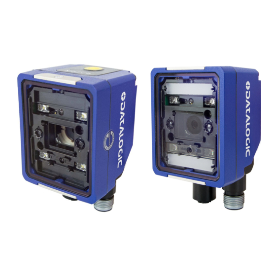
Page 13: General View
General View Standard Model PoE Model General View of DPM Models Reading Window Accessory Window Cover Mounting Holes (2) X-PRESS Interface Power On LED Ethernet Connector ... - Page 14 Accessory Window Cover Mounting Holes (2) X-PRESS Interface Power On LED Ethernet Connector Ethernet Connection LED Power, COM, I/O Connector 90° Rotating Connector Block Power Over Ethernet Connector COM, Trigger Connector Matrix 220...
- Page 15 General View DPM Models Standard Models Reading Window Details Lens Non Polarized Illuminator LED Aiming System Polarized Illuminator Red Spot (No Read) Diffused Illuminators ...
- Page 16 General View X-PRESS Interface Details Normal Operation X-PRESS Configuration Ready Learn Good Setup Trigger Test Status Push-button Matrix 220...
-
Page 17: Rapid Configuration
CAB-DSxx-S Matrix 220 Alone PG6000 Ethernet Interface Auxiliary Serial Interface (RS232 - Data Monitor) External Trigger (for One Shot or Phase Mode) Figure 1 - Matrix 220 in Stand Alone Layout Product Reference Guide... -
Page 18: Cbx100/Cbx500 Pinout For Matrix 220
Rapid Configuration CBX100/CBX500 Pinout for Matrix 220 The table below gives the pinout of the CBX100/CBX500 terminal block connectors. Use this pinout when the Matrix 220 reader is connected by means of the CBX100/CBX500: Group Label Description Input Power Power Supply Input Voltage +... -
Page 19: Step 2 - Mount And Position The Reader
0.8 Vdc. CAUTION Step 2 - Mount and Position the Reader 1. To mount the Matrix 220, use the mounting brackets to obtain the most suitable position for the reader. The most common mounting configuration is shown in the figure below. - Page 20 Rapid Configuration of the Matrix 220 reader can be made either through the X- PRESS interface (steps 3-4) which requires no PC connection, or by using the DL.CODE Configuration Program (steps 5-6). Select the procedure according to your needs.
-
Page 21: Step 3 - Aim And Autofocus The Reader
If the Autofocus cannot be reached after a timeout of about 3 (three) min- utes Matrix 220 will exit without saving the parameters to memory, the Aim LED will stop blinking and in this case Matrix 220 emits a long low pitched beep. -
Page 22: Step 4 - X-Press Configuration
If the calibration cannot be reached after a timeout of about 5 (five) seconds Matrix 220 will exit without saving the parameters to memory, the Setup LED will stop blinking and in this case Matrix 220 emits a long low pitched beep. -
Page 23: Reset Reader To Factory Default Environment (Optional)
If the autolearning cannot be reached after a timeout of about 3 (three) minutes Matrix 220 will exit without saving the parameters to memory, the Learn LED will stop blinking and in this case Matrix 220 emits a long low pitched beep. -
Page 24: Step 5 - Installing Dl.code Configuration Program
NOTE 2. When the installation is complete the DL.CODE entry is created in the Start>Programs bar under “Datalogic” as well as a desktop icon. Double- click the desktop icon to run it. This configuration procedure assumes a laptop computer, running DL.CODE, is connected to a factory default reader through the Ethernet port. - Page 25 Step 5 - Installing DL.CODE Configuration Program Figure 5 - Device Discovery The discovery feature will also show devices not belonging to the LAN and display them in grey (see Figure 5 3. First the device must be added to the LAN by aligning its IP Address to the network.
- Page 26 LAN and can be configured. The new IP address will also be displayed. 7. Double-click on or drag the device icon into the Selected Device Informa- tion Area. Details about the device will be displayed in this area. Matrix 220...
-
Page 27: Step 6 - Device Configuration
Step 6 - Device Configuration Figure 7 - DL.CODE Opening Window Step 6 - Device Configuration Automatic or Advanced Setup Automatic Setup provides an automatic procedure for setting: optical/ illumination, reading distance, and code definition parameters to obtain the most stable decoding conditions for a single code symbology based on the images presented to the reader. -
Page 28: Automatic Setup
2. The Open Device Configuration window opens showing the list of currently saved configurations (jobs) saved on the device. For new devices, the only saved job is the Default configuration. Click OK. The device enters run mode and begins acquiring images. Matrix 220... - Page 29 Step 6 - Device Configuration 3. Place the application code in front of the reader at the correct application reading distance. 4. Click on the Pause button to stop image acquisition. If the image display area is too dark to see the images being captured, you can drag the Gain and Exposure Time sliders (circled in red in the figure above) to the right to increase visibility.
- Page 30 Polarized or Non Polarized Illuminators. 7. Click Start to begin the procedure. The reader begins acquiring images. At the end of the procedure the Status: Completed message appears. You can Close the Automatic Setup window. Matrix 220...
-
Page 31: Advanced Setup
Step 6 - Device Configuration Your reader is now optimized for decoding. Continue with the Reading Phase configuration described on page 23. Advanced Setup To begin configuration, the reader must be correctly mounted at the correct reading distance for your application so that its Field of View covers the application reading area. - Page 32 4. Place the Grade A Barcode Test Chart in the reading area. Once positioned, stop image acquisition by clicking on the Pause button. 5. Click the Image Settings branch and then click the Image Auto Setup button to automatically acquire the best exposure time and gain values. Matrix 220...
- Page 33 Step 6 - Device Configuration 6. Select the Static or Dynamic Self-Tuning option; Start Autolearn and Apply to the Image Settings. Product Reference Guide...
- Page 34 For applications having multiple lighting or code reading conditions, up to 10 different Image Settings can be configured by adding them with the icon. NOTE 7. Now select the General Image Settings branch and click on the Focus Autolearn button. Matrix 220...
- Page 35 Step 6 - Device Configuration The Reading Distance value is not significant until the Focus Autolearn procedure ends successfully. 8. The Calibrate dialog box opens allowing you to start the procedure. Click Start. Product Reference Guide...
- Page 36 At the end of the calibration you can see the new Reading Distance and Image Density (PPI) values as well as the FOV dimensions. Click Apply. To enlarge the visual image of the code view, you can click on the zoom image icon repositioning it on the code. NOTE Matrix 220...
- Page 37 Step 6 - Device Configuration At this point it is probably a good idea to save the configuration from temporary memory to permanent memory giving it a specific name. NOTE 9. Now place an application specific code in front of the reader and repeat only the Image Auto-Setup to register any changes in lighting or code sur- face contrast.
- Page 38 (enabled by default). If this symbology is among those in your appli- cation it will be shown in the image display with its code symbology name and a small green box around it indicating it is decoded. Matrix 220...
-
Page 39: Reading Phase
Step 6 - Device Configuration The large green box for each symbol indicates the code localization area which by default is equal to the maximum FoV. It can be resized and moved by dragging its borders with the mouse. The code must be found within this area in order to be decoded. -
Page 40: Good Read Setup
XOR. To do this, drag the code icon(s) from their relative Expected Code box into the Expected Code box of the XOR combination you wish to create. Then delete the empty box by selecting it with the mouse (high- lighted) and pressing the delete key on your keyboard. Matrix 220... -
Page 41: Data Formatting
Step 6 - Device Configuration To create a logical AND condition from a logical XOR, create a new Expected Code box using the Add icon. Then drag the desired code icon from one box to the other. Data Formatting 1. Configure your application specific Data Formatting Message(s) from the Configuration Parameters tree area: Message 1, Message 2, etc. -
Page 42: Output Setup
1. Configure your application specific Digital Output(s) and Green/Red Spots (if used) from the Configuration Parameters tree area: Output 1, Output 2, etc. Save the configuration from temporary memory to permanent memory, overwriting the previously saved configuration. NOTE Matrix 220... -
Page 43: Step 7 - Test Mode
Step 7 - Test Mode Step 7 - Test Mode Use a code suitable to your application to test the reading performance of the system. Test 1. Enter the function by pressing and holding the X-PRESS push button until the Test LED is on. Test 2. -
Page 44: Advanced Reader Configuration
For further details on advanced product configuration, refer to the DL.CODE User’s Guide available in the DL.CODE Help menu. Host Mode Programming The reader can also be partially configured from a host computer using the Host Mode programming procedure. Matrix 220... -
Page 45: Introduction
Chapter 2 Introduction Product Description The Matrix 220 imager is the most compact image based barcode reader for top performance with the highest flexibility. The ideal imager reader for Electronics, Automotive, Packaging and Document Handling applications. The Matrix 220 is designed for superior performance thanks to a 1.2 MPixel high resolution sensor, a new platform and stronger decoding libraries. -
Page 46: Standard Application Program
Introduction Matrix 220 has been developed for use in numerous industries like: Automotive • DPM (Direct Part Marked) code validation after marking • Work-in-progress control • Assembly traceability Electronics • Track and trace PCB board manufacturing • Electronic components •... -
Page 47: Excellent Performance
Product Description Excellent Performance • 1.2 MPixels (960x1280) • Electronic Adjustable Focus through software control • Powerful Internal Lighting Systems • Outstanding decoding capability on 1D, 2D, Stacked, Postal symbologies • Excellent performance on DPM applications • Omni-directional reading • Frame Rate up to 45 frames/sec •... -
Page 48: Industrial Strength
In normal operating mode the colors and meaning of the five LEDs are illustrated in the following table: red LED indicates a NO READ result (Figure 8 -, 3) STATUS yellow LED indicates active communication on the main serial port * (Figure 8 -, 4) Matrix 220... - Page 49 Indicator and Keypad Button yellow LED indicates the status of the reading phase TRIGGER (Figure 8 -, 5) green LED confirms successful reading (Figure 8 -, 6) GOOD green LED indicates that the reader is ready to READY operate (Figure 8 -, 7) * When connected to a Fieldbus network through the CBX500, the COM LED is always active, even in the absence of data transmission, because of polling...
-
Page 50: Aiming System
When associated with the No Read event, the red spot illuminates the target area to indicate that decoding has not occurred correctly according to the configuration requirements.(i.e. no code has been read). Green Spot Red Spot Figure 10 - Matrix 220 Good Read/No Read LED Spots Matrix 220... -
Page 51: Id-Net
ID-NET ID-NET The ID-NET network is a built-in high-speed interface dedicated for high-speed reader interconnection. ID-NET is in addition to the Main and Auxiliary serial interfaces. The following network configurations are available: • ID-NET Synchronized: Single station – multiple readers ID-NET interface allows local connection of multiple readers reading different sides of the same target. -
Page 52: X-Press Human Machine Interface
Test with bar graph visualization to check static reading performance • Aim/Autofocus to turn on the LED pointers to aid positioning and focusing • Setup to perform Exposure Time and Gain calibration • Learn to self-detect and auto-configure for reading unknown codes Matrix 220... -
Page 53: X-Press Functions
X-PRESS Human Machine Interface X-PRESS Functions Quick access to the following functions is provided by an easy procedure using the push button: 1. Press the button (the Status LED will give a visual feedback). 2. Hold the button until the specific function LED is on (Test, Aim, Setup or Learn). -
Page 54: Focus/Aim
If the calibration cannot be reached after a timeout of about 5 (five) seconds Matrix 220 will exit without saving the parameters to memory, the Setup LED will stop blinking and in this case Matrix 220 emits a long low pitched beep. -
Page 55: Diagnostic Indication
Blink Model Description Matrix 220 readers are described by their model number which indicates the characteristics listed in the diagram below. Not all combinations are available. For a complete list of combinations see the Models tab on the Product page of the website. -
Page 56: Internal Lighting Systems
Introduction Internal Lighting Systems There are two different models of Internal Lighting Systems for Matrix 220 readers. The Standard Internal Lighting System is made up of 4 white light LEDs. The DPM Internal Lighting System has a combination of three different types of Illuminators which can be selected individually depending on the Direct Part Mark application requirements. - Page 57 Accessories Accessory Description Order No. CBL-1496 Term. Resist. Thin M12/5P/Female 93A050047 Connectivity CBX100 Compact Connection Box 93A301067 CBX500 Modular Connection Box 93A301068 BM100 Backup Module for CBX100/500 93ACC1808 BM150 Display Module for CBX500 93ACC1809 Various Fieldbus Host Interface Modules and All-In-One Connection Box Kits are available BA100 DIN Rail Adapters 93ACC1821...
-
Page 58: Application Examples
Figure 13 - Unidose Flow-Pack with PDF417 Code Figure 14 - Overprinted Barcode Readable by Matrix 220 also Through the Envelope Window Film Figure 15 - Barcode Printed on Curved Surface Readable by Matrix 300N in spite of Image... -
Page 59: Direct Part Marking
Application Examples Direct Part Marking Matrix 220 is also very powerful in reading low-contrast direct part marked codes. Figure 16 - Dot Matrix Code Directly Marked on Metal Surface by Using Dot Peening Technol- Figure 17 - Dot Peening Marking on Metal Surface with Multi-dot per Code Element... -
Page 60: Laser Marking/Etching Technology
Figure 20 - Data Matrix Code Directly Marked on PCB Surface by Using Laser Etching Technol- If application codes must be read which are produced by Laser Marking in real time, use Matrix 220 models incorporating YAG Filters in order to avoid burning the CMOS sensor. -
Page 61: Installation
Chapter 3 Installation Package Contents Verify that the Matrix 220 reader and all the parts supplied with the equipment are present and intact when opening the packaging; the list of parts includes: • Matrix 220 reader (w/connector plug/cover) • Quick Reference Guide •... -
Page 62: Mechanical Dimensions
Installation Mechanical Dimensions Matrix 220 can be installed to operate in different positions. The two screw holes (M3 x 4mm depth) on the body of the reader are for mechanical fixture. The diagrams below give the overall dimensions of the reader and may be used for its installation. - Page 63 Mechanical Dimensions 37.6 [1.48] [2.30] [1.85] optical axis Ø3 n°2 optical axis [Ø0.12] 4 mm 20.5 [0.81] [inch] Figure 23 - Overall Dimensions Standard Models; Connector at 90° Product Reference Guide...
- Page 64 Installation 20.5 [0.81] 37.6 [1.48] [1.85] [1.68] optical axis Ø3 n°2 [Ø0.12] 4 mm optical axis [inch] Figure 24 - Overall Dimensions with Accessory Cover (ESD or YAG); Connector at 0° Matrix 220...
- Page 65 Mechanical Dimensions [2.48] 37.6 [1.85] [1.48] optical axis Ø3 n°2 4 mm [Ø0.12] optical axis 20.5 [0.81] [inch] Figure 25 - Overall Dimensions with Accessory Cover (ESD or YAG); Connector at 90° Product Reference Guide...
- Page 66 Installation 20° [inch] Figure 26 - Mounting Bracket Overall Dimensions Matrix 220...
-
Page 67: Mounting And Positioning Matrix 220
Mounting And Positioning Matrix 220 Mounting And Positioning Matrix 220 Using the Matrix 220 mounting brackets you can obtain rotation on the various axes of the reader as shown in the diagram below: Figure 27 - Positioning with Mounting Bracket... - Page 68 Installation Matrix 220 is able to decode code labels at a variety of angles; however significant angular distortion may degrade reading performance. When mounting Matrix 220, take into consideration these ideal label position angles: Pitch or Skew 10° to 20° and Tilt 0°.
- Page 69 Mounting And Positioning Matrix 220 Figure 29 - Tilt Angle Considerations Chapter 6 for FOV vs. Reading Distance considerations. Product Reference Guide...
-
Page 70: Mounting Accessory Covers
2. Make sure the window is clean of any dirt, dust or fingerprints. If necessary wipe it with a clean tissue. 3. Place the cover over the Matrix 220 reader and press down on the cover frame edges until the screw holes align. -
Page 71: Electrical Connections
These accessory cables terminate in an M12 17-pin connector on the Matrix 220 side and in a 25-pin male D-sub connector on the CBX side. All Matrix 220 Power over Ethernet (PoE) models have an additional COM and Trigger connector which can be connected through custom cables. See Appendix A for direct wiring details. - Page 72 * Do not leave floating, see " for connection details. To avoid electromagnetic interference when the reader is connected to a CBX connec- tion box, verify the jumper positions in the CBX as indicated in its Installation Manual. NOTE Matrix 220...
-
Page 73: Power Supply
Power Supply Power Supply Power requirements and conditions depend on the Matrix 220 model: Standard or PoE (Power over Ethernet). Standard Models For these models power can be supplied to the reader through the CBX100/500 spring clamp terminal pins as shown in... -
Page 74: Main Serial Interface
Receive Data SGND Signal Ground It is always advisable to use shielded cables. The overall maximum cable length must be less than 15 m (49.2 ft). User Interface SGND SGND Reader Figure 33 - RS232 Main Interface Connections Matrix 220... -
Page 75: Rs422 Full Duplex Interface
Main Serial Interface RS422 Full Duplex Interface The RS422 full-duplex (5 wires + shield) interface is used for non-polled communication protocols in point-to-point connections over longer distances (max 1200 m / 3940 ft) than those acceptable for RS232 communications or in electrically noisy environments. -
Page 76: Id-Net Interface
Reader's chassis may be connected to earth. • Network inside the same building. Baudrate Table Baudrate 125 kbps 250 kbps 500 kbps 1 Mbps Cable Length 1200 m 900 m 700 m * Application dependent, contact your Datalogic representative for details. Matrix 220... -
Page 77: Id-Net Response Time
ID-NET Interface The default ID-NET baudrate is 500 kbps. Lower ID-NET baudrates allow longer cable lengths. NOTE ID-NET Response Time The following figure shows the response time of the ID-NET network. This time is defined as the period between the Trigger activation and the beginning of data transmission to the Host. -
Page 78: Id-Net Network Termination
The network must be properly terminated in the first and last reader of the network. This is done by setting the ID-NET Termination Resistance Switch in the CBX100/500 to ON. ID-NET Connection Diagrams Figure 37 - ID-NET Network Connections with isolated power blocks Matrix 220... - Page 79 ID-NET Interface Figure 38 - ID-NET Network Connections with Common Power Branch Network Product Reference Guide...
- Page 80 Electrical Connections Figure 39 - ID-NET Network Connections with Common Power Star Network Matrix 220...
-
Page 81: Auxiliary Rs232 Interface
Auxiliary RS232 Interface Auxiliary RS232 Interface The RS232 auxiliary interface is available for Point-to-Point connections. When it is connected to the host computer it allows transmission of code data. The parameters relative to the aux interface (baud rate, data bits, etc.) can be defined through the Reading Phase step (Channels) in DL.CODE. -
Page 82: Inputs
Power Source - External Trigger External Trigger A (polarity insensitive) External Trigger B (polarity insensitive) Power Reference - External Trigger The yellow Trigger LED (Figure 8 -, 5) is on when the active state of the External Trigger corresponds to ON. Matrix 220... -
Page 83: External Trigger Input Connections Using Matrix 220 Power
Power from the Vdc/GND spring clamps is available directly to the Input Device on the +V/-V spring clamps, and does not pass through the Power Switch (ON/OFF) inside the CBX. Disconnect the power supply when working inside the CBX. CAUTION Figure 41 - PNP External Trigger Using Matrix 220 Power Product Reference Guide... - Page 84 Electrical Connections Figure 42 - NPN External Trigger Using Matrix 220 Power Matrix 220...
-
Page 85: External Trigger Input Connections Using External Power
Input 2 B (polarity insensitive) Power Reference - External Trigger Input 2 Connections Using Matrix 220 Power Power from the Vdc/GND spring clamps is available directly to the Input Device on the +V/-V spring clamps, and does not pass through the Power Switch (ON/OFF) inside the CBX. -
Page 86: Input 2 Connections Using External Power
Electrical Connections Input Device Power to Input Device Input Input Device Signal Reference Figure 45 - PNP Input 2 Using Matrix 220 Power Input Device Power to Input Input Device Signal Input Device Reference Figure 46 - NPN Input 2 Using Matrix 220 Power... -
Page 87: Input 3 Connections (Cbx500 Only)
Outputs Input 3 Connections (CBX500 Only) RESERVED Figure 49 - Input 3 Using External Power Do not connect to I3A or I34B signals, they are reserved. CAUTION Outputs When Outputs 1 and 2 are connected through the CBX connection box, they become opto-isolated and polarity sensitive and acquire the electrical characteristics listed below. -
Page 88: Output 1 And 2 Connections Using Matrix 220 Power
CBX. Disconnect the power supply when working inside the CBX. CAUTION Output 1 Device Output 2 Device Power to Output Power to Output Signal Output Device Signal Output Device Output Output Device Device Reference Reference Figure 50 - PNP/Open Emitter Output Using Matrix 220 Power Matrix 220... - Page 89 Reference Output Device Output Reference Signal Output Signal Figure 51 - NPN/Open Collector Output Using Matrix 220 Power Output 1 and 2 Connections Using External Power Output 1 Device Output 2 Device Pulled up to External Pulled up to External...
-
Page 90: Output 3 Connections Using Matrix 220 Power (Cbx500 Only)
Electrical Connections Output 3 Connections Using Matrix 220 Power (CBX500 Only) Output 3 Device Power to Output Device Output Output Device Signal Reference Figure 54 - Output 3 Using Matrix 220 Power Output 3 Connections Using External Power (CBX500 Only) -
Page 91: On-Board Ethernet Interface
PC. There is no need to use a crossover adapter since Matrix 220 incorporates an auto-cross function. A CAB-ETH-M0x cable can be used to connect to a LAN. On the Matrix 220 on-board Ethernet interface the following communication channels are available: •... -
Page 92: Typical Layouts
NOTE The Master/Slave Role is only significant for the Internal ID-NET Network. If your lay- out doesn’t use the ID-NET network then the device’s Role is not significant and can be ignored. NOTE Matrix 220... -
Page 93: Ethernet Connection
The Ethernet connection is possible in two different layouts. In a Point-to-Point layout the reader is connected to a local host by using a CAB- ETH-M0x cable. There is no need to use a crossover adapter since Matrix 220 incorporates an autocross function. - Page 94 Typical Layouts When using a Local Area Network (LAN), one or more Matrix 220 readers can be connected to the network by using CAB-ETH-M0x cables: Alone Alone Alone Matrix 220 Power Host Switch Ethernet Interface ...
-
Page 95: Serial Connection
When One Shot or Phase Mode operating mode is used, the reader can be acti- vated by an External Trigger (for example a pulse from a photoelectric sensor) when the object enters its reading zone. PG6000 Host CAB-DSxx-S Matrix 220 Alone Main Serial Interface (RS232 or RS422 Full-Duplex) ... -
Page 96: Fieldbus Connection
When One Shot or Phase Mode operating mode is used, the reader can be acti- vated by an External Trigger (photoelectric sensor) when the object enters its reading zone. Power CAB-DSxx-S CBX500 Matrix 220 Alone Fieldbus Interface (Profibus, DeviceNet, etc.) ... -
Page 97: Pass-Through
Pass-Through Pass-Through The pass-through layout allows each device working Alone, to collect data from one or more pass-through input channels and send this data plus its own on one or more different output channels. In this way independent devices can be connected together in combinations to create multi device networks. -
Page 98: Id-Net Multidata Network (Pass-Through)
(i.e. right reader above). The ID-NET Master always has at least one pass-through configuration to collect the ID-NET Slaves data and send it to the Host. Slave devices cannot receive data from a pass-through ID-NET input channel and Master devices cannot send data on an ID-NET output channel. NOTE Matrix 220... -
Page 99: Id-Net Synchronized Network
ID-NET Synchronized Network All devices always support multiple output channels (i.e. for data monitoring). In a Pass-through layout each device can have a different operating mode: Con- tinuous, One Shot, Phase Mode, etc. ID-NET Synchronized Network When the device is working Synchronized, the ID-NET connection is used to col- lect data from several readers to build a multi-point or a multi-sided reading system;... - Page 100 CAB-AUX03 Figure 64 - ID-NET Synchronized Layout Figure 65 - Matrix 220 Master with CBX500 + Matrix 220 Slaves with QL100 If the Backup and Restore function is not required, then a QL300 can be used to connect the master reader.
- Page 101 ID-NET Synchronized Network The same configuration can be made to a Host using the on-board Ethernet interface to the Master. The TCP/IP Ethernet and ID-NET interfaces are con- nected as shown in the figure below. Power ID-NET ID-NET Synchronized Synchronized Slave#1 Slave#n...
-
Page 102: Reading Features
= horizontal, vertical or diagonal viewing angles. α d = reading distance (in mm) from window surface to code surface = offset (in mm) from center of lens to external window surface Figure 70 - Reading Distance References Matrix 220... -
Page 103: Global Fov Diagrams
Global FOV Diagrams Example: The FOV for a Matrix 220 355-0x0 at a reading distance of 200 mm is: = 2 [(200 mm + 4 mm) * tan (24°/2)] ≅ 87 mm = 2 [(200 mm + 4 mm) * tan (18°/2)] ≅ 65 mm Global FOV Diagrams The following diagrams are given for typical performance at 25°C using high quality... -
Page 104: Mm Models (38°Horizontal View Angle)
Reading Features 7 mm Models (38°Horizontal View Angle) Code 128 Reading Distance Figure 71 - 7 mm Global FOV Diagram 2D Data Matrix ECC 200 Reading Distance Figure 72 - 7 mm Global FOV Diagram Matrix 220... -
Page 105: Mm Models (24° Horizontal View Angle)
Global FOV Diagrams 12 mm Models (24° Horizontal View Angle) 1D Code 128 Reading Distance Figure 73 - 12 mm Global FOV Diagram 2D Data Matrix ECC 200 Reading Distance Figure 74 - 12 mm Global FOV Diagram Product Reference Guide... -
Page 106: Reading Diagrams
Code Contrast=Standard; Decoding For reading 2D code symbologies: Complexity=Medium • When defining a HW/SW configuration for the Matrix 220 for conditions dif- ferent from those of the reference diagrams, it is suggested to keep in mind the following rules: Exposure Time •Changes in... -
Page 107: Matrix 220 (7 Mm Models) 1D Codes
Reading Diagrams Matrix 220 (7 mm models) 1D Codes Matrix 220 (7 mm lens - 38° Horizontal View Angle) Code 128 0.20 mm (8 mils) 11 12 inch Reading Distance Conditions Hardware Settings Code Symbology Code 128 Code Resolution 8 mils Tilt Angle 0°... - Page 108 Reading Features Matrix 220 (7 mm lens - 38° Horizontal View Angle) Code 128 0.30 mm (12 mils) inch Reading Distance Conditions Hardware Settings Code Symbology Code 128 Code Resolution 12 mils Tilt Angle 0° Skew Angle 15° Focusing Distance...
-
Page 109: Matrix 220 (7 Mm Models) 2D Codes
Reading Diagrams Matrix 220 (7 mm models) 2D Codes Matrix 220 (7 mm lens - 38° Horizontal View Angle) Data Matrix 0.13 mm (5 mils) -0.5 -1.0 -1.5 -2.0 2.0 2.5 3.5 4.0 inch Reading Distance Conditions Hardware Settings Code Symbology... -
Page 110: Matrix 220 (12 Mm Models) 1D Codes
Reading Features Matrix 220 (12 mm models) 1D Codes Matrix 220 (12 mm lens - 24° Horizontal View Angle) Code 128 0.25 mm (6 mils) inch Reading Distance Conditions Hardware Settings Code Symbology Code 128 Code Resolution 6 mils Tilt Angle 0°... - Page 111 Reading Diagrams Matrix 220 (12 mm lens - 24° Horizontal View Angle) Code 128 0.33 mm (10 mils) 16 17 18 19 20 23 24 25 inch Reading Distance Conditions Hardware Settings Code Symbology Code 128 Code Resolution 10 mils Tilt Angle 0°...
-
Page 112: Matrix 220 (12 Mm Models) 2D Codes
Reading Features Matrix 220 (12 mm models) 2D Codes Matrix 220 (12 mm lens - 24° Horizontal View Angle) Data Matrix 0.076 mm (3 mils) 1.00 0.75 0.50 0.25 -0.25 -0.50 -0.75 -1.00 3.00 3.25 3.50 3.75 4.00 4.25 inch... -
Page 113: Maximum Line Speed And Exposure Time Calculations
It may also depend on code printing quality, and reader position. Example: A Matrix 220 using: Internal Lighting Mode = Very High Power Strobe Exposure Time (μs) = 100 μs Code Resolution (X) = 0.254 mm (10 mils) has a maximum line speed of: 0.254 (mm) / 0.0001 (s) = 2540 mm/s... - Page 114 Different Power Strobed lighting levels can be set. To avoid LED array overheating, for Power Strobed settings, the program automati- cally limits the range of allowed values for the Exposure Time parameter. Therefore, after changes to Internal Lighting, recheck Exposure Time. NOTE Matrix 220...
-
Page 115: Software Configuration
Chapter 7 Software Configuration Software configuration of your Matrix 220 for static reading or simple code reading applications can be accomplished by the Rapid Configuration procedure using the X-PRESS HMI (which requires no external configuration program). This procedure is described in Chapter 1, Steps 3-4. -
Page 116: Reader Configuration
Select the Static or Dynamic Self-Tuning option; Start Image Auto-Setup and Apply to the Image Settings. The Advanced Setup window works interactively so that you can see the results of the parameter setting changes as well as the decoding results (Results panel). Matrix 220... - Page 117 Reader Configuration Figure 75 - Decoding Results OK Product Reference Guide...
-
Page 118: Manual Calibration
Longer exposure times can be set if the power strobe level is low- ered. NOTE High gain settings may produce a grainy image that may affect the decoding process. Figure 76 - Example Under Exposure: Too Dark Matrix 220... -
Page 119: Over-Exposure
Reader Configuration Over-exposure To correct this result it is recommended to change the following parameters in their order of appearance: 1. decrease the Gain 2. decrease the Exposure Time Figure 77 - Example Over Exposure: Too Light Product Reference Guide... -
Page 120: Moving Code Out Of The Field Of View
• reposition the reader • use the Delay on Trigger and set the Time or Space values. Figure 78 - Example Out of FOV Figure 79 - Add Delay on Trigger to Correct Out of FOV Matrix 220... -
Page 121: Multi Image Acquisition Settings
Multi Image Acquisition Settings Multi Image Acquisition Settings Image When controlled variable conditions occur in the application, Multiple Acquisition Settings can be defined to create a database of parameter groups that handle each specific application condition. This database of pre-defined settings improves system flexibility and readiness by being applied either automatically or selectively by an activation event. -
Page 122: Automatic Image Settings Selection
Good Read. For this group of items the last Image Setting used will be correct for the next item and so we start each cycle with the acquisition that will potentially produce a Good Read. Matrix 220... -
Page 123: External Image Settings Selection
Multi Image Acquisition Settings External Image Settings Selection There are some applications where the lighting conditions are known before each item is read and therefore we can pre-select the correct Image Setting from an external source. When the Image Settings Selection is External, Acquisition Sequences are created and by default each Image Setting has its own Acquisition Sequence. - Page 124 In this case the Start Acquisition From parameter can improve the read rate for that Sequence. It has no meaning for a Sequence containing only one Image Setting. Matrix 220...
-
Page 125: Image Cropping
Advanced Setup tab by clicking on the Add Cropping Region icon as shown below. In Matrix 220 the frame rate is dependent on the number of rows and columns in the defined window. Image cropping allows reducing the Image processing area from the full FoV to a smaller area where codes are present. - Page 126 Software Configuration By dragging the edges with the mouse (resizing) you can crop the image to a specific location where codes are present. The numbers in the blue boxes refer to pixel references. Matrix 220...
- Page 127 Image Cropping The cropped area can be moved by dragging the center. You can also set the cropped image size and position through the Cropping Region Area group of parameters; size = Width and Height, position = Left, Top (x,y) coordinates. Product Reference Guide...
-
Page 128: Direct Part Marking Applications
For QR code the parameter allows the Dot Peen Decoding algorithm to be selected which improves the decode rate for low quality Direct Part Mark codes and in general for Direct Part Mark codes with dot peening type module shapes. Matrix 220... -
Page 129: Matrix 220 Recommended Illumination For Dpm
Direct Part Marking Applications Matrix 220 Recommended Illumination for DPM In the following table these macro-cases are listed, and for each of them, the most suitable Matrix 220 lighting systems used to resolve the application. External Application Characteristics White Polarized... -
Page 130: Illumination Examples For Dpm Applications
Software Configuration Illumination Examples for DPM Applications The following images have been captured by a Matrix 220 DPM model reader to demonstrate positioning and contrast considerations for DPM applications. Code Positioning with Respect to Illumination Since the various internal illuminators on the DPM models are located above or below the sensor, the light emitted from them can cause glare in the respective area of the image. -
Page 131: Code Contrast
Direct Part Marking Applications Code Contrast In the images below, the contrast of the code with respect to the surface material is sufficient to overcome the glare of the Non Polarized and Diffused illuminators. However, for the Polarized illuminator the contrast is not sufficient no matter what the position in the FoV. -
Page 132: Image Filter
. See the DL.CODE User’s Manual for examples of Image Filter application. Erode Filter enlarges the image dark zones to increase readability. Before - No Read After - Readable Dilate Filter enlarges the image white zones to increase readability. Before - No Read After - Readable Matrix 220... - Page 133 Direct Part Marking Applications Close filter eliminates dark areas (defects) in the white zones of the image. Before - No Read After - Readable Open filter eliminates white areas (defects) in the dark zones of the image. Before - No Read After - Readable Contrast Stretching filter maximizes image contrast.
- Page 134 After - Readable Histogram Equalization filter makes the gray level distribution uniform. Before - No Read After - Readable Smoothing filter deletes small (insignificant) details in the center of the image. Before - No Read After - Readable Matrix 220...
- Page 135 Direct Part Marking Applications Sharpening filter improves out of focus images. Before - No Read After - Readable Deblurring filter improves blurred images. Before - No Read After - Readable Deblurring filter improves blurred images. Before - No Read After - Readable Product Reference Guide...
-
Page 136: Pass-Through Configurations
Before - No Read After - Readable Pass-Through Configurations DL.CODE and Matrix 220 readers support pass-through multi device configurations. The pass-through configuration allows individually working devices (Alone), to collect data from other devices (also working Alone), and pass this data to a third device through a different communication channel. - Page 137 Pass-Through Configurations Product Reference Guide...
-
Page 138: Internal Network Configurations
The general procedure (also detailed in the following paragraphs) is to: 1. Mount all the readers mechanically (refer to "Mechanical Dimensions" on page 46 "Mounting And Positioning Matrix 220" on page 51) and elec- trically (refer to "ID-NET Interface" on page 60) with factory default settings (Layout Type = Alone, Internal Network Role = Slave). - Page 139 Internal Network Configurations You will be advised that the device role will be changed to Master. Click OK. The Net Autoset feature automatically starts to find Slave devices connected to the ID-NET network of the Master. Product Reference Guide...
- Page 140 Depending on the application, select one of the Default Internal Network Configurations: Multidata, Synchronized Phase Mode or Synchronized PackTrack. This selection will open a pre-configured job for the Master reader according to the selection. Follow the specific application instructions in the following paragraphs. Matrix 220...
-
Page 141: Multidata Id-Net Network Configurations
Internal Network Configurations Multidata ID-NET Network Configurations The Multidata ID-NET network communications between Master and Slave are managed by the application job (configuration) using the pass-through feature. A pre-configured job is loaded with the correct pass-through settings for both the Master and Slaves when the Default Multidata Configuration is selected from the Internal Network Setting feature. - Page 142 (manually) connect them one by one to perform Image Settings. NOTE Open the Slave specific application job, (it will either have the new name saved from the Master or Temp depending on the Save on Slave Device selection). Matrix 220...
- Page 143 Internal Network Configurations When the configuration opens, pause run mode and set all the application specific configuration parameters (including Image Settings). Verify the focus and decoding with the capture image button. Product Reference Guide...
- Page 144 (but with all Slave specific configuration parameters), has been saved to the Slaves. No parameters have been cloned from the Master. There are no common parame- ters managed by the Master for Multidata configurations. Matrix 220...
- Page 145 Internal Network Configurations Product Reference Guide...
-
Page 146: Synchronized Id-Net Network Configurations
If necessary, Slave device photometric (Image Settings) parameters must be config- ured separately through DL.CODE. This is preferably done through each device’s Ethernet TCP/IP channel. If Slave devices are not connected to Ethernet you must temporarily (manually) connect them one by one to perform Image Settings. NOTE Matrix 220... - Page 147 Internal Network Configurations Open the cloned application job. Product Reference Guide...
- Page 148 (Reading Phase step) • Images Saving if used (Data Formatting step) • Encoder Sensor: if used, (for all Slaves, the Encoder Type must be set to Internal) Verify the focus and decoding with the capture image button. Matrix 220...
- Page 149 Internal Network Configurations 3. Now save them, overwriting the cloned application job Figure 83 - Saving Synchronized Phase Mode Configuration to Slave Repeat this procedure for each Slave device until the entire network is configured. "ID-NET Synchronized Network" on page 83 for an example.
-
Page 150: Verify Master/Slave Synchronized Configuration
Mask field in place of each Code Content field to verify if all devices are reading. To do this: 1. Connect to the Master device via Ethernet and from the Data Formatting step, change each Expected Code Field Type from Code Content to Reading Mask. Matrix 220... - Page 151 Internal Network Configurations 2. Run the application and monitor the output data from the DL.CODE Console or a configured channel terminal. The Reading Mask shows which device reads which Expected Code. The mask is composed of a fixed 32-character string (0=No Read or 1=Read) representing the 32 possible readers in an ID-NET network.
- Page 152 To save changed slave parameters here, you must click on the Master and Save the NOTE configuration overwriting it, making sure to select Save on Slave Device but without Clone Master Configuration on Slaves, otherwise all the Slave configuration parame- ters will be overwritten by the Master configuration. Matrix 220...
-
Page 153: Backup And Restore Through Dl.code
Backup and Restore Through DL.CODE Backup and Restore Through DL.CODE DL.CODE allows Backup and Restore to be performed to/from the configuration PC via file or to an external storage device such as BM100. It can be performed for Single Reader and Internal Network (Master/Slave) configurations. -
Page 154: Backup
Backup. If you are performing a backup to a file you will be asked whether to include the firmware or not. At the end of the backup, DL.CODE shows a message indicating successful completion. Matrix 220... -
Page 155: Restore
Backup and Restore Through DL.CODE Restore To perform a Restore: 1. From the DL.CODE Device menu, select either Single Reader Restore (from file on PC); or Restore from external storage device. For ID-NET network Restore, select the Internal Network replacement selection. NOTE If restoring an ID-NET network though the Master, this may take a few minutes. -
Page 156: Replacement
Restore Default Startup Configuration The Default configuration is always present on the reader and in fact it is not modifiable and cannot be deleted. It can always be restored by simply selecting it from the Open from Device configuration list. Matrix 220... -
Page 157: Restore Default Environment
Restore Defaults The same action can be performed from the Device menu >Backup/Restore > Restore Defaults > Restore Default Startup Configuration. The Default Configuration will be set to run at startup and the reader will be reset. Any previously saved configurations on the device will remain in memory, but the Default configuration is set as the startup configuration. -
Page 158: Restore Factory Defaults
Diagnostic Alarms By using the DL.CODE Monitor functions from the File menu (or Monitor icon), you can get information about the state of the ID-NET network. Matrix 220... -
Page 159: Statistics
Statistics Figure 84 - Diagnostic Alarms Statistics Statistics on the reading performance can be viewed by enabling the Statistics panel from the DL.CODE Monitor item selected from the File menu (or Monitor icon). Figure 85 - Reading Statistics Product Reference Guide... -
Page 160: Bm150 Display Module Configuration And Messages
Configuration Through DL.CODE BM150 must be detected through the BM100 backup memory module at power- up/reset and this is done through a command setting in DL.CODE. By connecting the reader to DL.CODE the following parameters can be managed. Matrix 220... -
Page 161: Accessing The Hmi Interface Through Keypad And Display Menu
BM150 Display Module Configuration and Messages In the Device>Settings>Settings>Maintenance window: • Enable BM100 Detection Checked (Enabled): the BM100 backup memory module will be detected on power-up/reset; therefore the BM150 display module (if present), will also be enabled. Unchecked (Disabled): the BM100 backup memory module will not be detected on power-up/reset;... - Page 162 When the reader is connected to DL.CODE, access to the BM150 HMI Interface is dis- abled. NOTE The "Reset Reader to Factory Default Environment" function of the HMI Interface is only available on the local device (reader), and not on the BM150. NOTE Matrix 220...
-
Page 163: Display Messages
BM150 Display Module Configuration and Messages Display Messages The following examples of Remote Display messages are given to help interpret the information reported. The content of these messages depends on the connected reader. Welcome Message: M = scanner model K = software – STD=Standard, SS =Special V = software version R = Device Network Type –... - Page 164 Wrong Rotary Switch Selection Fieldbus Communication Failure Fieldbus Type Mismatch Fieldbus Configuration Error Fieldbus DHCP Problem No XRF Slave(s) Detected Slave Node Alarms (Master only): X = slave node number (1-31) R = Device Network Type – MUL=Multidata, SYN=Synchronized Matrix 220...
- Page 165 BM150 Display Module Configuration and Messages Network State (Master only): M = Master diagnostic condition; S = Slave diagnostic condition: * = scanner OK - =scanner not detected at startup ? =scanner detected at startup but not responding to diagnostic polling ! = scanner diagnostic error Standard Reading Results: A = reading result –...
-
Page 166: Bm150 Backup And Restore Procedure
For Master/Slave networks any other configurations (jobs) stored in the device mem- ory will not be backed up. Therefore upon a restore, all jobs other than the startup configuration will be overwritten (erased). It is strongly recommended to save all con- figurations to backup files. CAUTION Matrix 220... - Page 167 BM150 Display Module Configuration and Messages The Slaves must always be configured with the same network baudrate as the Master for correct functioning including performing Backup and Restore procedures. Backup and Restore functions cannot be interrupted once started. Backup To perform 1.
-
Page 168: Maintenance
See General View. Dust, dirt, etc. on the lens cover may alter the reading performance. Repeat the operation frequently in particularly dirty environments. Use soft material and alcohol to clean the lens cover and avoid any abrasive substances. Matrix 220... -
Page 169: Troubleshooting
When wiring the device, pay careful attention to the signal name (acronym) on the CBX100/500 spring clamp connectors (Chapter 4). If you are con- nectiing directly to the Matrix 220 M12 17-pin connector, pay attention to the pin number of the signals (Appendix •... - Page 170 Data Formatting parameters on the Data Format- no result is transmit- ting step. ted by the reader at the end of the reading phase collection. Image not clear: verify the Focus procedure Image focused but not verify the Calibrate Image Density procedure. decoded: Matrix 220...
- Page 171 Run the Rapid Configuration procedure in Chapter 1. Position the reader as described in "Mounting And Position- ing Matrix 220" on page 51 and through DL.CODE: Tune the Acquisition Delay on Trigger, if the moving code is out of the reader field of view;...
-
Page 172: Technical Features
CBX connection boxes the electrical features for Output 1 and 2 become the following: Opto-isolated; V = 30 Vdc max.; I = 40 mA continuous max.; 130 mA pulsed max.; = 1 Vdc max. @ 10 mA; P = 90 mW Max. @ 50 °C ambient temp. CE saturation Matrix 220... -
Page 173: Optical Features
Optical Features Optical Features Optical Features Image Sensor CMOS sensor with Global Shutter Image Format 1.3” 1.2 M pixels Frame Rate 45 frames/sec. ± 35° Pitch Tilt 0° - 360° LED Safety to EN 62471 Lenses Focal Length 7 mm, 12 mm Internal Illuminators Lighting System Dual LED Pointers... -
Page 174: Physical Features
Physical Features Dimensions H x W x L Std Matrix 220 connectors at 0° 78 x47 x 38 mm (3.1 x 1.9 x 1.5 in) Std Matrix 220 connectors at 90° 58 x 47 x 58 mm (2.3 x 1.9 x 2.3 in) ESD Matrix 220 connectors at 0°... -
Page 175: Alternative Connections
Appendix A Alternative Connections The connector pinouts and notes given in this appendix are for custom cabling applications. Power, Com and I/O Connector for Standard Models Figure 1 - M12 17-pin male Power, COM and I/O Connector Power, Com and I/O Connector Pinout Name Description Power supply input voltage +... -
Page 176: Com And Trigger Connector For Poe Models
Figure 2 - M12 5-pin male COM and Trigger Connector Com and Trigger Connector Pinout Name Description External Trigger A (polarity insensitive) RS232 Main Serial Receive data signal RS232 Main Serial Transmit data signal External Trigger B (polarity insensitive) RS232 Main Serial Reference Matrix 220... -
Page 177: On-Board Ethernet Connector
On-Board Ethernet Connector In order to meet EMC requirements: • connect the reader chassis to the plant earth ground by means of a flat copper braid shorter than 100 mm; • connect your cable shield to the locking ring nut of the connector. On-Board Ethernet Connector Standard Models A Standard M12 8-pin X-Coded female connector is provided for the on-board Ether-... -
Page 178: Power Over Ethernet (Poe) Models
Power can be applied to any of the data pairs according to the IEEE 802.3af standard for Alternative A (Mid and Endspan) or Alternative B. ID-NET Network Termination The network must be properly terminated by a 120 Ohm resistor at the first and last reader of the network. Matrix 220... -
Page 179: Inputs
Inputs Inputs There are two optocoupled polarity insensitive inputs available on the M12 17- pin connector of the reader: Input 1 (External Trigger) and Input 2, a generic input. See "Inputs" on page 66 for more details. The electrical features of both inputs are: | Min. - Page 180 Figure 5 - PNP Output Connection Figure 6 - NPN Output Connection For NPN output connections, the external interface voltage (Vext) must not exceed the Matrix 220 power supply source voltage (Vdc) otherwise correct output functioning cannot be guaranteed. CAUTION...
- Page 181 Outputs Figure 7 - Push-Pull Output Connection For Matrix 220 PoE models, the internal Digital Output circuitry is not powered and supply power is not available to any Input/Output devices (Vdc=0). Only input device signals can be accepted directly on the M12 17-pin connector without power.
-
Page 182: User Interface - Serial Host
25-pin male connector Name Name How To Build A Simple Interface Test Cable: The following wiring diagram shows a simple test cable including power, exter- nal (push-button) trigger and PC RS232 COM port connections. Figure 8 - Test Cable Matrix 220... -
Page 183: Glossary
Glossary (Association for Automatic Identification and Mobility): AIM Global is the interna- tional trade association representing automatic identification and mobility tech- nology solution providers. AIM DPM Quality Guideline Standard applicable to the symbol quality assessment of direct part marking (DPM) performed in using two-dimensional bar code symbols. It defines modifi- cations to the measurement and grading of several symbol quality parameters. - Page 184 Image Processing Any form of information processing for which the input is an image and the out- put is for instance a set of features of the image. Matrix 220...
- Page 185 Glossary Image Resolution The number of rows and columns of pixels in an image. The total number of pix- els of an image sensor. Image Sensor Device converting a visual image to an electric signal. It is usually an array of CCD (Charge Coupled Devices) or CMOS (Complementary Metal Oxide Semicon- ductor) pixel sensors.
- Page 186 A suite of standard network protocols that were originally used in UNIX environ- ments but are now used in many others. The TCP governs sequenced data; the IP governs packet forwarding. TCP/IP is the primary protocol that defines the Inter- net. Matrix 220...
- Page 188 Datalogic S.p.A. and/or its affiliates • Datalogic and the Datalogic logo are registered trademarks of Data- logic S.p.A.