
Related Manuals for Datalogic Gryphon 2D Series


Summary of Contents for Datalogic Gryphon 2D Series
- Page 1 Gryphon™ 2D Family Gryphon I GD/GBT/GM4500 General Purpose Handheld Area Imager Bar Code Reader Product Reference Guide...
- Page 2 Datalogic and the Datalogic logo are registered trademarks of Datalogic S.p.A. in many countries, including the U.S. and the E.U. Gryphon is a trademark of Datalogic S.p.A. and/or its affiliates, registered in the U.S. All other brand and product names may be trademarks of their respective owners.
-
Page 3: Table Of Contents
INTRODUCTION ............................... 1 About this Manual ................................1 Overview ..................................1 Manual Conventions ..............................2 Technical Support ................................2 Datalogic Website Support ............................2 Reseller Technical Support ............................2 Telephone Technical Support ..........................2 About the Scanner ................................3 Using the GD4500 Reader ............................3 Using the WLC4090 Radio Base ............................4 Radio Base LEDs ...............................4... - Page 4 Baud Rate ..................................41 Data Bits ..................................42 Stop Bits ................................... 43 Parity ....................................43 Handshaking Control ..............................44 RS-232/USB-COM INTERFACES 45 Standard Factory Settings ............................. 45 Intercharacter Delay ............................... 46 Beep On ASCII BEL ................................47 Beep On Not on File ................................ 47 ACK NAK Options ................................
- Page 5 Good Read Beep Length ............................113 Enable/Disable Good Read Indicator ......................... 114 ....................................114 Scanning Features ................................ 115 Scan Mode ................................115 Flash On Time ..............................116 Flash Off Time ..............................117 Stand Mode Indication ............................118 Stand Mode Sensitivity ............................120 Stand Mode Illumination Off Time ........................
- Page 6 Interleaved 2 of 5 CIP HR Enable/Disable ......................174 Datalogic 2 of 5 ................................174 Datalogic 2 of 5 Enable/Disable ......................... 174 Datalogic 2 of 5 Check Character Calculation ....................175 Datalogic 2 of 5 Check Character Transmission ....................175 Datalogic 2 of 5 Length Control .......................... 176 Datalogic 2 of 5 Set Length 1 ..........................
- Page 7 Codabar Set Length 1 ............................182 Codabar Set Length 2 ............................183 ABC Codabar .................................. 184 ABC Codabar Enable/Disable ..........................184 ABC Codabar Concatenation Mode ........................184 ABC Codabar Dynamic Concatenation Timeout ....................185 ABC Codabar Force Concatenation ........................185 Code 11 ...................................
- Page 8 2D Maximum Decoding Time ..........................216 2D Structured Append ............................217 2D Normal/Inverse Symbol Control ........................217 SYMBOLOGY SELECTION 218 Aztec Code ..................................218 Aztec Code Enable / Disable ..........................218 Aztec Code Length Control ..........................218 China Sensible Code ..............................221 China Sensible Code Enable / Disable .......................
- Page 9 Global Prefix/Suffix ............................. 286 Global AIM ID ................................ 287 Label ID ................................. 288 Character Conversion ............................292 Scanning Features ................................ 293 Good Read LED Duration ............................. 293 Scan Mode ................................294 Scanning Active Time ............................295 Aiming Duration Time ............................296 Flash On Time ..............................
- Page 10 NOTES viii Gryphon™ I GD/GBT/GM4500...
-
Page 11: Introduction
Programming can alternatively be performed using the Datalogic Aladdin™ Configuration application, which is available from the Datalogic website listed on the back cover of this manual. This multi-platform utility program allows device configuration using a PC. It communicates to the device using a serial or USB cable and can also create configuration bar codes to print. -
Page 12: Manual Conventions
Telephone Technical Support If you do not have internet or email access, you may contact Datalogic technical support at (541) 349-8283 or check the back cover of your manual for more contact information. -
Page 13: About The Scanner
I GD4500 is a powerful omni-directional reader, so the orientation of the symbol is not important. Datalogic's exclusive patented ' G reen Spot' for good-read feedback helps to improve productivity in noisy environments or in situations where silence is required. -
Page 14: Using The Wlc4090 Radio Base
Amber fading = battery level 1 to 50% Red fading = pre-charge The button can be used to force device connection via the Datalogic Aladdin Software tool and for paging the scanner when it is activated. Refer to the Gryphon I GBT/GM4500 Product Reference Guide (PRG) for a more detailed explanation. -
Page 15: Battery Safety
Always charge the battery at 32° – 104°F (0° - 40°C) temperature range. Use only the authorized power supplies, battery pack, chargers, and docks supplied by your Datalogic reseller. The use of any other power supplies can damage the device and void your warranty. - Page 16 Introduction As with other battery types, Lithium-Ion (LI) batteries will lose capacity over time. Capacity deterioration is noticeable after one year of service whether the battery is in use or not. It is difficult to precisely predict the finite life of a LI battery, but cell manufacturers rate them at 500 charge cycles.
-
Page 17: Programming The Reader
RS-232/USB-COM interface. Alad- din is available on the CD-ROM provided with your product, and also from the Datalogic website. Aladdin allows you to program the reader by selecting con- figuration commands through a user-friendly graphical interface running on a PC. - Page 18 Introduction NOTES Gryphon™ I GD/GBT/GM4500...
-
Page 19: Setup
GBT/GM45 and spare bat- tery pack parts must be periodically recharged : for instance by using a WLC4090 cradle powered up with a 12V Datalogic AC/DC adapter (cod. 8-0935) for at least 30 minutes each 3 months. -
Page 20: Connect Host Interface
Setup Connect Host Interface The scanner kit you ordered to match your interface should provide a compati- ble cable for your installation. If this is not so, contact Technical Support. The scanner can communicate using the interfaces illustrated below. For corded versions, connect the reader cable by inserting the cable into the handle as shown in the following Figure. - Page 21 Setting Up the Scanner Figure 4. Connection to the Host WEDGE RS-232 Specific cables are required for connection to different hosts. The connec- tions illustrated in Figure 4 are examples only. Actual connectors may vary from those illustrated, but the steps to connect the scanner remain the same.
-
Page 22: Stand Installation
Setup Stand Installation Hands-Free Stand/Holder An accessory is available which holds the reader (except those with integrated stand) at a convenient angle, allowing hands free scanning of items. It can also be used as a holder. The holder “cup” can be positioned in any of the angles shown in the figure below. -
Page 23: Setting Up The Reader
* that battery packs of the stocked products GBT/GM45 and spare battery pack parts must be periodically recharged: for instance by using a WLC4090 cradle powered up with a 12V Datalogic AC/DC adapter (cod.8-0935) for at least 30 minutes each 3 months. -
Page 24: Positioning The Base Station
Setup Positioning the Base Station The base station/charger may be set up in desk application to hold the reader in three different positions, either a horizontal or standing or vertical position, in order to provide the most comfortable use depending on the needs. Base Station Positions and related clips to be used Figure 6 - Horizontal Position This position is preferred, unless a different specific positioning is required, for... - Page 25 Setting Up the Reader Figure 8 - Vertical Position This position is preferred when lack of room on the desktop recommends the scanner to be left vertical during recharging. 1. Insert the appropriate parts for the desired base station position. 2.
- Page 26 Setup 3. Using your thumbs, push open the plastic tabs on the bottom of the base to free the wing holders. 4. The stand can now be repositioned in either horizontal or standing posi- tion. To improve the robustness (against accidental falls) of the cradle in Presen- tation Position, it is suggested to add the Shock Absorber addendum as illustrated below.
-
Page 27: Reader, Cradle And Leds Description
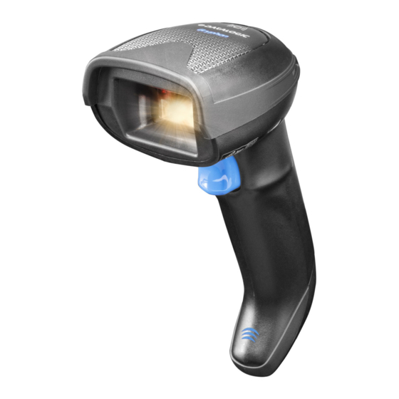
Reader, Cradle and LEDs Description Reader, Cradle and LEDs Description LEDs on the gun provide information about the battery charging status as well as data transmission. Figure 9- Gryphon Base LEDs Scan Window Good Read LED Trigger USB Port Battery & Recharge LED Service Button Cable Release Hole Power LED... -
Page 28: Connecting The Base Station
Setup Connecting the Base Station The following figure shows how to connect the Base Station to a terminal, PC or other host device. Turn off the host before connection and consult the manual for that equipment (if necessary) before proceeding. Connect the interface cable before applying power to the Base Station. -
Page 29: Securing The Dc Power Cord (Optional)
Connecting the Base Station Securing the DC Power Cord (Optional) The DC power cord for the adapter can be secured to the bottom of the base in order to maximize the mechanical retention of the cable itself. The routing of the power cord can be changed to accommodate base station positioning: hor- izontal, stand or wall mount. - Page 30 Setup Host Connection Verify before connection that the reader’s cable type is compatible with your host equipment. Most connections plug directly into the host device as shown in the figure below. Keyboard Wedge interface cables have a ‘Y’ connection where its female end mates with the male end of the cable from the keyboard and the remaining end at the keyboard port on the terminal/PC.
-
Page 31: System And Network Layouts
System and Network Layouts System and Network Layouts Stand Alone Layouts Figure 14 - Single Reader Layout GRYPHON™ HOST CRADLE Figure 15 - Multiple Reader Layout GRYPHON™ HOST CRADLE In stand alone systems, each cradle is connected to a single Host. Product Reference Guide... -
Page 32: Using The Gbt/Gm4500 Scanner
Setup Figure 16 - Multiple Stand Alone Layouts Many stand alone connections can operate in the same physical area without interference, provided all readers and cradles in the system have different addresses. Using the GBT/GM4500 Scanner Scanner LEDs Specific LEDs on the Gryphon Scanner provide information about: good reading result (3GL), battery status and charging status (with micro USB only). -
Page 33: Using The Wlc4090 Radio Base
Amber fading = battery level 1 to 50% Red fading = pre-charge The button can be used to force device connection via the Datalogic Aladdin Software tool and for paging the scanner when it is activated. Refer to the Gryphon I GBT/GM4500 Product Reference Guide (PRG) for a more detailed explanation. -
Page 34: Replacing The Battery Pack
Setup Replacing the Battery Pack Before proceeding, read “Battery Safety” on the preceding pages. Datalogic recommends annual replacement of rechargeable battery packs to ensure maximum performance. NOTE Use the following procedure to change the reader’s battery: 1. With a narrow metallic object (i.e. a coin) or a screwdriver, unscrew the battery cover screw. - Page 35 Replacing the Battery Pack Extract the battery pack from its slot. 3. Insert the new battery in the same position. 4. Replace the battery holder cap, plug in the connector and return the con- tacts circuit to its previous location. When inserting the new battery into the handle, take care to position the battery and the connector as described above.
-
Page 36: Using The Gryphon™ I Gd/Gbt/Gm4500
Setup Using the Gryphon™ I GD/GBT/GM4500 The Gryphon™ I GD4500 normally functions by capturing and decoding codes. The aiming system is activated on trigger pull and indicates the center of the field of view which should be positioned over the bar code: Aiming System Relative Size and Location of Aiming System Pattern 2D Matrix Symbol... - Page 37 Using the Gryphon™ I GD/GBT/GM4500 A red beam illuminates the label. The field of view indicated by the aiming sys- tem will be smaller when the reader is closer to the bar code and larger when it is farther from the code. Symbologies with smaller bars or elements (mil size) should be read closer to the unit.
-
Page 38: Linking The Reader
Setup Linking the Reader Link Datalogic Devices to Base Before configuring the interface it is necessary to link the handheld with the base. To link the handheld and the base simply put it into the base. If the reader was previously linked to another base, you must first scan the Unlink bar code before re-linking to the new base. -
Page 39: Link Scanner As Hid Device To A Bluetooth Host
Power Off Link Scanner as HID device to a Bluetooth host Use this procedure to send data to a Bluetooth host using the Bluetooth HID profile. 1. If using a Bluetooth adapter on the host device, install any driver provided with the adapter. -
Page 40: Interface Selection
• IBM46XX port 9b (a specific cable's required) • Datalogic Magellan Scanners' specific interface Configuring the Interface Scan the programming bar code from the following section which selects the appropriate interface type to match the system the scanner will be connected to. - Page 41 USB Com to simulate RS-232 standard interface Select USB-COM-STD USB-OEM FEATURES $P,HA45,P Set USB-OEM Interface USB-OEM Features (can be used for OPOS/UPOS/JavaPOS) starting on page 87 Select USB-OEM a. Download the correct USB Com driver from www.datalogic.com Product Reference Guide...
- Page 42 (combines USB-KBD emulation and USB-COM) Select USB-Composite OTHER INTERFACES IBM46xx Port 9b Select IBM46xx Port 9b USB HID POS Select USB HID POS USB Toshiba TEC Select USB Toshiba TEC Datalogic Magellan Scanners' specific interface Select Datalogic Magellan Scanners' specific interface Gryphon™ I GD/GBT/GM4500...
- Page 43 Interface Selection KEYBOARD FEATURES $P,HA29,P AT, PS/2 25-286, 30-286, 50, 50Z, 60, 70, 80, 90 & 95 w/Standard Key Encoding Select KBD-AT $P,HA11,P Keyboard Wedge for IBM AT PS2 with standard key encoding but without external keyboard Select KBD-AT-NK $P,HA26,P ...
-
Page 44: Customizing Configuration Settings
Datalogic Aladdin™ is a multi-platform utility program providing a quick and user-friendly configuration method via the RS-232/USB-COM interface. The Aladdin utility is available on the Datalogic website. Aladdin allows you to pro- gram the scanner by selecting configuration commands through a user-friendly graphical interface running on a PC. -
Page 45: Interface Settings
Customizing Configuration Settings Interface Settings The scanner is typically factory-configured with a set of default features standard to the interface type you ordered. See "Interface Selection" on page 30. Global Interface Features, starting on page 39 provides settings configurable by all interface types. - Page 46 Setup NOTES Gryphon™ I GD/GBT/GM4500...
-
Page 47: Configuration Using Bar Codes
Chapter 3 Configuration Using Bar Codes This and following sections provide programming bar codes to configure your scanner by changing the default settings. For details about additional methods of programming, see "Customizing Configuration Settings" on page You must first enable your scanner to read bar codes in order to use this section. - Page 48 Enter/Exit Programming Mode To program features: 1. Scan the ENTER/EXIT PROGRAMMING bar code, available at the top of each programming page, when applicable. 2. Scan the bar code to set the desired programming feature. You may need to cover unused bar codes on the page, and possibly the facing page, to ensure that the scanner reads only the bar code you intend to scan.
-
Page 49: Global Interface Features
Enter/Exit Programming Mode Global Interface Features The following interface features are configurable by all interface types. To set features specific to your interface, turn to that section of this manual. — O OMMANDS GNORE on page 39 USB S USPEND on page 39 Host Commands —... - Page 50 NOTES Gryphon™ I GD/GBT/GM4500...
-
Page 51: Only Interface
RS-232 ONLY Interface Enter/Exit Programming Mode RS-232 ONLY Interface Use the programming bar codes in this chapter if modifications to the standard RS-232 interface settings are necessary to meet your system’s requirements. Additional settings which apply to both the RS-232 and USB interfaces are available in Chapter 5, RS-232/USB-COM Interfaces. -
Page 52: Data Bits
Enter/Exit Programming Mode Data Bits Baud Rate (continued) $CR2BA04 Baud Rate = 19,200 $CR2BA05 Baud Rate = 38,400 $CR2BA06 Baud Rate = 57,600 $CR2BA07 Baud Rate = 115,200 Data Bits This parameter allows the reader to interface with devices requiring a 7-bit or 8-bit ASCII protocol for sending and receiving data. -
Page 53: Stop Bits
RS-232 ONLY Interface Enter/Exit Programming Mode Stop Bits The stop bit(s) at the end of each transmitted character marks the end of trans- mission of one character and prepares the receiving device for the next charac- ter in the serial data stream. The number of stop bits selected (one or two) depends on the number the receiving terminal is programmed to accommo- date. -
Page 54: Handshaking Control
Enter/Exit Programming Mode Handshaking Control Handshaking Control The data interface consists of an RS-232 port designed to operate either with or without the hardware handshaking lines, Request to Send (RTS), and Clear to Send (CTS). Handshaking Control includes the following options: •... -
Page 55: Rs-232/Usb-Com Interfaces
RS-232/USB-COM Interfaces The programming bar codes in this chapter allow modifications to the standard RS-232 and USB-Com interfaces. on page 45 TANDARD ACTORY ETTINGS on page 46 NTERCHARACTER ELAY ASCII BEL on page 47 OT ON on page 47 ACK NAK O PTIONS on page 48 ACK C... -
Page 56: Intercharacter Delay
Enter/Exit Programming Mode Intercharacter Delay Intercharacter Delay This parameter specifies the intercharacter delay between the end of one char- acter and the beginning of the next. The delay can be set within a range of zero (0) to 990 milliseconds in 10ms increments. A setting of zero specifies no delay. -
Page 57: Beep On Ascii Bel
RS-232/USB-COM Interfaces Enter/Exit Programming Mode Beep On ASCII BEL When this parameter is enabled, the scanner issues a beep when a <BEL> char- acter is detected on the RS-232 serial line. <BEL> is issued to gain a user's attention to an illegal entry or other important event. $CR2BB00 ... -
Page 58: Ack Nak Options
Enter/Exit Programming Mode ACK NAK Options ACK NAK Options This enables/disables the ability of the scanner to support the RS-232 ACK/ NAK protocol. When configured, the scanner and/or host sends an “ACK” when it receives data properly, and sends “NAK” when the data is in error. Options are: •... -
Page 59: Ack Character
RS-232/USB-COM Interfaces Enter/Exit Programming Mode ACK Character This setting specifies an ASCII character or hex value to be used as the ACK character. ASCII characters or any hex value from 0 to 0xFF can be selected. See "ACK Character" on page 276 for more detailed programming instructions. Setting to previously defined characters such as XON, XOFF, or host com- mands conflicts with normal operation of these characters. -
Page 60: Ack Nak Timeout Value
Enter/Exit Programming Mode ACK NAK Options ACK NAK Timeout Value This option specifies the amount of time the scanner waits for an ACK character from the host following label transmission. The selectable timeout range is 200 milliseconds to 15,000ms (15 seconds) in 200ms increments. A selection of 0 disables the timeout. -
Page 61: Ack Nak Retry Count
RS-232/USB-COM Interfaces Enter/Exit Programming Mode ACK NAK Retry Count This feature specifies the number of times the scanner retries a label transmis- sion due to a retry condition. The selectable range is from 1 to 254 retries. A selection of 0 disables the count, and a selection of 255 specifies unlimited retries. -
Page 62: Ack Nak Error Handling
Enter/Exit Programming Mode ACK NAK Options ACK NAK Error Handling This feature specifies the method the scanner uses to handle receive errors detected while waiting for an ACK character from the host. Options are: • Ignore errors detected • Process error as valid ACK character •... -
Page 63: Indicate Transmission Failure
RS-232/USB-COM Interfaces Enter/Exit Programming Mode Indicate Transmission Failure This option enables/disables the scanner’s ability to sound an error beep to indicate a transmission failure while in ACK/NAK mode $CR2TF00 Indicate Transmission Failure = Disable Indication $CR2TF01 DEFAULT Indicate Transmission Failure = Enable Indication Disable Character Specifies the value of the RS-232 host command used to disable the scanner. -
Page 64: Enable Character
Enter/Exit Programming Mode Enable Character Enable Character Specifies the value of the RS-232 host command used to enable the scanner. ASCII characters or any hex value from 0 to 0xFF can be selected. See "Enable Character" on page 281 for more detailed programming instructions Setting to previously defined characters such as XON, XOFF, or host commands con- flicts with normal operation of these characters. -
Page 65: Keyboard Interface
Keyboard Interface Use the programming bar codes in this chapter to select options for USB Key- board and Wedge Interfaces. Reference Appendix B, for a listing of standard factory settings. Information about control character emulation which applies to keyboard interfaces is listed in Appendix E, Scancode Tables. -
Page 66: Country Mode
Enter/Exit Programming Mode Country Mode Country Mode This feature specifies the country/language supported by the keyboard. The Country Mode setting is ignored if the interface uses alternate key encod- ing. Setup on PC to use ALT Universal 1. Open Registry Edit 2. -
Page 67: Setting Country Mode
Keyboard Interface Enter/Exit Programming Mode Setting Country Mode $CKBCO00 DEFAULT United States $CKBCO01 French International (Belgian French) $CKBCO02 United Kingdom $CKBCO11 Danish $CKBCO0E French (France) $CKBCO03 German $CKBCO04 Italian Product Reference Guide... - Page 68 Enter/Exit Programming Mode Country Mode Setting Country Mode (continued) $CKBCO0F Norwegian $CKBCO09 Portuguese Portugal $CKBCO0A Spanish $CKBCO0B Swedish $CKBCO13 Swiss French $CKBCO14 Japanese ASCII $CKBCO13 Hungarian Gryphon™ I GD/GBT/GM4500...
- Page 69 Keyboard Interface Enter/Exit Programming Mode Setting Country Mode (continued) $CKBCO0F Czech $CKBCO09 SlovaK $CKBCO0A Romanian $CKBCO0B Croatian $CKBCO13 Polish_214 $CKBCO14 Canadian French Win7 $CKBCO13 Lithuanian Product Reference Guide...
- Page 70 Enter/Exit Programming Mode Country Mode Setting Country Mode (continued) $CKBCO0F Vietnamese $CKBCO09 Russian $CKBCO0A Arabic 101 $CKBCO0B Chinese ASCII $CKBCO13 Thai-Kedmanee $CKBCO14 Albanian $CKBCO13 Arabic 102 Gryphon™ I GD/GBT/GM4500...
- Page 71 Keyboard Interface Enter/Exit Programming Mode Setting Country Mode (continued) $CKBCO0F Arabic 102 AZERTY $CKBCO09 Azeri Cyrillic $CKBCO0A Azeri Latin $CKBCO0B Belarusian $CKBCO13 Bosnian Cyrillic $CKBCO14 Bosnian Latin $CKBCO13 Bulgarian Cyrillic Product Reference Guide...
- Page 72 Enter/Exit Programming Mode Country Mode Setting Country Mode (continued) $CKBCO0F Bulgarian Latin $CKBCO09 Canadian French (Legacy) $CKBCO0A Canadian Multilingual $CKBCO0B Chinese (Simplified) $CKBCO13 Chinese (Traditional) $CKBCO14 Czech Programmers $CKBCO13 Czech QWERTY Gryphon™ I GD/GBT/GM4500...
- Page 73 Keyboard Interface Enter/Exit Programming Mode Setting Country Mode (continued) $CKBCO0F Dutch Netherland $CKBCO09 Estonian $CKBCO0A Faeroese $CKBCO0B Finnish $CKBCO13 French (Canada) 2000/XP $CKBCO14 French (Canada) 95/98 $CKBCO13 Galician Product Reference Guide...
- Page 74 Enter/Exit Programming Mode Country Mode Setting Country Mode (continued) $CKBCO0F Greek $CKBCO09 Greek Latin $CKBCO0A Greek Polytonic $CKBCO0B Greek220 $CKBCO13 Greek220 Latin $CKBCO14 Greek319 $CKBCO13 Greek319 Latin Gryphon™ I GD/GBT/GM4500...
- Page 75 Keyboard Interface Enter/Exit Programming Mode Setting Country Mode (continued) $CKBCO0F Hebrew Israel $CKBCO09 Hungarian_101KEY $CKBCO0A Icelandic $CKBCO0B Irish $CKBCO13 Italian_142 $CKBCO14 Japanese (Shift-JIS) $CKBCO13 Kazakh Product Reference Guide...
- Page 76 Enter/Exit Programming Mode Country Mode Setting Country Mode (continued) $CKBCO0F Korean (Hangul) $CKBCO09 Korean ASCII $CKBCO0A Kyrgyz Cyrillic $CKBCO0B Latin America $CKBCO13 Latvian $CKBCO14 Latvian QWERTY $CKBCO13 Lithuanian_IBM Gryphon™ I GD/GBT/GM4500...
- Page 77 Keyboard Interface Enter/Exit Programming Mode Setting Country Mode (continued) $CKBCO0F Macedonian -FYROM $CKBCO09 Maltese_47KEY $CKBCO0A Mongolian-Cyrillic $CKBCO0B Polish Programmer $CKBCO13 Portuguese Brazil $CKBCO14 Portuguese Brazilian ABNT $CKBCO13 Portuguese Brazilian ABNT2 Product Reference Guide...
- Page 78 Enter/Exit Programming Mode Country Mode Setting Country Mode (continued) $CKBCO0F Romanian Legacy $CKBCO09 Romanian Programmer $CKBCO0A Romanian Standard $CKBCO0B Russian Typewriter $CKBCO13 Serbian Cyrillic $CKBCO14 Serbian Latin $CKBCO13 Slovak QWERTY Gryphon™ I GD/GBT/GM4500...
- Page 79 Keyboard Interface Enter/Exit Programming Mode Setting Country Mode (continued) $CKBCO0F Slovenian $CKBCO09 Spanish Variation $CKBCO0A Swiss German $CKBCO0B Tatar $CKBCO13 Turkish F $CKBCO14 Turkish Q $CKBCO13 Ukrainian Product Reference Guide...
- Page 80 Enter/Exit Programming Mode Country Mode Setting Country Mode (continued) $CKBCO0F US Dvorak $CKBCO09 US Dvorak Left Hand $CKBCO0A US Dvorak Right Hand $CKBCO0B US English (Mac) $CKBCO13 US English (North American) $$CKBCO62 US International $$CKBCO63 ...
-
Page 81: Setting Encoding Type
Keyboard Interface Enter/Exit Programming Mode Setting Encoding Type $CKBCO00 DEFAULT Don’t use encoding $CKBCO01 UTF_8 $CKBCO02 Windows 874 $CKBCO11 Windows 932 $CKBCO0E Windows 936 $CKBCO03 Windows 949 $CKBCO04 Windows 950 Product Reference Guide... - Page 82 Enter/Exit Programming Mode Country Mode Setting Encoding Type (continued) $CKBCO03 Windows 1250 $CKBCO09 Windows 1251 $CKBCO0A Windows 1252 $CKBCO0B Windows 1253 $CKBCO13 Windows 1254 $CKBCO14 Windows 1255 $CKBCO13 Windows 1256 Gryphon™ I GD/GBT/GM4500...
- Page 83 Keyboard Interface Enter/Exit Programming Mode Setting Encoding Type (continued) $CKBCO0F Windows 1257 $CKBCO09 Windows 1258 $CKBCO0A Windows 20866 $CKBCO0B ISO 8859-1 $CKBCO13 ISO 8859-2 $CKBCO14 ISO 8859-3 $CKBCO13 ISO 8859-4 Product Reference Guide...
- Page 84 Enter/Exit Programming Mode Country Mode Setting Encoding Type (continued) $CKBCO0F ISO 8859-5 $CKBCO09 ISO 8859-6 $CKBCO0A ISO 8859-7 $CKBCO0B ISO 8859-8 $CKBCO13 ISO 8859-9 $CKBCO14 ISO 8859-10 $CKBCO13 ISO 8859-11 Gryphon™ I GD/GBT/GM4500...
- Page 85 Keyboard Interface Enter/Exit Programming Mode Setting Encoding Type (continued) $CKBCO0F ISO 8859-13 $CKBCO09 ISO 8859-14 $CKBCO0A ISO 8859-15 $CKBCO0B ISO 8859-16 $CKBCO13 MS-DOS 437 $CKBCO14 MS-DOS 737 $CKBCO13 MS-DOS 775 Product Reference Guide...
- Page 86 Enter/Exit Programming Mode Country Mode Setting Encoding Type (continued) $CKBCO0F MS-DOS 850 $CKBCO09 MS-DOS 852 $CKBCO0A MS-DOS 855 $CKBCO0B MS-DOS 857 $CKBCO13 MS-DOS 860 $CKBCO14 MS-DOS 861 $CKBCO13 MS-DOS 862 Gryphon™ I GD/GBT/GM4500...
- Page 87 Keyboard Interface Enter/Exit Programming Mode Setting Encoding Type (continued) $CKBCO0F MS-DOS 863 $CKBCO09 MS-DOS 865 $CKBCO0A MS-DOS 866 $CKBCO0B MS-DOS 869 $CKBCO13 Mac CP10000 Product Reference Guide...
-
Page 88: Setting Alt Output Type
Enter/Exit Programming Mode Country Mode Setting ALT output type This option specifies the encode type of ALT Mode when the scanner sends Output Keyboard Data in Alt Mode. (Be aware that the scanner may switch auto- matically between ALT mode & Normal Keyboard Scancode, to correctly display some characters that are not present in the current Keyboard Country). -
Page 89: Caps Lock State
Keyboard Interface Enter/Exit Programming Mode Caps Lock State This option specifies the format in which the scanner sends character data. This applies to Keyboard Wedge interfaces. This does not apply when an alternate key encoding keyboard is selected. This does not apply to USB Keyboard. $CKBCL00 ... -
Page 90: Keyboard Numeric Keypad
Enter/Exit Programming Mode Keyboard Numeric Keypad Keyboard Numeric Keypad This feature specifies if numeric characters will be sent using the standard keys or the numeric keypad. $CKBKP00 DEFAULT Keyboard Numeric Keypad = Standard Keys $CKBKP01 Keyboard Numeric Keypad = Numeric Keypad Gryphon™... -
Page 91: Keyboard Send Control Characters
Keyboard Interface Enter/Exit Programming Mode Keyboard Send Control Characters This feature is used by the Keyboard Wedge and USB Keyboard interfaces. It specifies how the scanner transmits ASCII control characters to the host. Refer- ence Appendix E, Scancode Tables for more information about control charac- ters. -
Page 92: Wedge Quiet Interval
Enter/Exit Programming Mode Wedge Quiet Interval Wedge Quiet Interval This option specifies the amount of time to look for keyboard activity before the scanner breaks the keyboard connection in order to transmit data to host. The selectable range for this feature is from 0 to 990ms in 10ms increments. "Wedge Quiet Interval"... -
Page 93: Intercharacter Delay
Keyboard Interface Enter/Exit Programming Mode Intercharacter Delay This parameter specifies the intercharacter delay between the end of one char- acter and the beginning of the next. The delay can be set within a range of zero (0) to 990 milliseconds in 10ms increments. A setting of zero specifies no delay. -
Page 94: Intercode Delay
Enter/Exit Programming Mode Intercode Delay Intercode Delay Specifies the delay between labels transmitted to the host for this interface. The selectable range for this feature is from 0 to 99 seconds. See "Intercode Delay" on page 284 for more detailed programming instructions. $CKBID To configure this feature, scan the ENTER/EXIT bar code above, then the bar code at left followed by digits from the... -
Page 95: Usb Keyboard Speed
Keyboard Interface Enter/Exit Programming Mode USB Keyboard Speed This option specifies the USB poll rate for a USB Keyboard. This feature applies ONLY to the USB Keyboard interface. NOTE $CKBSP01 DEFAULT USB Keyboard Speed = 1ms $CKBSP02 USB Keyboard Speed = 2ms $CKBSP03 ... - Page 96 Keyboard Interface USB Keyboard Numeric Keypad This option Controls whether numeric characters will be sent using standard keys or the numeric keypad. DEFAULT Standard Keys Numeric Keypad Gryphon™ I GD/GBT/GM4500...
-
Page 97: Usb-Oem Interface
USB-OEM Interface on page 87 NTRODUCTION TANDARD ACTORY ETTINGS on page 87 USB-OEM D EVICE SAGE on page 88 USB-OEM I NTERFACE PTIONS on page 88 Introduction Feature settings for USB interfaces differ depending upon which host type the scanner will be connected with. Use the feature settings in this chapter to spe- cifically configure for the USB-OEM interface. -
Page 98: Usb-Oem Device Usage
Enter/Exit Programming Mode USB-OEM Device Usage USB-OEM Device Usage The USB-OEM protocol allows for the scanner to be identified as one of two dif- ferent types of bar code scanners. Depending on what other scanners you may already have connected to a USB-OEM POS, you may need to change this setting to enable all devices to communicate. -
Page 99: Ibm 46Xx Interface
IBM 46XX Interface Use the bar codes in this section to configure programmable features for avail- able IBM 46XX interfaces. Reference Appendix B, for a listing of standard factory settings.. on page 72 UMBER OF ESETS 39 F RANSMIT ABELS IN CODE ORMAT on page 92 NTERFACE... -
Page 100: 46Xx Number Of Host Resets
Enter/Exit Programming Mode 46xx Number of Host Resets Specifies how many consecutive resets are processed before the reader starts a five-second period to allow the user to enter Programming Mode and configure the reader. The configurable range for this feature is 1 to 15 resets. 46xx Number of Host Resets = 1 46xx Number of Host Resets = 2 46xx Number of Host Resets = 3... - Page 101 IBM 46XX Interface Enter/Exit Programming Mode 46xx Number of Host Resets - cont. 46xx Number of Host Resets = 8 46xx Number of Host Resets = 9 46xx Number of Host Resets = 10 46xx Number of Host Resets = 11 46xx Number of Host Resets = 12 46xx Number of Host Resets = 13 46xx Number of Host Resets = 14...
-
Page 102: Transmit Labels In Code 39 Format
Enter/Exit Programming Mode Transmit Labels in code 39 Format This feature enable/disables translation to Code 39 before transmitting label data to an IBM-46XX or a USB-OEM host. Only the symbology identifier is mod- ified for the translation. The data is not converted to Code 39 or verified to be valid for Code 39. -
Page 103: Data Format
Data Format LOBAL REFIX UFFIX on page 76 AIM ID LOBAL on page 77 GS1-128 AIM ID on page 77 ABEL starting on page 78 Label ID: Pre-loaded Sets on page 78 • Label ID: Set Individually Per Symbology on •... -
Page 104: Global Prefix/Suffix
Enter/Exit Programming Mode Global Prefix/Suffix Global Prefix/Suffix Up to 20 ASCII characters may be added as a prefix (in a position before the bar code data) and/or as a suffix (in a position following the bar code data). See "Global Prefix/Suffix" on page 286 for more detailed programming instructions. -
Page 105: Global Aim Id
Data Format Enter/Exit Programming Mode Global AIM ID This feature enables/disables addition of AIM IDs for all symbology types. NOTE AIM label identifiers (as opposed to custom characters you select yourself as with label identifiers) can be included with scanned bar code data. See "Global AIM ID"... -
Page 106: Label Id
Enter/Exit Programming Mode Label ID Label ID A Label ID is a customizable code of up to three ASCII characters (each can be one of hex 0x01-0xFF), used to identify a bar code (symbology) type. It can be appended previous to or following the transmitted bar code data depending upon how this option is enabled. -
Page 107: Label Id: Set Individually Per Symbology
Data Format Enter/Exit Programming Mode Label ID: Set Individually Per Symbology This feature configures a Label ID individually for a single symbology. This setting requires the scanning of bar codes from multiple sections. See "Label ID: Set Individually Per Symbology" on page 290 for more detailed programming instructions. -
Page 108: Label Id Symbology Selection
Enter/Exit Programming Mode Label ID Label ID Symbology Selection This option selects the symbology for which a Label ID is to be configured. See "Label ID: Set Individually Per Symbology" on page 290 for full instructions. Make a mistake? Scan the CANCEL bar code to abort and not save the entry string. - Page 109 Data Format Enter/Exit Programming Mode Label ID Symbology Selection (continued) $C3BID Set EAN 13 Label ID Character(s) $C32ID Set EAN 13/P2 Label ID Character(s) $C35ID Set EAN 13/P5 Label ID Character(s) $C8BID Set EAN 8 Label ID Character(s) $C82ID Set EAN 8/P2 Label ID Character(s) $C85ID Set EAN 8/P5 Label ID Character(s) Product Reference Guide...
- Page 110 Enter/Exit Programming Mode Label ID Label ID Symbology Selection (continued) $C4BID Set GS1 DataBar Omnidirectional Label ID Character(s) $CXBID Set GS1 DataBar Expanded Label ID Character(s) $CLBID Set GS1 DataBar Limited Label ID Character(s) $CC3ID Set Code 39 Label ID Character(s) $CP3ID Set Code 32 Label ID Character(s) $CCCID...
- Page 111 Set Interleaved 2 of 5 Label ID Character(s) $CHRID Set Interleaved 2 of 5 CIP HR Label ID Character(s) $CD2ID Set Datalogic 2 of 5 CIP HR Label ID Character(s) $CCBID Set Codabar Label ID Character(s) $CACID Set ABC Codabar Label ID Character(s)
- Page 112 Enter/Exit Programming Mode Label ID Label ID Symbology Selection (continued) Set Code 11 Label ID Character(s) $CS2ID Set Standard 2 of 5 Label ID Character(s) $CU2ID Set Industrial 2 of 5 Label ID Character(s) $CINID Set ISSN Label ID Character(s) $CIAID Set IATA Label ID Character(s) $CI8ID...
-
Page 113: Case Conversion
Data Format Enter/Exit Programming Mode Label ID Symbology Selection (continued) Set Follett 2 of 5 Label ID Character(s) Set ISBN Label ID Character(s) Set Concatenated ISBT Label ID Character(s) Case Conversion This feature allows conversion of the case of all alphabetic characters to upper or lower case. -
Page 114: Character Conversion
Enter/Exit Programming Mode Character Conversion Character Conversion Character conversion is an eight byte configuration item. The eight bytes are 4 character pairs represented in hexadecimal ASCII values. The first character in the pair is the character that will be converted. The second character in the pair is the character to convert to. -
Page 115: Reading Parameters
Reading Parameters on page 106 on page 115 OUBLE IMEOUT CANNING EATURES PEAKER NDICATORS on page 109 CANNING EATURES on page 115 OWER LERT on page 109 CANNING EATURES on page 115 HEN TO NDICATE on page 110 on page 115 HEN TO NDICATE on page 110... -
Page 116: Double Read Timeout
Enter/Exit Programming Mode Double Read Timeout Double Read Timeout To prevent a double read of the same label, the Double Read Timeout sets the minimum time allowed between reads of labels of the same symbology and data. If the unit reads a label and sees the same label again within the Double Read Timeout, the second read of the label will be ignored. - Page 117 Reading Parameters Enter/Exit Programming Mode Double Read Timeout (continued) $CSNDR32 Double Read Timeout = 0.5 Second $CSNDR3C DEFAULT Double Read Timeout = 0.6 Second $CSNDR46 Double Read Timeout = 0.7 Second $CSNDR50 Double Read Timeout = 0.8 Second $CSNDR5A ...
-
Page 118: Reading Performance
Enter/Exit Programming Mode Reading Performance Reading Performance When the barcode scanner's Scan Mode is set to triggerless modes (e.g. Flash- ing, Always On, Stand Mode, etc.) the reading capabilities can be modified according to two main goals: • Motion tolerance: increased performance for rapidly moving barcodes. •... -
Page 119: Led And Speaker Indicators
Reading Parameters Enter/Exit Programming Mode LED and Speaker Indicators Power On Alert Disables or enables the indication (from the Speaker) that the scanner is receiv- ing power. $CBPPU00 Power On Alert = Disable (No Audible Indication) $CBPPU01 DEFAULT Power On Alert = Power-up Beep Product Reference Guide... -
Page 120: Good Read: When To Indicate
Enter/Exit Programming Mode LED and Speaker Indicators Good Read: When to Indicate This feature specifies when the scanner will provide indication (beep and/or LED) upon successfully reading a bar code. Choices are: • Good Read = Indicate after decode • Good Read = Indicate after transmit •... -
Page 121: Good Read Beep Type
Reading Parameters Enter/Exit Programming Mode Good Read Beep Type Specifies whether the good read beep has a mono or bitonal beep sound. $CBPTY00 DEFAULT Good Read Beep Type = Mono $CBPTY01 Good Read Beep Type = Bitonal Good Read Beep Frequency Adjusts the good read beep to sound at a selectable low, medium or high fre- quency, selectable from the list below. -
Page 122: Good Read Speaker Volume
Enter/Exit Programming Mode LED and Speaker Indicators Good Read Speaker Volume Selects the speaker volume (loudness) upon a good read beep. There are three selectable volume levels. $CBPVO00 Good Read Speaker Volume = Speaker Off $CBPVO01 Good Read Speaker Volume = Low $CBPVO02 ... -
Page 123: Good Read Beep Length
Reading Parameters Enter/Exit Programming Mode Good Read Beep Length Specifies the duration of a good read beep. $CBPLE06 Good Read Beep Length = 60 msec $CBPLE08 DEFAULT Good Read Beep Length = 80 msec $CBPLE0A Good Read Beep Length = 100 msec $CBPLE0C ... -
Page 124: Enable/Disable Good Read Indicator
Enter/Exit Programming Mode LED and Speaker Indicators Good Read Beep Length (continued) $CBPLE12 Good Read Beep Length = 180 msec $CBPLE14 Good Read Beep Length = 200 msec Enable/Disable Good Read Indicator Enable/Disable the good read indicator. $CRGBE00 ... -
Page 125: Scanning Features
Reading Parameters Enter/Exit Programming Mode Scanning Features Scan Mode "Scan Mode" on page 294 for more detailed programming instructions. $CSNRM00 DEFAULT Scan Mode = Trigger Single $CSNRM01 Scan Mode = Trigger Hold Multiple $CSNRM02 Scan Mode = Trigger Pulse Multiple $CSNRM03 ... -
Page 126: Flash On Time
Enter/Exit Programming Mode Scanning Features Flash On Time This feature specifies the ON time for the indicator LED while in Flash Mode. The selectable range is 100 to 9,900 milliseconds (0.1 to 9.9 seconds), in 100 millisecond increments. See "Flash On Time" on page 297 for more detailed pro- gramming instructions. -
Page 127: Flash Off Time
Reading Parameters Enter/Exit Programming Mode Flash Off Time This feature specifies the OFF time for the indicator LED while in Flash Mode. The selectable range is 100 to 9,900 milliseconds (0.1 to 9.9 seconds), in 100 millisecond increments. See "Flash Off Time" on page 298 for more detailed pro- gramming instructions. -
Page 128: Stand Mode Indication
Enter/Exit Programming Mode Scanning Features Stand Mode Indication Enables/disables the LED flash when the reader is in Stand Mode. $CSMFL00 DEFAULT Stand Mode Flash = Disable $CSMFL01 Stand Mode Flash = Enable Gryphon™ I GD/GBT/GM4500... - Page 129 Reading Parameters Enter/Exit Programming Mode Stand Operation Specifies the behavior of the reader when stationary in a stand. There are two conditions which cause the reader to switch to Stand Mode: 1. The reader is configured to switch to Stand Mode when stationary. 2.
-
Page 130: Stand Mode Sensitivity
Enter/Exit Programming Mode Scanning Features Stand Mode Sensitivity Sets the sensitivity level for stand mode wakeup. Choices are low, medium and high. $CSMSE00 Stand Mode Sensitivity = Low $CSMSE01 DEFAULT Stand Mode Sensitivity = Medium $CSMSE02 Stand Mode Sensitivity = High Gryphon™... -
Page 131: Stand Mode Illumination Off Time
Scanning Features Stand Mode Illumination Off Time Specifies the amount of time reader illumination stays off after pulling the trig- ger when in Stand Mode. The configurable range is 01 to 32 by 01 in incre- ments of 500ms (500ms to 16 seconds). See page 287 in “References”... -
Page 132: Stand Illumination Control
Reading Parameters Stand Illumination Control Controls the illumination status while the reading mode is stand mode and the reader is attempting to detect objects. DEFAULT Stand Illumination Control = OFF Stand Illumination Control = ON Stand Illumination Control = Dim Gryphon™... -
Page 133: Motion Still Timeout
Scanning Features Motion Still Timeout Motion Still Timeout specifies the waiting time after which no motions is detected. When no motion is detected for period of time longer than the set Motion Still Timeout period, the scanner assumes it is in a motionless condi- tion. -
Page 134: Pick Mode
Reading Parameters Pick Mode Specifies the ability of the reader to decode labels only when they are close to the center of the aiming pattern. This allows the reader to accurately target labels when they are placed close together, such as on a pick sheet. The Pick Mode can be enabled only in Trigger Single Scan Mode. -
Page 135: Aiming Duration Timer
Scanning Features Aiming Duration Timer Specifies the frame of time the aiming pointer remains on after decoding a label, when in trigger single mode.The range for this setting is from 1 to 255 seconds in 1-second increments. See page 289 in “References”... -
Page 136: Green Spot Duration
Reading Parameters Green Spot Duration Specifies the duration of the good read pointer beam after a good read. Green Spot Duration = Disable (Green Spot is Off) DEFAULT Green Spot Duration = Short (300 msec) Green Spot Duration = Medium (500 msec) Green Spot Duration = Long (800 msec) Gryphon™... -
Page 137: Mobile Phone Mode
Scanning Features Mobile Phone Mode This mode is useful for scanning bar codes displayed on a mobile phone. Other options for this feature can be configured using the Datalogic Aladdin applica- tion. Mobile Phone Mode = Disable DEFAULT Mobile Phone Mode = Enable... -
Page 138: Decode Negative Image
Decode Negative Image = Disable Decode Negative Image = Enable Image Capture For information and a list of options for Image Capture, use the Datalogic Alad- din configuration application, available for free download from the Datalogic Scanning website. Gryphon™ I GD/GBT/GM4500... -
Page 139: Corded Stand Mode
Scanning Features CORDED ONLY FEATURES Corded Stand Mode Sets the Stand Mode Operation for Corded models This feature is available starting with firmware release 610001013. NOTE DEFAULT Corded Stand Mode = Disable Corded Stand Mode = Generic Stand Corded Stand Mode = for All-in-one and Base Corded Stand Mode = Precise Stand Product Reference Guide... -
Page 140: Corded Stand Beep
Reading Parameters Corded Stand Beep Enables/Disables the beep that indicates when Corded Stand position is detected. This feature is available starting on firmware release 610001013. NOTE DEFAULT Corded Stand Beep = Disable Corded Stand Beep = Enable Gryphon™ I GD/GBT/GM4500... -
Page 141: Multiple Labels Per Frame
Scanning Features MULTIPLE LABEL READING In standard (default) mode, when the reader’s aiming system is activated (by a trigger pull, motion or other method depending on the mode), it then acquires and processes each image in the area in front of it (the Volume). In this case, the scanner stops processing the image once it decodes a label. -
Page 142: Multiple Labels Ordering By Code Symbology
Reading Parameters Multiple Labels Ordering by Code Symbology This feature allows you to specify the order multiple labels are transmitted by symbology type, when Multiple Labels per Frame is enabled. See page 292 “References” for detailed information on setting this feature. To configure this feature, scan the ENTER/EXIT PRO- GRAMMING MODE bar code above, then the bar code at left followed by the digits From the alphanumeric... -
Page 143: 1D Symbologies
1D Symbologies Introduction The scanner supports the following 1D symbologies (bar code types). Symbol- ogy-dependent options for each symbology are included in this chapter. See "2D Symbologies" starting on page 215 for configuration of 2D bar codes. UPC-A 5 (I 2 on page 135 NTERLEAVED on page 169... -
Page 144: Disable All Symbologies
Enter/Exit Programming Mode Disable All Symbologies Disable All Symbologies Scan this label to disable all symbologies. Disable all symbologies Coupon Control This feature is used to control the method of processing coupon labels. Options are: • Allow all — allow all coupon bar codes to be decoded •... -
Page 145: Upc-A
1D Symbologies Enter/Exit Programming Mode UPC-A The following options apply to the UPC-A symbology. UPC-A Enable/Disable When disabled, the scanner will not read UPC-A bar codes. $CABEN00 UPC-A = Disable $CABEN01 DEFAULT UPC-A = Enable UPC-A Check Character Transmission Enable this option to transmit the check character along with UPC-A bar code data. -
Page 146: Expand Upc-A To Ean-13
Enter/Exit Programming Mode UPC-A Expand UPC-A to EAN-13 Expands UPC-A data to the EAN-13 data format. Selecting this feature also changes the symbology ID to match those required for EAN-13. $CAB3B00 DEFAULT UPC-A to EAN-13 = Don’t Expand $CAB3B01 ... - Page 147 1D Symbologies Enter/Exit Programming Mode UPC-A 2D Component This feature enables/disables a requirement that a 2D label component be decoded when a base label of this symbology is decoded. DEFAULT EAN-13 2D Component = Disable (2D component not required) EAN-13 2D Component = 2D component must be decoded Product Reference Guide...
-
Page 148: Upc-E
Enter/Exit Programming Mode UPC-E UPC-E The following options apply to the UPC-E symbology. UPC-E Enable/Disable When disabled, the scanner will not read UPC-E bar codes. $CEBEN00 UPC-E = Disable $CEBEN01 DEFAULT UPC-E = Enable UPC-E Check Character Transmission Enable this option to transmit the check character along with UPC-E bar code data. -
Page 149: Expand Upc-E To Ean-13
1D Symbologies Enter/Exit Programming Mode Expand UPC-E to EAN-13 Expands UPC-E data to the EAN-13 data format. Selecting this feature also changes the symbology ID to match those required for EAN-13. DEFAULT UPC-E to EAN-13 = Don’t Expand UPC-E to EAN-13 = Expand Expand UPC-E to UPC-A Expands UPC-E data to the UPC-A data format. -
Page 150: Ean 13
Enter/Exit Programming Mode EAN 13 EAN 13 The following options apply to the EAN 13 (Jan 13) symbology. EAN 13 Enable/Disable When disabled, the scanner will not read EAN 13/JAN 13 bar codes. $C3BEN00 EAN 13 = Disable $C3BEN01 ... -
Page 151: Ean-13 Flag 1 Character
1D Symbologies Enter/Exit Programming Mode EAN-13 Flag 1 Character Enables/disables transmission of an EAN/JAN13 Flag1 character. The Flag 1 character is the first character of the label. $C3BF100 EAN-13 Flag 1 Char= Don’t transmit $C3BF101 DEFAULT EAN-13 Flag 1 Char= Transmit EAN-13 ISBN Conversion This option enables/disables conversion of EAN 13/JAN 13 Bookland labels starting with 978 to ISBN labels. -
Page 152: Issn Enable/Disable
Enter/Exit Programming Mode EAN 13 EAN-13 2D Component This feature enables/disables a requirement that a 2D label component be decoded when a base label of this symbology is decoded. DEFAULT EAN-13 2D Component = Disable (2D component not required) EAN-13 2D Component = 2D component must be decoded ISSN Enable/Disable Enables/disables conversion of EAN/JAN13 Bookland labels starting with 977 to... -
Page 153: Ean 8
1D Symbologies Enter/Exit Programming Mode EAN 8 The following options apply to the EAN 8 (Jan 8) symbology. EAN 8 Enable/Disable When disabled, the scanner will not read EAN 8/JAN 8 bar codes. $C8BEN00 EAN 8 = Disable $C8BEN01 ... -
Page 154: Expand Ean 8 To Ean 13
Enter/Exit Programming Mode EAN 8 Expand EAN 8 to EAN 13 Enable this option to expand EAN 8/JAN 8 labels to EAN 13/JAN 13. $C8B3B00 DEFAULT Expand EAN 8 to EAN 13 = Disable $C8B3B01 Expand EAN 8 to EAN 13 = Enable EAN 8 2D Component This feature enables/disables a requirement that a 2D label component be decoded when a base label for this symbology is decoded. -
Page 155: Upc/Ean Global Settings
1D Symbologies Enter/Exit Programming Mode UPC/EAN Global Settings This section provides configuration settings for UPC-A, UPC-E, EAN 13 and EAN 8 symbologies, and affects all of these unless otherwise marked for each fea- ture description. UPC/EAN Price Weight Check This feature enables/disables calculation and verification of price/weight check digits. -
Page 156: Add-Ons
Enter/Exit Programming Mode Add-Ons Add-Ons The following features apply to optional add-ons. Contact Customer Support for advanced programming of optional and con- ditional add-ons. NOTE Optional Add-ons The scanner can be enabled to optionally read the following add-ons (supple- mentals): •... -
Page 157: Optional Add-On Timer
1D Symbologies Enter/Exit Programming Mode Optional Add-On Timer This option sets the time the scanner will look for an add-on when an add-on fragment has been seen and optional add-ons are enabled. Optional Add-on Timer = 10ms $CADOT02 Optional Add-on Timer = 20ms $CADOT03 ... -
Page 158: Gs1 Databar ™ Omnidirectional
™ Enter/Exit Programming Mode GS1 DataBar Omnidirectional ™ GS1 DataBar Omnidirectional The following options apply to the GS1 DataBar Omnidirectional (formerly RSS- 14) symbology. GS1 DataBar Omnidirectional Enable/Disable When disabled, the scanner will not read GS1 DataBar Omnidirectional bar codes. $C4BEN00 ... -
Page 159: Gs1 Databar™ Omnidirectional 2D Component
1D Symbologies Enter/Exit Programming Mode GS1 DataBar™ Omnidirectional 2D Component This feature enables/disables a requirement that a 2D label component be decoded when a base label for this symbology is decoded. DEFAULT GS1 DataBar™ Omnidirectional 2D Component = Disable (2D component not required) GS1 DataBar™... -
Page 160: Gs1 Databar™ Expanded
Enter/Exit Programming Mode GS1 DataBar™ Expanded GS1 DataBar™ Expanded The following options apply to the GS1 DataBar Expanded (formerly RSS Expanded) symbology. GS1 DataBar Expanded Enable/Disable When disabled, the scanner will not read GS1 DataBar Expanded bar codes. $CXBEN00 DEFAULT GS1 DataBar Expanded = Disable $CXBEN01... -
Page 161: Gs1 Databar Expanded Length Control
1D Symbologies Enter/Exit Programming Mode GS1 DataBar Expanded Length Control This feature specifies either variable length decoding or fixed length decoding for the GS1 DataBar Expanded symbology. Variable Length: For variable-length decoding, a minimum length may be set. Fixed Length: For fixed-length decoding, two different lengths may be set. -
Page 162: Gs1 Databar Expanded Set Length 2
Enter/Exit Programming Mode GS1 DataBar™ Expanded GS1 DataBar Expanded Set Length 2 This feature specifies one of the bar code lengths for GS1 DataBar Expanded Length Control on page 151. Length 2 is the maximum label length if in Vari- able Length on page 151 Mode, or the second fixed length if in Fixed Length on... -
Page 163: Gs1 Databar™ Limited
1D Symbologies Enter/Exit Programming Mode GS1 DataBar™ Limited The following options apply to the GS1 DataBar Limited (formerly RSS Limited) symbology. GS1 DataBar Limited Enable/Disable When disabled, the scanner will not read GS1 DataBar Limited bar codes. $CLBEN00 DEFAULT GS1 DataBar Limited = Disable $CLBEN01 ... -
Page 164: Code 39
Enter/Exit Programming Mode Code 39 Code 39 The following options apply to the Code 39 symbology. Code 39 Enable/Disable When disabled, the scanner will not read Code 39 bar codes. $CC3EN00 Code 39 = Disable $CC3EN01 DEFAULT Code 39 = Enable Code 39 Check Character Calculation Enable this option to enable/disable calculation and verification of an optional Code 39 check character. -
Page 165: Code 39 Check Character Transmission
1D Symbologies Enter/Exit Programming Mode Code 39 Check Character Calculation (continued) $CC3CC04 Code 39 Check Character Calculation = Enable Italian Post Check $CC3CC08 Code 39 Check Character Calculation = Enable Daimler Chrysler Check Code 39 Check Character Transmission Enable this option to transmit the check character along with Code 39 bar code data. -
Page 166: Code 39 Start/Stop Character Transmission
Enter/Exit Programming Mode Code 39 Code 39 Start/Stop Character Transmission Enable this option to enable/disable transmission of Code 39 start and stop characters $CC3SS00 DEFAULT Code 39 Start/Stop Character Transmission = Don’t Transmit $CC3SS01 Code 39 Start/Stop Character Transmission = Transmit Code 39 Full ASCII In Code 39 decoding, this enables/disables the translation of Code 39 charac- ters to Code 39 full-ASCII characters. -
Page 167: Code 39 Quiet Zones
1D Symbologies Enter/Exit Programming Mode Code 39 Quiet Zones This feature specifies the number of quiet zones for Code 39 labels. Quiet zones are blank areas at the ends of a bar code and are typically 10 times the width of the narrowest bar or space in the label. $CC3LO01 ... -
Page 168: Code 39 Length Control
Enter/Exit Programming Mode Code 39 Code 39 Length Control This feature specifies either variable length decoding or fixed length decoding for the Code 39 symbology. Variable Length: For variable length decoding, a minimum and maximum length may be set. Fixed Length: For fixed length decoding, two different lengths may be set. -
Page 169: Code 39 Set Length 1
1D Symbologies Enter/Exit Programming Mode Code 39 Set Length 1 This feature specifies one of the bar code lengths for Code 39 Length Control on page 158. Length 1 is the minimum label length if in Variable Length on page 158 Mode, or the first fixed length if in Fixed Length on page 158 Mode. -
Page 170: Code 39 Set Length 2
Enter/Exit Programming Mode Code 39 Code 39 Set Length 2 This feature specifies one of the bar code lengths for Code 39 Length Control on page 158. Length 2 is the maximum label length if in Variable Length on page 158 Mode, or the second fixed length if in Fixed Length on page 158 Mode. -
Page 171: Code 32 (Italian Pharmaceutical)
1D Symbologies Enter/Exit Programming Mode Code 32 (Italian Pharmaceutical) The following options apply to the Code 32 symbology. Code 32 Enable/Disable When disabled, the scanner will not read Code 32 bar codes. $CP3EN00 DEFAULT Code 32 = Disable $CP3EN01 ... -
Page 172: Code 32 Start/Stop Character Transmission
Enter/Exit Programming Mode Code 39 CIP (French Pharmaceutical) Code 32 Start/Stop Character Transmission This option enables/disable transmission of Code 32 start and stop characters $CP3SS00 DEFAULT Code 32 Start/Stop Character Transmission = Don’t Transmit $CP3SS01 Code 32 Start/Stop Character Transmission = Transmit Code 39 CIP (French Pharmaceutical) The following options apply to the Code 39 CIP symbology. -
Page 173: Code 128
1D Symbologies Enter/Exit Programming Mode Code 128 The following options apply to the Code 128 symbology. Code 128 Enable/Disable When disabled, the scanner will not read Code 128 bar codes. $CC8EN00 Code 128 = Disable $CC8EN01 DEFAULT Code 128 = Enable Expand Code 128 to Code 39 This feature enables/disables expansion of Code 128 labels to Code 39 labels. -
Page 174: Code 128 Check Character Transmission
Enter/Exit Programming Mode Code 128 Code 128 Check Character Transmission Enable this option to transmit the check character along with Code 128 bar code data. $CC8CT00 DEFAULT Code 128 Check Character Transmission = Don’t Send $CC8CT01 Code 128 Check Character Transmission = Send Code 128 Function Character Transmission Enables/disables transmission of Code128 function characters 1, 2, 3, and 4. -
Page 175: Code 128 Quiet Zones
1D Symbologies Enter/Exit Programming Mode Code 128 Quiet Zones This feature specifies the number of quiet zones for Code 128 labels. Quiet zones are blank areas at the ends of a bar code and are typically 10 times the width of the narrowest bar or space in the label. $CC8LO00 ... -
Page 176: Code 128 Length Control
Enter/Exit Programming Mode Code 128 Code 128 Length Control This feature specifies either variable length decoding or fixed length decoding for the Code 128 symbology. Variable Length: For variable length decoding, a minimum and maximum length may be set. Fixed Length: For fixed length decoding, two different lengths may be set. -
Page 177: Code 128 Set Length 2
1D Symbologies Enter/Exit Programming Mode Code 128 Set Length 2 This feature specifies one of the bar code lengths for Code 128 Length Control on page 166. Length 2 is the maximum label length if in Variable Length on page 166 Mode, or the second fixed length if in Fixed Length on page 166 Mode. -
Page 178: Gs1-128
Enter/Exit Programming Mode GS1-128 GS1-128 The following options apply to the GS1-128 symbology. (Also known as USS- 128, GTIN-128, UCC-128.) GS1-128 Enable This option enables/disables the ability of the scanner to translate GS1-128 labels to the GS1-128 data format. Options are: •... -
Page 179: Interleaved 2 Of 5 (I 2 Of 5)
1D Symbologies Enter/Exit Programming Mode Interleaved 2 of 5 (I 2 of 5) The following options apply to the I 2 of 5 symbology. When reading this symbology, the settings for I 2 of 5 Length Control AND I 2 of 5 Check Character Calculation MUST be enabled to increase decoding safety. -
Page 180: I 2 Of 5 Check Character Calculation
Enter/Exit Programming Mode Interleaved 2 of 5 (I 2 of 5) I 2 of 5 Check Character Calculation This option enables/disables calculation and verification of an optional I 2 of 5 check character. DEFAULT I 2 of 5 Check Char Calc = Disable $CI2CC01 ... -
Page 181: I 2 Of 5 Check Character Transmission
1D Symbologies Enter/Exit Programming Mode I 2 of 5 Check Character Transmission Enable this option to transmit the check character along with I 2 of 5 bar code data. This feature is valid only when I 2 of 5 Check Character Calculation is enabled. NOTE $CI2CT00 ... -
Page 182: I 2 Of 5 Set Length 1
Enter/Exit Programming Mode Interleaved 2 of 5 (I 2 of 5) I 2 of 5 Set Length 1 This feature specifies one of the bar code lengths for I 2 of 5 Length Control on page 171. Length 1 is the minimum label length if in Variable Length on page Mode, or the first fixed length if in Fixed Length on page 176... -
Page 183: I 2 Of 5 Set Length 2
1D Symbologies Enter/Exit Programming Mode I 2 of 5 Set Length 2 This feature specifies one of the bar code lengths for I 2 of 5 Length Control on page 171. Length 2 is the maximum label length if in Variable Length on page Mode, or the second fixed length if in Fixed Length on page 176... -
Page 184: Interleaved 2 Of 5 Cip Hr
Interleaved 2 of 5 CIP HR = Enable Datalogic 2 of 5 The following options apply to the Datalogic 2 of 5 symbology. Datalogic 2 of 5 Enable/Disable When disabled, the scanner will not read Datalogic 2 of 5 bar codes. $CD2EN00 DEFAULT... -
Page 185: Datalogic 2 Of 5 Check Character Calculation
$CD2CC01 Datalogic 2 of 5 Check Character Calculation = Enable Datalogic 2 of 5 Check Character Transmission This option enables/disables transmission of an optional Datalogic 2 of 5 char- acter. $CD2CT00 Datalogic 2 of 5 Check Character Transmission = Don’t Send $CD2CT01 ... -
Page 186: Datalogic 2 Of 5 Length Control
Fixed Length: For fixed length decoding, two different lengths may be set. DEFAULT Datalogic 2 of 5 Length Control = Variable Length Datalogic 2 of 5 Length Control = Fixed Length Datalogic 2 of 5 Set Length 1 This feature specifies one of the bar code lengths for... -
Page 187: Datalogic 2 Of 5 Set Length 2
Alphanumeric characters in Appendix D, Key- representing your desired character(s). End by Select Datalogic 2 of 5 Length 2 Setting scanning the ENTER/EXIT bar code again. Make a mistake? Scan the CANCEL bar code to abort and not save the entry string. You can then start again at the beginning. -
Page 188: Codabar
Enter/Exit Programming Mode Codabar Codabar The following options apply to the Codabar symbology. Codabar Enable/Disable When disabled, the scanner will not read Codabar bar codes. $CCBEN00 DEFAULT Codabar = Disable $CCBEN01 Codabar = Enable Codabar Check Character Calculation Enable this option to enables/disables calculation and verification of an optional Codabar check character. -
Page 189: Codabar Check Character Transmission
1D Symbologies Enter/Exit Programming Mode Codabar Check Character Transmission Enable this option to transmit the check character along with Codabar bar code data. This feature is valid only when Codabar Check Character Calculation is enabled. NOTE $CCBCT00 Codabar Check Character Transmission = Don’t Send $CCBCT01 ... -
Page 190: Codabar Start/Stop Character Set
Enter/Exit Programming Mode Codabar Codabar Start/Stop Character Set This option specifies the format of transmitted Codabar start/stop characters Codabar Check Character Set = ABCD/TN*E Codabar Check Character Set = ABCD/ABCD Codabar Check Character Set = abcd/tn*e DEFAULT Codabar Check Character Set = abcd/abcd Codabar Start/Stop Character Match When enabled, this option requires that start and stop characters match $CCBSM00... -
Page 191: Codabar Quiet Zones
1D Symbologies Enter/Exit Programming Mode Codabar Quiet Zones This feature specifies the number of quiet zones for Codabar labels. Quiet zones are blank areas at the ends of a bar code and are typically 10 times the width of the narrowest bar or space in the label. $CCBLO01 ... -
Page 192: Codabar Length Control
Enter/Exit Programming Mode Codabar Codabar Length Control This feature specifies either variable length decoding or fixed length decoding for the Codabar symbology. Variable Length: For variable length decoding, a minimum and maximum length may be set. Fixed Length: For fixed length decoding, two different lengths may be set. DEFAULT Codabar Length Control = Variable Length Codabar Length Control = Fixed Length... -
Page 193: Codabar Set Length 2
1D Symbologies Enter/Exit Programming Mode Codabar Set Length 2 This feature specifies one of the bar code lengths for Codabar Length Control on page 182. Length 2 is the maximum label length if in Variable Length on page 182 Mode, or the second fixed length if in Fixed Length on page 182 Mode. -
Page 194: Abc Codabar
Enter/Exit Programming Mode ABC Codabar ABC Codabar The following options apply to the ABC Codabar symbology. ABC Codabar Enable/Disable Enables/Disables ability of scanner to decode ABC Codabar labels. $CCBAB00 DEFAULT ABC Codabar = Disable $CCBAB01 ABC Codabar = Enable ABC Codabar Concatenation Mode Specifies the concatenation mode between Static and Dynamic. -
Page 195: Abc Codabar Dynamic Concatenation Timeout
1D Symbologies Enter/Exit Programming Mode ABC Codabar Dynamic Concatenation Timeout This parameter specifies the timeout in 10-millisecond ticks used by the ABC Codabar Dynamic Concatenation Mode. The timeout can be set within a range of 05 to 255 in 10ms increments. A setting of zero specifies no delay. $CCBDT To configure this feature, scan the ENTER/EXIT bar code above, then the bar code at left followed by digits... -
Page 196: Code 11
Enter/Exit Programming Mode Code 11 Code 11 The following options apply to the Code 11 symbology. Code 11 Enable/Disable When disabled, the scanner will not read Code 11 bar codes. $CC1EN00 DEFAULT Code 11 = Disable $CC1EN01 Code 11 = Enable Code 11 Check Character Calculation This option enables/disables calculation and verification of optional Code 11 check character. -
Page 197: Code 11 Check Character Transmission
1D Symbologies Enter/Exit Programming Mode Code 11 Check Character Transmission This feature enables/disables transmission of an optional Code 11 check char- acter. $CC1CT00 Code 11 Check Character Transmission = Don’t Send $CC1CT01 DEFAULT Code 11 Check Character Transmission = Send Code 11 Length Control This feature specifies either variable length decoding or fixed length decoding for the Code 11 symbology. -
Page 198: Code 11 Set Length 1
Enter/Exit Programming Mode Code 11 Code 11 Set Length 1 This feature specifies one of the bar code lengths for Code 11 Length Control on page 187. Length 1 is the minimum label length if in Variable Length on page 187 Mode, or the first fixed length if in Fixed Length on page 187 Mode. -
Page 199: Code 11 Set Length 2
1D Symbologies Enter/Exit Programming Mode Code 11 Set Length 2 This feature specifies one of the bar code lengths for Code 11 Length Control on page 187. Length 2 is the maximum label length if in Variable Length on page 187 Mode, or the second fixed length if in Fixed Length on page 187 Mode. -
Page 200: Standard 2 Of 5
Enter/Exit Programming Mode Standard 2 of 5 Standard 2 of 5 The following options apply to the Standard 2 of 5 symbology. Standard 2 of 5 Enable/Disable When disabled, the scanner will not read Standard 2 of 5 bar codes. $CS2EN00 ... -
Page 201: Standard 2 Of 5 Check Character Transmission
1D Symbologies Enter/Exit Programming Mode Standard 2 of 5 Check Character Transmission This feature enables/disables transmission of an optional Standard 2 of 5 check character. $CS2CT00 Standard 2 of 5 Check Character Transmission = Don’t Send $CS2CT01 DEFAULT Standard 2 of 5 Check Character Transmission = Send Standard 2 of 5 Length Control This feature specifies either variable length decoding or fixed length decoding... -
Page 202: Standard 2 Of 5 Set Length 1
Enter/Exit Programming Mode Standard 2 of 5 Standard 2 of 5 Set Length 1 This feature specifies one of the bar code lengths for Standard 2 of 5 Length Control on page 191. Length 1 is the minimum label length if in Variable Length on page 191 Mode, or the first fixed length if in... -
Page 203: Standard 2 Of 5 Set Length 2
1D Symbologies Enter/Exit Programming Mode Standard 2 of 5 Set Length 2 This feature specifies one of the bar code lengths for Standard 2 of 5 Length Control on page 191. Length 2 is the maximum label length if in Variable Length on page 191 Mode, or the second fixed length if in... -
Page 204: Industrial 2 Of 5
Enter/Exit Programming Mode Industrial 2 of 5 Industrial 2 of 5 The following options apply to the Industrial 2 of 5 symbology. Industrial 2 of 5 Enable/Disable Enables/Disables ability of scanner to decode Industrial 2 of 5 labels. $CU2EN00 DEFAULT Industrial 2 of 5 = Disable $CU2EN01... -
Page 205: Industrial 2 Of 5 Check Character Transmission
1D Symbologies Enter/Exit Programming Mode Industrial 2 of 5 Check Character Transmission Enables/disables transmission of an Industrial 2 of 5 check character. $CU2CT00 Industrial 2 of 5 Check Character Transmission = Disable $CU2CT01 DEFAULT Industrial 2 of 5 Check Character Transmission = Enable Industrial 2 of 5 Length Control This feature specifies either variable length decoding or fixed length decoding for the Industrial 2 of 5 symbology. -
Page 206: Industrial 2 Of 5 Set Length 1
Enter/Exit Programming Mode Industrial 2 of 5 Industrial 2 of 5 Set Length 1 This feature specifies one of the bar code lengths for Industrial 2 of 5 Length Control on page 195. Length 1 is the minimum label length if in Variable Length on page 158 Mode, or the first fixed length if in... -
Page 207: Industrial 2 Of 5 Set Length 2
1D Symbologies Enter/Exit Programming Mode Industrial 2 of 5 Set Length 2 This feature specifies one of the bar code lengths for Industrial 2 of 5 Length Control on page 195. Length 2 is the maximum label length if in Variable Length on page 158 Mode, or the second fixed length if in... -
Page 208: Iata
Enter/Exit Programming Mode IATA IATA The following options apply to the IATA symbology. IATA Enable/Disable Enables/Disables the ability of the scanner to decode IATA labels. $CIAEN00 DEFAULT IATA = Disable $CIAEN01 IATA = Enable IATA Check Character Transmission Enables/Disables calculation and verification of an optional Industrial 2 of 5 check character. -
Page 209: Isbt 128
1D Symbologies Enter/Exit Programming Mode ISBT 128 The following options apply to the ISBT 128 symbology. ISBT 128 Concatenation Enables/disables ISBT128 concatenation of 2 labels. $CI8CE00 DEFAULT ISBT 128 Concatenation = Disable $CI8CE01 ISBT 128 Concatenation = Enable ISBT 128 Concatenation Mode Specifies the concatenation mode between Static and Dynamic. -
Page 210: Isbt 128 Dynamic Concatenation Timeout
Enter/Exit Programming Mode ISBT 128 ISBT 128 Dynamic Concatenation Timeout Specifies the timeout used by the ISBT 128 Dynamic Concatenation Mode. $CI8DT05 ISBT 128 Dynamic Concatenation Timeout = 50 msec $CI8DT0A ISBT 128 Dynamic Concatenation Timeout = 100 msec $CI8DT14 ... -
Page 211: Isbt 128 Force Concatenation
ISBT 128 Force Concatenation = Disable $CI8FC01 ISBT 128 Force Concatenation = Enable ISBT 128 Advanced Concatenation Options Use the Datalogic Aladdin configuration application or Contact Customer Support to set up pairs of label types for concatenation. NOTE Product Reference Guide... -
Page 212: Msi
Enter/Exit Programming Mode The following options apply to the MSI symbology. MSI Enable/Disable Enables/Disables ability of scanner to decode MSI labels. DEFAULT MSI = Disable $CMSEN01 MSI = Enable MSI Check Character Calculation Enables/Disables calculation and verification of an optional MSI check charac- ter. -
Page 213: Msi Check Character Transmission
1D Symbologies Enter/Exit Programming Mode MSI Check Character Transmission Enables/disables transmission of an MSI check character. $CMSCT00 MSI Check Character Transmission = Disable $CMSCT01 DEFAULT MSI Check Character Transmission = Enable MSI Length Control This feature specifies either variable length decoding or fixed length decoding for the MSI symbology. -
Page 214: Msi Set Length 1
Enter/Exit Programming Mode MSI Set Length 1 This feature specifies one of the bar code lengths for MSI Length Control on page 203. Length 1 is the minimum label length if in Variable Length on page Mode, or the first fixed length if in Fixed Length on page 203 Mode. -
Page 215: Msi Set Length 2
1D Symbologies Enter/Exit Programming Mode MSI Set Length 2 This feature specifies one of the bar code lengths for MSI Length Control on page 203. Length 2 is the maximum label length if in Variable Length on page Mode, or the second fixed length if in Fixed Length on page 203 Mode. -
Page 216: Code 93
Enter/Exit Programming Mode Code 93 Code 93 The following options apply to the Code 93 symbology. Code 93 Enable/Disable Enables/Disables ability of scanner to decode Code 93 labels. DEFAULT Code 93 = Disable Code 93 = Enable Code 93 Check Character Calculation Enables/disables calculation and verification of an optional Code 93 check character. -
Page 217: Code 93 Check Character Transmission
1D Symbologies Enter/Exit Programming Mode Code 93 Check Character Transmission Enables/disables transmission of an optional Code 93 check character. Code 93 Check Character Transmission = Disable DEFAULT Code 93 Check Character Transmission = Enable Code 93 Length Control This feature specifies either variable length decoding or fixed length decoding for the Code 93 symbology. -
Page 218: Code 93 Set Length 1
Enter/Exit Programming Mode Code 93 Code 93 Set Length 1 This feature specifies one of the bar code lengths for Code 93 Length Control on page 207. Length 1 is the minimum label length if in Variable Length on page 207 Mode, or the first fixed length if in Fixed Length on page 207 Mode. -
Page 219: Code 93 Set Length 2
1D Symbologies Enter/Exit Programming Mode Code 93 Set Length 2 This feature specifies one of the bar code lengths for Code 93 Length Control on page 207. Length 2 is the maximum label length if in Variable Length on page 207 Mode, or the second fixed length if in Fixed Length on page 207 Mode. -
Page 220: Code 93 Quiet Zones
Enter/Exit Programming Mode Code 93 Code 93 Quiet Zones Enables/disables fixed length stitching for Code 93. This feature is available only on the TD1130 model. NOTE $CC9LO00 Code 93 Quiet Zones = No Quiet Zones $CC9LO01 Code 93 Quiet Zones = Quiet Zone on one side $CC9LO02 ... -
Page 221: Follett 2 Of 5
1D Symbologies Enter/Exit Programming Mode Follett 2 of 5 The following options apply to the Follett 2 of 5 symbology. Follett 2 of 5 Enable/Disable Enables/Disables ability of scanner to decode Follett 2 of 5 labels. $CF2EN00 DEFAULT Follett 2 of 5 = Disable $CF2EN01 ... -
Page 222: Bc412 Check Character Calculation
Enter/Exit Programming Mode BC412 BC412 Check Character Calculation Enable this option to enable/disable calculation and verification of an optional BC412 check character. When disabled, any check character in the label is treated as a data character $CBCCC00 DEFAULT BC412 Check Character Calculation = Don’t Calculate $CBCCC01 ... -
Page 223: Bc412 Set Length 1
1D Symbologies Enter/Exit Programming Mode BC412 Set Length 1 This feature specifies one of the bar code lengths for BC412 Length Control on page 212. Length 1 is the minimum label length if in Variable Length on page Mode, or the first fixed length if in Fixed Length on page 212 Mode. -
Page 224: Bc412 Set Length 2
Enter/Exit Programming Mode BC412 BC412 Set Length 2 This feature specifies one of the bar code lengths for BC412 Length Control on page 212. Length 2 is the maximum label length if in Variable Length on page Mode, or the second fixed length if in Fixed Length on page 212 Mode. -
Page 225: 2D Symbologies
2D Symbologies 2D Global Features 2D M 2D N • AXIMUM ECODING on page • ORMAL NVERSE YMBOL ONTROL on page 217 2D S • TRUCTURED PPEND on page 217 The reader supports the following 2D symbologies (bar code types). Symbol- ogy-dependent options for each symbology are included in this chapter. -
Page 226: 2D Maximum Decoding Time
Enter/Exit Programming Mode 2D Global Features 2D Maximum Decoding Time This feature specifies the maximum amount of time the software will spend attempting to decode a 2D label. The selectable range is 10 milliseconds to 2.55 milliseconds. 2D Maximum Decoding Time = 100 msec 2D Maximum Decoding Time = 200 msec DEFAULT 2D Maximum Decoding Time = 350 msec... -
Page 227: Structured Append
2D Symbologies Enter/Exit Programming Mode 2D Structured Append Enables/disables ability of reader to append multiple 2D Codes labels in a structured format. The structured append property is globally applied to the following symbologies, if these are enabled: • Data Matrix •... -
Page 228: Symbology Selection
Enter/Exit Programming Mode Aztec Code Symbology Selection Aztec Code Aztec Code Enable / Disable Enables/disables the ability of the reader to decode Aztec Code labels. DEFAULT Aztec Code = Disable Aztec Code = Enable Aztec Code Length Control This feature specifies either variable length decoding or fixed length decoding for this symbology. - Page 229 Symbology Selection Enter/Exit Programming Mode Aztec Code Set Length 1 Specifies one of the bar code lengths for Aztec Code Length Control on page 218. Length 1 is the minimum label length if in Variable Length Mode, or the first fixed length if in Fixed Length Mode. Characters can be set from 0001 to 3,832 characters in increments of 0001 (pad with zeroes).
- Page 230 Enter/Exit Programming Mode Aztec Code Aztec Code Set Length 2 This feature specifies one of the bar code lengths for Aztec Code Length Con- trol on page 218. Length 2 is the maximum label length if in Variable Length Mode, or the second fixed length if in Fixed Length Mode. Characters can be set from 0001 to 3,832 characters in increments of 0001 (pad with zeroes).
-
Page 231: China Sensible Code
Symbology Selection Enter/Exit Programming Mode China Sensible Code China Sensible Code Enable / Disable Enables/disables the ability of the reader to decode China Sensible Code labels. DEFAULT China Sensible Code = Disable China Sensible Code = Enable China Sensible Code Length Control This feature specifies either variable length decoding or fixed length decoding for this symbology. - Page 232 Enter/Exit Programming Mode China Sensible Code China Sensible Code Set Length 1 Specifies one of the bar code lengths for China Sensible Code Length Control on page 221. Length 1 is the minimum label length if in Variable Length Mode, or the first fixed length if in Fixed Length Mode.
- Page 233 Symbology Selection Enter/Exit Programming Mode China Sensible Code Set Length 2 This feature specifies one of the bar code lengths for China Sensible Code Length Control on page 221. Length 2 is the maximum label length if in Vari- able Length Mode, or the second fixed length if in Fixed Length Mode. Charac- ters can be set from 0001 to 7,827 characters in increments of 0001 (pad with zeroes).
-
Page 234: Data Matrix
Enter/Exit Programming Mode Data Matrix Data Matrix Data Matrix Enable / Disable Enables/disables ability of reader to decode Data Matrix labels. Data Matrix = Disable DEFAULT Data Matrix = Enable Data Matrix Square/Rectangular Style Specifies the options available when reading Data Matrix with different form factors. -
Page 235: Data Matrix Length Control
Symbology Selection Enter/Exit Programming Mode Data Matrix Length Control This feature specifies either variable length decoding or fixed length decoding for this symbology. Variable Length: For variable length decoding, a minimum and maximum length may be set. Fixed Length: For fixed length decoding, two different lengths may be set. DEFAULT Data Matrix Length Control = Variable Length Data Matrix Length Control = Fixed Length... - Page 236 Enter/Exit Programming Mode Data Matrix Data Matrix Set Length 2 This feature specifies one of the bar code lengths for Data Matrix Length Con- trol on page 225. Length 2 is the maximum label length if in Variable Length Mode, or the second fixed length if in Fixed Length Mode. Characters can be set from 0001 to 3,116 characters in increments of 0001 (pad with zeroes).
-
Page 237: Maxicode
Symbology Selection Enter/Exit Programming Mode Maxicode Maxicode Enable / Disable Enables/disables ability of reader to decode Maxicode labels . DEFAULT Maxicode = Disable Maxicode = Enable Maxicode Primary Message Transmission Enables/disables the transmission of only the Primary Message when the Secondary Message is not readable. -
Page 238: Maxicode Length Control
Enter/Exit Programming Mode Maxicode Maxicode Length Control This feature specifies either variable length decoding or fixed length decoding for this symbology. Variable Length: For variable length decoding, a minimum and maximum length may be set. Fixed Length: For fixed length decoding, two different lengths may be set. DEFAULT Maxicode Length Control = Variable Length Maxicode Length Control = Fixed Length... - Page 239 Symbology Selection Enter/Exit Programming Mode Maxicode Set Length 2 This feature specifies one of the bar code lengths for Maxicode Length Control on page 228. Length 2 is the maximum label length if in Variable Length Mode, or the second fixed length if in Fixed Length Mode. Characters can be set from 0001 to 0145 characters in increments of 0001 (pad with zeroes).
-
Page 240: Pdf417
Enter/Exit Programming Mode PDF417 PDF417 PDF417 Enable / Disable Enables/disables the ability of the reader to decode PDF417 labels. PDF417 = Disable DEFAULT PDF417 = Enable PDF417 Length Control This feature specifies either variable length decoding or fixed length decoding for this symbology. -
Page 241: Length 1 Is The Minimum Label Length If In
Symbology Selection Enter/Exit Programming Mode PDF417 Set Length 1 Specifies one of the bar code lengths for PDF417 Length Control on page 230. Length 1 is the minimum label length if in Variable Length Mode, or the first fixed length if in Fixed Length Mode. Length includes the bar code’s data char- acters only. -
Page 242: See
Enter/Exit Programming Mode PDF417 PDF417 Set Length 2 This feature specifies one of the bar code lengths for PDF417 Length Control on page 230. Length 2 is the maximum label length if in Variable Length Mode, or the second fixed length if in Fixed Length Mode. Length includes the bar code’s check, data, and full-ASCII shift characters. -
Page 243: Micro Pdf417
Symbology Selection Enter/Exit Programming Mode Micro PDF417 Micro PDF417 Enable / Disable Enables/disables the ability of the reader to decode Micro PDF417 labels DEFAULT Micro PDF417 = Disable Micro PDF417 = Enable Micro PDF417 Code 128 GS1-128 Emulation Specifies which AIM ID to use for MicroPDF labels when doing Code 128 or GS1- 128 emulation. -
Page 244: Micro Pdf417 Length Control
Enter/Exit Programming Mode Micro PDF417 Micro PDF417 Length Control This feature specifies either variable length decoding or fixed length decoding for this symbology. Variable Length: For variable length decoding, a minimum and maximum length may be set. Fixed Length: For fixed length decoding, two different lengths may be set. DEFAULT Micro PDF417 Length Control = Variable Length Micro PDF417 Length Control = Fixed Length... - Page 245 Symbology Selection Enter/Exit Programming Mode Micro PDF417 Set Length 2 This feature specifies one of the bar code lengths for Micro PDF417 Length Control on page 234. Length 2 is the maximum label length if in Variable Length Mode, or the second fixed length if in Fixed Length includes the bar code’s data characters only.
-
Page 246: Qr Code
Enter/Exit Programming Mode QR Code QR Code QR Code Enable / Disable Enables/disables the ability of the reader to decode QR Code labels QR Code = Disable DEFAULT QR Code = Enable QR Code Length Control This feature specifies either variable length decoding or fixed length decoding for this symbology. - Page 247 Symbology Selection Enter/Exit Programming Mode QR Code Set Length 1 Specifies one of the bar code lengths for QR Code Length Control on page 236. Length 1 is the minimum label length if in Variable Length Mode, or the first fixed length if in Fixed Length Mode.
- Page 248 Enter/Exit Programming Mode QR Code QR Code Set Length 2 This feature specifies one of the bar code lengths for QR Code Length Control on page 236. Length 2 is the maximum label length if in Variable Length Mode, or the second fixed length if in Fixed Length Mode. Characters can be set from 0001 to 7,089 characters in increments of 0001 (pad with zeroes).
-
Page 249: Micro Qr Code
Symbology Selection Enter/Exit Programming Mode Micro QR Code Micro QR Code Enable/Disable Enables/disables the ability of the reader to decode Micro QR Code labels DEFAULT Micro QR Code = Disable Micro QR Code = Enable Micro QR Code Length Control This feature specifies either variable length decoding or fixed length decoding for this symbology. - Page 250 Enter/Exit Programming Mode Micro QR Code Micro QR Code Set Length 1 Specifies one of the bar code lengths for Micro QR Code Length Control on page 239. Length 1 is the minimum label length if in Variable Length Mode, or the first fixed length if in Fixed Length Mode.
- Page 251 Symbology Selection Enter/Exit Programming Mode Micro QR Code Set Length 2 This feature specifies one of the bar code lengths for Micro QR Code Length Control on page 239. Length 2 is the maximum label length if in Variable Length Mode, or the second fixed length if in Fixed Length Mode. Characters can be set from 0001 to 0035 characters in increments of 0001 (pad with zeroes).
-
Page 252: Ucc Composite
Enter/Exit Programming Mode UCC Composite UCC Composite UCC Optional Composite Timer Specifies the amount of time the system will wait for the stacked part of a UCC Composite label before transmitting the linear label without an add-on. DEFAULT UCC Optional Composite Timer = Timer Disabled UCC Optional Composite Timer = 100msec UCC Optional Composite Timer = 200msec UCC Optional Composite Timer = 300msec... -
Page 253: Postal Code Selection
Symbology Selection Enter/Exit Programming Mode Postal Code Selection Enables/disables the ability of the scanner to decode labels of a specific postal symbology. • Disable All Postal Codes • Australia Post • Postnet • Japan Post • Planet • IMB • Royal Mail •... -
Page 254: Postnet Bb Control
Enter/Exit Programming Mode Postal Code Selection Postal Code Selection (continued) $CPOEN06(CR) Postal Code Selection = Enable Japan Post $CPOEN07(CR) Postal Code Selection = Enable IMB $CPOEN08(CR) Postal Code Selection = Enable Sweden Post $CPOEN09(CR) Postal Code Selection = Enable Portugal Post Postnet BB Control Controls the ability of the scanner to decode B and B' fields of Postnet labels. -
Page 255: Battery Profiles
Battery Profiles Enter/Exit Programming Mode Battery Profiles Gryphon GBT/GM45 provides the user the ability to select different usage pro- files to better configure the reader with respect to specific needs. By default, the Maximum Performances profile is selected and provides high snappiness and max reading capability. -
Page 256: Motion Features
Enter/Exit Programming Mode Motion Features on page 231 OTION IMING ONTROL OTION ENSITIVITY on page 232 OTIONLESS IMEOUT on page 233 Use this chapter to configure motion settings for the handheld. Reference Appendix B, for a listing of standard factory settings. Motion Aiming Control Configures the ability of the scanner to Enable/Disable the Aiming system when motion is detected. -
Page 257: Motionless Timeout
Motion Features Enter/Exit Programming Mode Motionless Timeout Specifies the waiting time in 100 millisecond ticks to assume that the reader is in a motionless condition. The selectable range is 500 msec to 25.5 Seconds. When no motion event is detected for a period of time longer than this timeout, the software assumes the reader is in a motionless condition. - Page 258 Motion Features NOTES Gryphon™ I GD/GBT/GM4500...
-
Page 259: Wireless Features
Wireless Features This section provides options and programming related to the reader’s wireless communication features. Reference Appendix B, for a listing of standard factory settings. IRELESS EEPER EATURES starting on page 250 Good Transmission Beep on page 250 • Beep Frequency on page 250 •... -
Page 260: Wireless Beeper Features
Enter/Exit Programming Mode Wireless Beeper Features Wireless Beeper Features Several options are available to configure beeper behavior for RF operation. Good Transmission Beep Enables/disables the Good Transmission Beep indication. When enabled, a beep occurs when a Label is correctly transmitted to the base. Good Transmission Beep = Disable DEFAULT Good Transmission Beep = Enable... -
Page 261: Beep Duration
Wireless Features Enter/Exit Programming Mode Beep Duration This feature controls the duration of radio-specific beep indications. Beep Duration = 60 msec DEFAULT Beep Duration = 80 msec Beep Duration = 100 msec Beep Duration = 120 msec Beep Duration = 140 msec Beep Duration = 160 msec Beep Duration = 180 msec Beep Duration = 200 msec... -
Page 262: Beep Volume
Enter/Exit Programming Mode Wireless Beeper Features Beep Volume Selects the beeper volume (loudness) of radio-specific beep indications. There are three selectable volume levels. Beep Volume = Low Beep Volume = Medium DEFAULT Beep Volume = High Disconnect Beep Enables/disables the beep indication that a handheld has become connected or disconnected from a Base Station. -
Page 263: Docking Beep
Wireless Features Enter/Exit Programming Mode Docking Beep Enables/disables a beep indication when the handheld is placed in the Base Station. Docking Beep = Disable DEFAULT Docking Beep = Enable Leash Alarm This setting specifies the number of seconds to sound the Leash Mode beeps (three per second) when the handheld goes out of range. - Page 264 Enter/Exit Programming Mode Wireless Beeper Features Leash Alarm (continued) Leash Alarm = 3 Seconds Leash Alarm = 4 Seconds Leash Alarm = 5 Seconds Leash Alarm = 10 Seconds Leash Alarm = 25 Seconds Leash Alarm = 30 Seconds Gryphon™ I GD/GBT/GM4500...
-
Page 265: Configuration Updates
Wireless Features Enter/Exit Programming Mode Configuration Updates page 259 in “References” for detailed information and examples of these features. Automatic Configuration Update When this feature is enabled, a reader and its linked Base Station can automati- cally ensure they stay in sync with regard to application hardware and/or con- figuration. -
Page 266: Batch Features
Enter/Exit Programming Mode Batch Features Copy Configuration to Base Station Scan the following label to copy the current scanner configuration to the Base Sta- tion. Use this method when the Auto Configuration Update feature is disabled and you want a one-time configuration update to be performed on the Base Station. Copy Configuration to Base Station Do not scan an ENTER/EXIT PROGRAMMING MODE label with this bar code. -
Page 267: Send Batch
Wireless Features Enter/Exit Programming Mode Send Batch When the scanner is configured in Manual Batch Mode, use the following bar code to initiate sending of labels stored in batch memory. Do not scan an ENTER/EXIT PROGRAMMING MODE label in conjunc- tion with this bar code. -
Page 268: Rf Batch Mode Transmit Delay
Enter/Exit Programming Mode Batch Features RF Batch Mode Transmit Delay Specifies the delay in 10 msec increments between transmitting labels stored in batch memory. DEFAULT RF Batch Mode Transmit Delay = No Delay RF Batch Mode Transmit Delay = 50 mS RF Batch Mode Transmit Delay = 100 mS RF Batch Mode Transmit Delay = 0.5 seconds RF Batch Mode Transmit Delay = 1 second... -
Page 269: Direct Radio Autolink
Wireless Features Enter/Exit Programming Mode Direct Radio Autolink This feature enables/disables the ability to link a wireless handheld to a base station without scanning the Unlink label first. DEFAULT Direct Radio Link = Unlink Label Required Direct Radio Link = Automatic Unlinking Product Reference Guide... -
Page 270: Bluetooth-Only Features
Enter/Exit Programming Mode Bluetooth-Only Features Bluetooth-Only Features The features in this section are valid only for Gryphon Bluetooth models. Also reference the Setup section for instructions on "Linking a BT Reader to a PC," starting on page 18. RF Address Stamping These features allow configuration of source radio data inclusion. -
Page 271: Source Radio Address Delimiter Character
Wireless Features Enter/Exit Programming Mode Source Radio Address Delimiter Character This option specifies the delimiter character to be placed between the label data and radio address when address stamping is enabled. This feature only applies if "Source Radio Address Transmis- sion"... -
Page 272: Bt Security Features
Enter/Exit Programming Mode BT Security Features BT Security Features On the BT system, it is possible to set a (configurable) PIN code to authenticate/ connect BT devices, and encrypt the data. The BT PIN code can be enabled and configured by reading the bar codes in the following sections. -
Page 273: Bt Pin Code
Wireless Features Enter/Exit Programming Mode BT PIN Code After enabling Security Mode (see "BT Security Mode" on page 262), specify whether you want to set a 4-digit or a 16-digit PIN Code. page 301 detailed information and examples for setting this feature. Select PIN Code Length DEFAULT Select 4-character BT PIN Code... -
Page 274: Other Bt Features
PIN Code which is to be input using the Gryphon GBT4400. Scan the bar code "Variable PIN Code" below, then use the host com- puter’s Bluetooth manager to “Discover new devices” and select "Datalogic Scanner." Use a text editor to see incoming data on the port designated by the computer's Bluetooth manager. -
Page 275: Bluetooth Hid Alt Mode
Wireless Features Enter/Exit Programming Mode Bluetooth HID Alt Mode Enable/Disable the ability to correctly transmit a label to the host regardless of the Bluetooth HID Country Mode selected, when Bluetooth HID Profile is config- ured. Read the configuration command label below for the HID Alt Mode feature. DEFAULT DEFAULT HID Alt Mode = OFF... -
Page 276: Hid Country Mode
Enter/Exit Programming Mode Other BT Features HID Country Mode When the Reader is connected with a Bluetooth Adapter in HID mode, you may want to set the country for which your PC is localized. In order to do that, read one of the configuration command labels below. - Page 277 Wireless Features Enter/Exit Programming Mode HID Country Mode (Continued) Country Mode = French Canadian Country Mode = Germany Country Mode = Hungary Country Mode = Italy Country Mode = Japanese 106-key Country Mode = Lithuanian Country Mode = Norway Country Mode = Poland Product Reference Guide...
- Page 278 Enter/Exit Programming Mode Other BT Features HID Country Mode (Continued) Country Mode = Portugal Country Mode = Romania Country Mode = Spain Country Mode = Sweden Country Mode = Slovakia Country Mode = Switzerland Gryphon™ I GD/GBT/GM4500...
-
Page 279: Power Off
Wireless Features Enter/Exit Programming Mode Power Off OWER on page 29 for information about this BT feature. Powerdown Timeout The Powerdown Timeout feature sets the time for automatically switching the unit off when the imager has been idle. Powerdown Timeout = Disable Powerdown Timeout = 10 minutes Powerdown Timeout = 20 minutes DEFAULT... -
Page 280: Features For Star Models Only
Enter/Exit Programming Mode Features for Star Models only Features for Star Models only The features in this section are valid only for the Gryphon I GM440X Star model: • STAR Radio Protocol Timeout on page 270 • STAR Radio Transmit Mode on page 271 STAR Radio Protocol Timeout This parameter sets the valid wait time before transmission between the hand- held reader and Base Station is considered failed. -
Page 281: Star Radio Transmit Mode
Wireless Features Enter/Exit Programming Mode STAR Radio Transmit Mode Specifies the transmission protocol for Star communications. Options are: • ACK from cradle to scanner — signals a good transmission as soon as the Base Station receives a label • ACK when sent to host — scanner signals a good transmission as soon as the Base Station has sent the label to the host •... - Page 282 Wireless Features NOTES Gryphon™ I GD/GBT/GM4500...
-
Page 283: References
Chapter 4 References This section contains explanations and examples of selected bar code features. "Configuration Using Bar Codes" starting on page 37 for the actual bar code labels used to configure the scanner. RS-232 P ARAMETERS on page 274 • RS-232 Only on page 274 •... -
Page 284: Parameters
References RS-232 Parameters RS-232 Only Baud Rate Baud rate is the number of bits of data transmitted per second. Set the scan- ner's baud rate to match the baud rate setting of the host device. With an improper baud rate setting, data may not reach the host correctly. Data Bits This parameter allows the reader to interface with devices requiring a 7-bit or 8-bit ASCII protocol for sending and receiving data. -
Page 285: Rs-232/Usb Com Parameters
RS-232 Parameters RS-232/USB COM Parameters Intercharacter Delay This parameter specifies the intercharacter delay between the end of one char- acter and the beginning of the next. The delay can be set within a range of zero (0) to 990 milliseconds in 10ms increments. A setting of zero specifies no delay. - Page 286 References ACK NAK Options This enables/disables the ability of the scanner to support the RS-232 ACK/ NAK protocol. When configured, the scanner and/or host sends an “ACK” when it receives data properly, and sends “NAK” when the data is in error. Options are: •...
- Page 287 RS-232 Parameters NAK Character This setting specifies an ASCII character or hex value to be used as the NAK character. ASCII characters or any hex value from 0 to 0xFF can be selected. Setting to previously defined characters such as XON, XOFF, or host commands conflicts with normal operation of these characters.
- Page 288 References ACK NAK Timeout Value This option specifies the amount of time the scanner waits for an ACK character from the host following label transmission. The selectable timeout range is 200 milliseconds to 15,000ms (15 seconds) in 200ms increments. A selection of 0 disables the timeout.
- Page 289 RS-232 Parameters ACK NAK Retry Count This feature specifies the number of times the scanner retries a label transmis- sion due to a retry condition. The selectable range is from 1 to 254 retries. A selection of 0 disables the count, and a selection of 255 specifies unlimited retries.
- Page 290 References Disable Character Specifies the value of the RS-232 host command used to disable the scanner. ASCII characters or any hex value from 0 to 0xFF can be selected. Setting to previously defined characters such as XON, XOFF, or host com- mands conflicts with normal operation of these characters.
- Page 291 RS-232 Parameters Enable Character Specifies the value of the RS-232 host command used to enable the scanner. ASCII characters or any hex value from 0 to 0xFF can be selected. Setting to previously defined characters such as XON, XOFF, or host com- mands conflicts with normal operation of these characters.
-
Page 292: Keyboard Interface
References Keyboard Interface Wedge Quiet Interval Specifies the amount of time the scanner looks for keyboard activity before it breaks the keyboard connection in order to transmit data to host. The range is from 0 to 990ms in 10ms increments. This feature applies ONLY to the Keyboard Wedge interface. -
Page 293: Intercharacter Delay
Keyboard Interface Intercharacter Delay This parameter specifies the intercharacter delay between the end of one char- acter and the beginning of the next. The delay can be set within a range of zero (0) to 990 milliseconds in 10ms increments. A setting of zero specifies no delay. -
Page 294: Intercode Delay
References Intercode Delay Specifies the delay between labels transmitted to the host for this interface. The selectable range for this feature is from 0 to 99 seconds. Follow these instructions to set this feature: 1. Determine the desired setting. 2. Pad the number with leading zeroes to yield two digits. For example: 0 = 00, 5 = 05, 20 = 20, etc 3. -
Page 295: Data Format
ID code will be transmitted before the scanned bar code data. 00 - 20 Characters (ASCII) Additional advanced editing is available. See the Advanced formatting features in the Datalogic Aladdin configuration software, or contact Technical Support (see page 2 ) for more information. NOTE Please Keep In Mind... -
Page 296: Global Prefix/Suffix
References Global Prefix/Suffix Up to 20 ASCII characters may be added as a prefix (in a position before the bar code data) and/or as a suffix (in a position following the bar code data) as indi- cated. Figure 19. Prefix and Suffix Positions OR... -
Page 297: Global Aim Id
Data Format Global AIM ID This feature enables/disables addition of AIM IDs for all symbology types. NOTE AIM label identifiers (as opposed to custom characters you select yourself as with label identifiers) can be included with scanned bar code data. AIM label identifiers consist of three characters as follows: •... -
Page 298: Label Id
230000 540000 CODE32 410000 580000 CODE39 2A0000 560000 CODE4 340000 340000 CODE5 6A0000 6A0000 CODE93 & 260000 550000 DATALOGIC 2OF5 730000 730000 EAN13 460000 420000 EAN13 P2 460000 4C0000 EAN13 P5 460000 4D0000 EAN8 464600 410000 EAN8 P2 464600 4A0000... - Page 299 Data Format Symbology USA Label ID set EU Label ID set GS1 DATABAR OMNIDIRECTIONAL 523400 750000 GS1-128 000000 6B0000 I2OF5 690000 4E0000 IATA 494100 & 260000 Industrial 2 of 5 570000 570000 Interleaved 2 of 5 CIP HR 650000 650000 ISBN 490000 400000...
- Page 300 References Label ID: Set Individually Per Symbology To configure a Label ID individually for a single symbology: 1. Scan the ENTER/EXIT bar code. 2. Select Label ID position as either BEFORE (Enable as Prefix) or AFTER (Enable as suffix) by scanning the appropriate bar code in the section "Label ID Control"...
- Page 301 Data Format Label ID: Set Individually Per Symbology — continued Table 16 . Label ID Examples STEP ACTION EXAMPLES Scan the ENTER/EXIT bar (Scanner enters Programming Mode) code Determine placement of the Label ID characters BEFORE or AFTER with regard to Enable as Prefix Enable as Suffix Enable as Prefix Enable as Suffix scanned data using "Label...
-
Page 302: Character Conversion
References Character Conversion Character conversion is an eight byte configuration item. The eight bytes are 4 character pairs represented in hexadecimal ASCII values. The first character in the pair is the character that will be converted. The second character in the pair is the character to convert to. -
Page 303: Scanning Features
Scanning Features Scanning Features Good Read LED Duration This feature specifies the amount of time that the Good Read LED remains on following a good read. The good read LED on time can be set within a range of 10 milliseconds to 2,550 milliseconds (0.001 to 2.55 seconds) in 100ms incre- ments. -
Page 304: Scan Mode
References Scan Mode Selects the scan operating mode for the reader. Selections are: Trigger Single: When the trigger is pulled, scanning is activated until one of the following occurs: • Stand Mode Indication has elapsed • a label has been read •... -
Page 305: Scanning Active Time
Scanning Features Scanning Active Time This setting specifies the amount of time that the reader stays in scan ON state once the state is entered. The range for this setting is from 1 to 255 seconds in 1-second increments. Follow these instructions to set this feature: 1. -
Page 306: Aiming Duration Time
References Aiming Duration Time Specifies the frame of time the aiming pointer remains on after decoding a label, when in trigger single mode. The range for this setting is from 1 to 255 seconds in 1-second increments. Follow these instructions to set this feature: 1. -
Page 307: Flash On Time
Scanning Features Flash On Time This feature specifies the ON time for the indicator LED while in Flash Mode. The selectable range is 100 to 9,900 milliseconds (0.1 to 9.9 seconds), in 100 millisecond increments. Follow these instructions to set this feature. 1. -
Page 308: Flash Off Time
References Flash Off Time This feature specifies the OFF time for the indicator LED while in Flash Mode. The selectable range is 100 to 9,900 milliseconds (0.1 to 9.9 seconds), in 100 millisecond increments. Follow these instructions to set this feature. 1. -
Page 309: Rf Features
RF Features RF Features Automatic Configuration Update When this feature is enabled, the base station and reader will keep their config- urations synchronized. If a reader's configuration is altered by reading pro- gramming labels, this change is automatically transferred and updated in a linked base station. -
Page 310: Star Radio Protocol Timeout
References STAR Radio Protocol Timeout This parameter sets the valid wait time before transmission between the hand- held reader and Base Station is considered failed. When setting this parameter, take into consideration the radio traffic (number of readers in the same area). The selectable range for this feature is from 02 to 25 seconds. -
Page 311: Bt-Only Features
RF Features BT-Only Features BT Pin Code This option specifies the 4-character or 16-character pin code to be used for authentication of the BT link. To set the pin code: Scan the ENTER/EXIT PROGRAMMING MODE bar code to enter Program- ming Mode, then enable "BT Security Mode"... -
Page 312: Symbologies
References Symbologies Set Length Length Control allows you to select either variable length decoding or fixed length decoding for the specified symbology. Variable Length: For variable length decoding, a minimum and maximum length may be set. Fixed Length: For fixed length decoding, two different lengths may be set. Set Length 1 This feature specifies one of the bar code lengths for a given symbology. - Page 313 Symbologies Set Length 2 This feature specifies one of the bar code lengths for a given symbology. Length 2 is the maximum label length if in Variable Length Mode, or the second fixed length if in Fixed Length Mode. Reference the 1D Symbologies on page 113 section to view the selectable range (number of characters) for the symbology being set.
- Page 314 References NOTES Gryphon™ I GD/GBT/GM4500...
-
Page 315: Message Formatting
Chapter 5 Message Formatting Message Formatting Message Formatting is only available for the Gryphon™ Wireless model. NOTE A message from the Host to the base must follow these rules: • If Address stamping options or address delimiter are enabled on the base, the Host replay must have address field and delimiter too. -
Page 316: Led And Beeper Control
[Scanner_Addr] [Scanner_Addr_delimiter] DC2 MESSAGE <CR> where DC2 is ASCII 0x12 (^R) character. [Items in square brackets are optional.] • If you want to control the Scanner's beeper from the host, you will also probably want to disable the good transmission beep that is emitted when the code is received from the cradle. -
Page 317: Technical Specifications
Appendix A Technical Specifications The table below contains Physical and Performance Characteristics, User Envi- Table 29 ronment and Regulatory information. provides Standard Cable Pinouts. Table 27. Technical Specifications Electrical Features GD4520: 5 VDC GD4590: 4.5 - 14.0 VDCGBT/GM4500: 5V to 14V +/-5% in the Communication Port Power Supply 5V to 14V +/-5% in the Aux Power Port NOTE: Aux Power Port is recommended when long... - Page 318 10ms pulse Ambient Light Up to 100,000 lux Tilt Tolerance 0° - 360° Pitch Tolerance ± 65° Optical Features (continued) Skew Tolerance ± 65 Field of View 36° H x 23° V PCS (Datalogic Test Chart) minimum 15% Gryphon™ I GD/GBT/GM4500...
- Page 319 DOF - Depth of Field (Typical) Symbology 3 mil: 5.0 - 15.0 cm 5 mil: 7.0 - 38.0 cm (2.7" - 14.9") (2.0" - 5.9") 10 mil: 2.2 - 58.0 cm (0.8" - 22.8") 5 mil: 0.5 - 25.0 cm Code 39 20 mil: FOV lim.
- Page 320 Battery Pack is approx. 65 g (2.29 oz.) Cable Length Refer to www.datalogic.com Decode Capability 1D Bar Codes UPC/EAN/JAN (A, E, 13, 8); UPC/EAN/JAN (including P2 /P5); UPC/EAN/JAN (includ- ing; ISBN / Bookland & ISSN); UPC/EAN Coupons; Code 39 (including full ASCII); Code 39 Trioptic;...
- Page 321 Regulatory See Regulatory Addendum Radio Features Wireless Technology Star™ 910 MHz Star™ 433 MHz Bluetooth Range (in open air) 50 m 50 m 100 m Max number of devices per base station Product Reference Guide...
-
Page 322: Led And Beeper Indications
Technical Specifications LED and Beeper Indications The imager’s beeper sounds and its illumination flashes or changes color to indicate various functions or errors on the reader. A “Green Spot” also lights to indicate a good read. The tables below list these indications. Table 28. -
Page 323: User Indications Gbt/Gm4500 (Gun Only)
User Indications GBT/GM4500 (Gun Only) User Indications GBT/GM4500 (Gun Only) Status 3GL & Good Read LEDs Battery LED Buzzer Power-Up Rising Beeps’ Sequence ↔ 250 ms OFF USB Enumeration Phase 250 ms Depends on Power Cable and USB Suspend specific configurations Idle While Reading Solid ON with programmable... - Page 324 Technical Specifications Status 3GL & Good Read LEDs Battery LED Buzzer ↔ Fading: 1 s ON 1 s OFF Green (charge = 50% - 99%) Charge in Progress Amber (charge = 1% - 49%) through microUSB Red (charge less than 1%) Scanner is unusable until 1% is reached Solid Green...
-
Page 325: User Indications Gbt/Gm4500 (Cradle Only)
User Indications GBT/GM4500 (Cradle Only) User Indications GBT/GM4500 (Cradle Only) Status Transmission LEDs Charging LEDs Power-Up Solid ON ↔ 250 ms OFF USB Enumeration 250 ms Depends on Power Cable and spe- USB Suspend cific configurations Idle Solid ON While Reading Solid ON Label Transmitted to HOST OFF for 100 ms and then Solid ON... -
Page 326: Programming Mode
Technical Specifications Programming Mode The following indications ONLY occur when the scanner is in Programming Mode. INDICATION DESCRIPTION SPEAKER Label Program- A valid programming label has Scanner sounds four low fre- ming Mode LED blinks continuously been scanned. quency beeps. Entry Label Program- Scanner sounds three times at... -
Page 327: Standard Cable Pinouts
Standard Cable Pinouts Standard Cable Pinouts Figure 22 and Table 29 provide standard pinout information for the scanner’s cable. Figure 22. Standard Cable Pinouts Interface Cable Port Pin 10 Pin 1 Cable To Host Cable Strain Relief Cable Clip (Latch) Table 29 The signal descriptions in apply to the connector on the scanner and... - Page 328 Technical Specifications NOTES Gryphon™ I GD/GBT/GM4500...
-
Page 329: Standard Defaults
Appendix B Standard Defaults The most common configuration settings are listed in the “Default” column of the table below. Page references are also provided for feature descriptions and programming bar codes for each parameter. A column has also been provided for recording of your preferred default settings for these same configurable features. - Page 330 Standard Defaults Page Parameter Default Your Setting Number Disable Character ‘D’ Enable Character ‘E’ KEYBOARD WEDGE Country Mode U.S. Keyboard Keyboard Send Control Characters Wedge Quiet Interval 100 ms Intercode Delay No Delay Caps Lock State Caps Lock OFF Numlock NumLock Key Unchanged USB Keyboard Speed 1 ms...
- Page 331 Standard Defaults Page Parameter Default Your Setting Number Good Read Beep Length 80 ms Good Read Speaker Volume High Enable/Disable Good Read Indicator 300 ms SCANNING FEATURES Scan Mode Trigger Single Stand Mode Sensitivity Medium Stand Mode Indication 5 Seconds Flash On Time 10 = Flash is ON for 1 Sec- Flash On Time...
- Page 332 Standard Defaults Page Parameter Default Your Setting Number EAN 13 (Jan 13) EAN 13 Enable/Disable Enable EAN 13 Check Character Transmission Send EAN-13 Flag 1 Character Transmit EAN-13 ISBN Conversion Disable ISSN Disable EAN 8 EAN 8 Enable/Disable Enable EAN 8 Check Character Transmission Send Expand EAN 8 to EAN 13 Disable...
- Page 333 Standard Defaults Page Parameter Default Your Setting Number Code 32 Start/Stop Character Trans- Don’t Transmit mission Code 39 CIP (French Pharmaceutical Code) Code 39 CIP Enable/Disable Disable Special Codes Code 128 Code 128 Enable/Disable Enable Expand Code 128 to Code 39 Don’t Expand Code 128 Check Character Transmis- Don’t Send...
- Page 334 Standard Defaults Page Parameter Default Your Setting Number Interleaved 2 of 5 CIP HR Interleaved 2 of 5 CIP HR Enable/Dis- Disable able Follett 2 of 5 Follett 2 of 5 Enable/Disable Disable Standard 2 of 5 Standard 2 of 5 Enable/Disable Disable Standard 2 of 5 Check Character Calcu- Disable...
- Page 335 Standard Defaults Page Parameter Default Your Setting Number Codabar Codabar Enable/Disable Disable Codabar Check Character Calculation Don’t Calculate Codabar Check Character Transmission Send Codabar Start/Stop Character Trans- Transmit mission Codabar Start/Stop Character Set abcd/abcd Codabar Start/Stop Character Match Don’t Require Match Codabar Quiet Zones Small Quiet Zones on two sides Codabar Length Control...
- Page 336 Standard Defaults Page Parameter Default Your Setting Number GS1 DataBar™ Expanded GS1 DataBar Expanded Enable/Disable Disable GS1 DataBar Expanded GS1-128 Emu- Disable lation 2D component not required GS1 DataBar Expanded Length Control Variable GS1 DataBar Expanded Set Length 1 GS1 DataBar Expanded Set Length 2 GS1 DataBar™...
-
Page 337: Default Exceptions
Standard Defaults Page Parameter Default Your Setting Number Motion Aiming Control Enable Motion Sensitivity Medium Motionless Timeout 2 seconds Default Exceptions Table 31. Default Exceptions by Interface Type Default Parameter Exception Interfaces: USB-OEM Global Suffix No Global Suffix Double Read Timeout 500 msec Interfaces: All Keyboard Wedge, USB Keyboard No unique settings... - Page 338 Standard Defaults Default Parameter Exception GS1-128 Label ID Character(s) Datalogic 2 of 5 Label ID Character(s) ISBT 128 Label ID Character(s) UPCE P2 Label ID Character(s) UPCE/P5 Label ID Character(s) UPCE/GS1-128 Label ID Character(s) EAN8/P2 Label ID Character(s) EAN8/P5 Label ID Character(s)
- Page 339 Standard Defaults Default Parameter Exception Codabar Label ID Character(s) Code 11 Label ID Character(s) Code 128 Label ID Character(s) GS1-128 Label ID Character(s) UPCA/P2 Label ID Character(s) UPCA/P5 Label ID Character(s) UPCA/GS1-128 Label ID Character(s) UPCE P2 Label ID Character(s) UPCE/P5 Label ID Character(s) EAN8/P2 Label ID Character(s) EAN8/P5 Label ID Character(s)
- Page 340 Standard Defaults NOTES Gryphon™ I GD/GBT/GM4500...
-
Page 341: Sample Bar Codes
Appendix C Sample Bar Codes The sample bar codes in this appendix are typical representations for their symbology types. 1D Bar Codes UPC-A EAN-13 978033029095 Code 39 Code 128 Code 128 Interleaved 2 of 5 Product Reference Guide... - Page 342 Sample Bar Codes Sample Bar Codes (continued) Code 32 Codabar 13579 Code 93 Code 11 123456789 Gryphon™ I GD/GBT/GM4500...
- Page 343 Sample Bar Codes GS1 DataBar™ (RSS) ™ GS1 DataBar™ variants must be enabled to read the bar codes below (see " GS1 DataBar Omnidirectional" on page 148 NOTE GS1 DataBar™ Expanded Stacked 10293847560192837465019283746029478450366523 GS1 DataBar™ Expanded 1234890hjio9900mnb GS1 DataBar™ Limited 08672345650916 GS1 DataBar™-14 GS1 DataBar™...
- Page 344 Sample Bar Codes 2D Bar Codes Aztec Datamatrix China Sensible Code MaxiCode Test Message PDF 417 Micro PDF 417 ABCabc BV17453 QR Code Micro QR Code 123456 35900G9 UCC Composite Gryphon™ I GD/GBT/GM4500...
-
Page 345: Keypad
Appendix D Keypad Use the bar codes in this appendix to enter numbers as you would select digits/characters from a keypad. Product Reference Guide... - Page 346 Keypad Gryphon™ I GD/GBT/GM4500...
-
Page 347: Scancode Tables
Appendix E Scancode Tables Control Character Emulation Control character emulation selects from different scancode tables as listed in this appendix. Each of the control character sets below are detailed by interface type in the tables. These apply to Wedge and USB Keyboard platforms. -
Page 348: Interface Type Pc At Ps/2 Or Usb-Keyboard
Interface Type PC AT PS/2 or USB-Keyboard Table 32. Scancode Set When Control Character is 00 or 01 NULL C(S)+A C(S)+B C(S)+C C(S)+D C(S)+E C(S)+F C(S)+G C(S)+J C(S)+K C(S)+L Enter C(S)+N C(S)+O C(S)+P C(S)+Q C(S)+R C(S)+S C(S)+T C(S)+U C(S)+V C(S)+W C(S)+X C(S)+Y C(S)+Z... - Page 349 Interface Type PC AT PS/2 or USB-Keyboard (continued) Table 33. Scancode Set When Control Character is 02 Enter Al ↑ Cl ↓ Cl ↑ Cr ↓ Cr ↑ Ar↓ Ar↑ Al↓ S+ Tab Enter Pg Up Keypd ...
-
Page 350: Interface Type Pc At Ps/2 Alt Mode Or Usb-Keyboard Alt Mode
Interface Type PC AT PS/2 Alt Mode or USB-Keyboard Alt Mode Table 34. Scancode Set When Control Character is 00 or 01 Alt+000 Alt+001 Alt+002 Alt+003 Alt+004 Alt+005 Alt+006 Alt+007 Alt+010 Alt+011 Alt+012 Alt+014 Alt+015 Enter Alt+016 Alt+017 Alt+018 Alt+019 Alt+020 Alt+021 Alt+022... - Page 351 Interface Type PC AT PS/2 Alt Mode or USB-Keyboard Alt Mode (continued) Table 35. Scancode Set When Control Character is 02 Enter Al ↑ Cl ↓ Cl ↑ Cr ↓ Cr ↑ Ar↓ Ar↑ Al↓ S+ Tab Enter Pg Up Keypd ...
-
Page 352: Microsoft Windows Codepage 1252
Scancode Tables Microsoft Windows Codepage 1252 Windows-1252 is a character encoding of the Latin alphabet, used by default in the legacy components of Microsoft Windows in English and some other Western languages. Gryphon™ I GD/GBT/GM4500... - Page 353 ASCII Chart ASCII ASCII ASCII ASCII Char. Char. Char. Char. ‘ “ & ’ < >...
- Page 354 Via S. Vitalino, 13 | Lippo di Calderara di Reno 40012 BO| Italy | Telephone: (+39) 051-3147011 Fax: (+39) 051-3147205 ©2019 Datalogic S.r.l. • All rights reserved. Datalogic and the Datalogic logo are registered trademarks of Datalogic S.p.A. in many countries, including the U.S.A. and the E.U.