Intel P31 User Manual
Express chipset and ich chipset based m/b for lga775 quad core ready intel core processor family
Hide thumbs
Also See for P31:
- Specification (12 pages) ,
- User manual (45 pages) ,
- User manual (33 pages)
Table of Contents
Advertisement
Quick Links
USER'S MANUAL
Of
Intel P31 Express Chipset
And
Intel FW82801GB ICH Chipset
Based
M/B for LGA775 Quad Core Ready
Intel Core Processor Family
NO. G03-XBLUEP31 -F
Rev: 1.0
Release date: Aug.,2008
Trademark:
* Specifications and Information contained in this documentation are furnished for information use only, and are subject to
change at any time without notice, and should not be construed as a commitment by manufacturer.
Advertisement
Table of Contents

Related Manuals for Intel P31


Summary of Contents for Intel P31
- Page 1 USER'S MANUAL Intel P31 Express Chipset Intel FW82801GB ICH Chipset Based M/B for LGA775 Quad Core Ready Intel Core Processor Family NO. G03-XBLUEP31 -F Rev: 1.0 Release date: Aug.,2008 Trademark: * Specifications and Information contained in this documentation are furnished for information use only, and are subject to...
- Page 2 Environmental Protection Announcement Do not dispose this electronic device into the trash while discarding. To minimize pollution and ensure environment protection of mother earth, please recycle.
-
Page 3: Table Of Contents
TABLE OF CONTENT USER’S NOTICE........................iii MANUAL REVISION INFORMATION ................iii COOLING SOLUTIONS ......................iii CHAPTER 1 INTRODUCTION OF P31 EXPRESS AND ICH7 MOTHERBOARDS FEATURES OF MOTHERBOARD ..................1 1-1.1 SPECIAL FEATURES OF MOTHERBOARD............ 2 SPECIFICATION........................3 PERFORMANCE LIST......................4 LAYOUT DIAGRAM & JUMPER SETTING ..............5 CHAPTER 2 HARDWARE INSTALLATION HARDWARE INSTALLATION STEPS................ -
Page 4: User's Notice
In addition, interface materials allow effective transfers of heat from the processor to the heat sink. For optimum heat transfer, Intel recommends the use of thermal grease and mounting clips to attach the heat sink to the processor. -
Page 5: Features Of Motherboard
Introduction of P31 Express and ICH7 chipset based Motherboards Features of Motherboard The P31 Express and ICH7 chipset motherboard series are based on Intel P31 Express chipset and ICH7 chipsets technology which supports the innovative 45nm and 65nm Quad-Core, Dual-Core Intel® Core 2 Quad, Core 2 Duo (Code Name: Conroe) processors, 90nm Dual-Core Intel®... -
Page 6: 1-1.1 Special Features Of Motherboard
choose, please be careful and make sure to read the detailed descriptions of these value added product features, please get them in the coming section. 1-1.1 Special Features of motherboard CPU Thermal Throttling Technology --- (The CPU Overheat Protection Technology) To prevent the increasing heat from damage of CPU or accidental shutdown while at high workload, the CPU Thermal Throttling Technology will force CPU to enter partially idle mode from 87.5% to 12.5% according to preset CPU operating temperature in BIOS (from 40... -
Page 7: Specification
∗ Intel P31 Express Chipset Chipset ∗ Intel 82801GBchipset ∗ Support Intel Pentium 4, Celeron ( FSB 800/1066/1333 MHZ ) , Pentium D, Core 2 Duo and Core 2 Quad 775-Land LGA CPU Socket Package utilizes Flip-Chip Land Grid Array (FCLGA) package... -
Page 8: Performance List
(the different Hardware & Software configuration will result in different benchmark testing results.) 1. Intel Core 2 Duo E1200/ Intel Core 2 Duo E8200 2.Corsair DDR2-1066 512X2 Memory 3. VGA Card: Asus EAH 3870/ VGA Driver: ATI 8.3 4. -
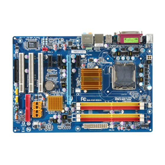
Page 9: Layout Diagram & Jumper Setting
USB Port DDR3 667/800 DIMM1,2 ATX 12V Power Conn. RJ45 Over USB Conn. SYS FAN1 ATX Power Connector Audio Connector Intel P31 Express Chipset PCI-E x16 by 16-laneI RealTek8111C Gigabit LAN Intel ICH7 Chipset PCI-E x1 slots CD Audio In... - Page 10 Jumpers Jumper Name Description Page JBAT CMOS RAM Clear 3-pin Block Keyboard /Mouse/USB Power On Enabled/Disabled 3-pin Block USB Power On Enabled/Disabled 3-pin Block Connectors Connector Name Description Page ATXPWR ATX Power Connector 24-pin Block P.22 ATX12V ATX 12V Power Connector 4-pin Block P.22 PS/2 Mouse &...
-
Page 11: Chapter 2 Hardware Installation
Chapter 2 Hardware Installation WARNING! Turn off your power when adding or removing expansion cards or other system components. Failure to do so may cause severe damage to both your motherboard and expansion cards. Hardware installation Steps Before using your computer, you had better complete the following steps: 1. -
Page 12: Install Cpu
(2) Keyboard /Mouse /USB function Enabled/Disabled: JP1 2-3 Closed KB Power ON Enabled 1-2 Closed KB Power ON Disable (Default) Keyboard/Mouse Power On Setting (3) USB Power On function Enabled/Disabled: JP3 JP2/ JP3 1-2 closed USB Power On Disable 2-3 closed USB Power On Enabled (Default) USB Power-On Setting Install CPU... -
Page 13: About Intel Lga775 Cpu
2-3-2 About Intel LGA775 CPU This motherboard provides a 775-pin DIP, LGA775 Land Grid Array socket, referred to as the LGA775 socket supports Intel Pentium 4 processor in the 775 Pin package utilizes Flip-Chip Land Grid Array (FC-LGA) package technology. -
Page 14: Lga 775 Cpu Installation Guide
2-3-3 LGA 775 CPU Installation Guide Socket Preparation 1. Opening the socket: Note: Apply pressure to the corner with right hand thumb while opening/closing the load lever, otherwise lever can bounce back like a “mouse trap” and WILL cause bent contacts (when loaded) Socket Load Plate Open... - Page 15 3. Visually inspect for bent contacts (Recommend at least 1stpass visual inspection) NOTE: Refer to the Handling and Inspection Module for 1stand 2ndpass inspection details. NOTE: Glove images are for illustrative purposes only. Please consult local safety guidelines for specific requirements NOTE: Recommend not to hold the load plate as a lever, instead hold at tab with left hand, removing the PnP cap with right hand 775- Land LGA Package Insertion...
- Page 16 775- Land Package Removal Open the Load Plate/Lever with both hands: With left hand index finger and thumb to support the load plate edge, engage PnP cap with right hand thumb and peel the cap from LGA775 Socket while pressing on center of PnP cap to assist in removal. Pick up 775-land LGA package: By Vacuum Pen: Place a minimum 9-mm cup at approximately the center of IHS.
- Page 17 Secure/Hook the back side of PnP cap. Snap down the front side to fully secure 7. Close the Socket Intel Reference Thermal Solution Assembly NOTE: Depending on the configuration, Thermal Solution Integration procedure could perform with M/B alone or with M/B in the Chassis.
- Page 18 NOTE: Thermal Solutions that come with IntelR boxed processor use pre-applied thermal interface material Apply Thermal and not grease. Interface Material Remove Heat Sink (HS) from packaging media Place HS onto the LGA775 Socket • Ensure fan cables are oriented on side closest to fan header •...
- Page 19 Intel Reference Thermal Solution Disassembly Rotate fastener cap. turn to un-lock Pull up fastener cap to un-seat 12 Disconnect fan cable from motherboard header Turn fastener caps (4) counter-clock wise 90degrees to the un-locked position • A flat-bladed screwdriver may be used if required Pull up on fastener caps to unseat Manually remove HS with gentle twist motion.
- Page 20 Remove the heatsink from the socket Gently push loose thermal interface material (TIM) to center of processor (pictures 2 and 3) Remove pieces with dry cloth (picture 4) Wipe with dry, lint-free cloth to remove most of the material (picture 5) Wet another lint-free cloth with isopropyl alcohol (IPA) and wipe to clean remaining material (picture 6) Be careful to remove material from gaps between processor and load plate...
- Page 21 − Set on heatsink side or with fan down • The plastic fasteners on the heatsink can be replaced. − Use Shop Intel to order spare fasteners − http://www.shop-Intel.com • To remove a damaged fastener Note: Protective gloves are not required for this procedure −...
- Page 22 Tilt to remove Replacing Fasteners • To replace the fastener − Start with the white prong − Note the “keying” notch feature − Tilt the prong to insert into the heatsink leg. − Holding the white prong without bending it, push the black pin on from the bottom until you hear a single “click”...
-
Page 23: Install Memory
Install Memory This motherboard provides four 240-pin DDR2 DUAL INLINE MEMORY MODULES (DIMM) socket for DDR2 memory expansion available from minimum memory volume of 128MB to maximum memory volume of 4 GB DDR SDRAM and two 240-pin DDR DIMM socket for DDR3 memory expansion available from minimum memory volume of 128MB to maximum memory volume of 4 GB . -
Page 24: Expansion Card
Expansion Cards 2-5-1 Procedure For Expansion Card Installation 1. Read the documentation for your expansion card and make any necessary hardware or software setting for your expansion card such as jumpers. 2. Remove your computer’s cover and the bracket plate on the slot you intend to use. 3. -
Page 25: Pci-Express Slot
2-5-3 PCI Express Slot The P31 Express chipset Based motherboard series offer one PCI-Express x16 graphics slot that offers 4 Gbyte/sec data transfer rate at each relative direction which get 3.5 times of bandwidth more than AGP8X and up to 8 Gbyte/sec concurrent bandwidth at full speed . -
Page 26: Connectors, Headers
Connectors, Headers 2-6-1 Connectors Power Connector (24-pin block): ATXPWR ATX Power Supply connector: This is a new defined 24-pins connector that usually comes with ATX case. The ATX Power Supply allows using soft power on momentary switch that connect from the front panel switch to 2-pins Power On jumper pole on the motherboard. - Page 27 Without this connector might cause system unstable because the power supply can not provide sufficient current for system. (3) PS/2 Mouse & PS/2 Keyboard Connector: KB The connectors are for PS/2 keyboard and PS/2 Mouse input devices. (4) USB Port connector: from USB1, UL1 The connectors are 4-pin connectors that connect USB devices with the 400Mbit / sec data transfer rate to the system board.
- Page 28 FLOPPY (Black) Pin 1 Floppy Drive Connector (9) IDE Connector (40-pin block): IDE This connector supports the provided IDE hard disk ribbon cable. After connecting the single plug end to motherboard, connect the two plugs at other end to your hard disk(s). If you install two hard disks, you must configure the second drive to Slave mode.
-
Page 29: Headers
AC3 data to an external Dolby digital decoder. Use this feature only when your stereo system has digital input function. 2-6-2 Headers (1) Line-Out/MIC Header for Front Panel (9-pin): FP_AUDIO These headers connect to Front Panel Line-out, MIC connector with cable. AUDIO Pin 1 Line-Out, MIC Headers... - Page 30 PWRLED Pin 1 JW FP SPEAK Pin 1 Pin 1 System Case Connections (8) FAN Headers: SYSFAN1, SYSFAN2 (3-pin), CPUFAN (4-pin) These connectors support cooling fans of 350mA (4.2 Watts) or less, depending on the fan manufacturer, the wire and plug may be different. The red wire should be positive, while the black should be ground.
- Page 31 Pin 1 PARALLEL Connector (11) SPDIF Out header: HDMI_SPDIF The SPDIF output is capable of providing digital audio to external speakers or compressed AC3 data to an external Dolby digital decoder. Use this feature only when your stereo system has digital input function. SPDIF HDMI_SPDIF_OUT 、...
-
Page 32: Starting Up Your Computer
Starting Up Your Computer 1. After all connection is made, close your computer case cover. 2. Be sure all the switch are off, and check that the power supply input voltage is set to proper position, usually in-put voltage is 220V∼240V or 110V∼120V depending on your country’s voltage used. -
Page 33: Chapter 3 Introducing Bios
Chapter 3 Introducing BIOS The BIOS is a program located on a Flash Memory on the motherboard. This program is a bridge between motherboard and operating system. When you start the computer, the BIOS program will gain control. The BIOS first operates an auto-diagnostic test called POST (power on self test) for all the necessary hardware, it detects the entire hardware device and configures the parameters of the hardware synchronization. -
Page 34: The Main Menu
The Main Menu Once you enter Award ® BIOS CMOS Setup Utility, the Main Menu (Figure 3-1) will appear on the screen. The Main Menu allows you to select from 12 setup functions and 2 exit choices. Use arrow keys to select among the items and press <Enter> to accept or enter the sub-menu. -
Page 35: Standard Cmos Features
Load Standard Defaults Use this menu to load the BIOS default values for the minimal/stable performance system operation. Save & Exit Setup Save CMOS value changes to CMOS and exit setup. Exit Without Saving Abandon all CMOS value changes and exit setup. Standard CMOS Features The items in Standard CMOS Setup Menu are divided into several categories. -
Page 36: Advanced Bios Features
Cylinder number of cylinders number of heads Head Precomp write precomp Landing Zone landing zone Sector number of sectors Advanced BIOS Features Phoenix – AwardBIOS CMOS Setup Utility Advanced BIOS Features Virus Warning Disabled Item Help CPU L1&L2 Cache Enabled CPU L3 Cache Enabled CPU Feature... - Page 37 The BIOS attempts to load the operating system from the devices in the sequence selected in these items. The settings are Floppy, LS120, Hard disk, CDROM, ZIP100,USB-FDD, USB-ZIP, USB-COROM, Legacy LAN and Disabled. Boot Up Floppy Seek During POST, BIOS will determine if the floppy disk drive installed is 40 or 80 tracks. 360K type is 40 tracks while 760K, 1.2M and 1.44M are all 80 tracks.
-
Page 38: Advanced Chipset Features
Advanced Chipset Features The Advanced Chipset Features Setup option is used to change the values of the chipset registers. These registers control most of the system options in the computer. Phoenix – AwardBIOS CMOS Setup Utility Advanced Chipset Features DRAM Timing Selectable By SPD Item Help * DRAM CAS Latency Time... -
Page 39: Onboard Ide Function
Please refer to section 3-7-1 Onboard Device Function Please refer to section 3-7-2 Onboard Super IO Function Please refer to section 3-7-3 PWR Status after PWR Failure The settings are: Former Status; Always On; Always Off. Init Display First This item allows you to decide to whether activate PCI Slot or PCI Express first. The settings are: PCI Slot, PCI Express. -
Page 40: Onboard Device Function
master driver). If your hard drive and your system software both support Ultra DMA/33 and Ultra DMA/66, select Auto to enable BIOS support. The settings are: Auto, Disabled. IDE HDD Block Mode Block mode is also called block transfer, multiple commands, or multiple sector read/write. If your IDE hard drive supports block mode (most new drives do), select Enabled for automatic detection of the optimal number of block read/writes per sector the drive can support. - Page 41 UART2 Resources Select The optional settings are:Disabled ,3F8/IRQ4, 2F8/IRQ3, 3E8/IRQ4,2E8/IRQ3 and Auto。 UART2 Mode Select This item allows you to determine which InfraRed(IR) function of the onboard I/O chip, this functions uses. IrDA Duplex Mode This field is available when UART Mode is set to either ASKIR or IrDA. This item enables you to determine the infrared function of the onboard infrared chip.
-
Page 42: Power Management Setup
Power Management Setup The Power Management Setup allows you to configure your system to most effectively save energy saving while operating in a manner consistent with your own style of computer use. Phoenix – AwardBIOS CMOS Setup Utility Power Management Setup ACPI Function Enabled Item Help... -
Page 43: Pnp/Pci Configuration
the system will boot up if there’s an incoming call from the modem. Resume by Alarm This function is for setting date and time for your computer to boot up. During Disabled, you cannot use this function. During Enabled, choose the Date and Time Alarm: Date(of month) Alarm You can choose which month the system will boot up. -
Page 44: Pc Health Status
3-10 PC Health Status This section shows the Status of you CPU, Fan, and Warning for overall system status. This is only available if there is Hardware Monitor onboard. Phoenix – AwardBIOS CMOS Setup Utility PC Health Status Shutdown Temperature Disabled Item Help Show PC Health in POST... -
Page 45: Password Setting
Clock Auto Detect PCI This item allows you to enable/disable auto detect PCI Clock. The settings are: Enabled, Disabled. Spread Spectrum This item allows you to set the Spread Spectrum as Enable or Disabled. Linear PCIE X Clock The item allows you to set linear PCIEx clock from a minimum of 100MHz to a maximum of 200MHz. -
Page 46: Load Standard/Optimized Defaults
You determine when the password is required within the BIOS Features Setup Menu and its Security option. If the Security option is set to “System”, the password will be required both at boot and at entry to Setup. If set to “Setup”, prompting only occurs when trying to enter Setup. -
Page 47: Chapter 4 Driver & Free Program Installation
If the menu does not appear, double-click MY COMPUTER / double-click CD-ROM drive or click START / click RUN / type X:\SETUP.EXE (assuming X is your CD-ROM drive). The Intel P31 chipset driver only of Windows 2000 & Windows XP From MAGIC INSTALL MENU you may make 7 selections: 1. -
Page 48: Inf Install Intelp31 Chipset System Driver
4-1 INF Install Intel P31 Chipset System Driver 1. Click INF of the MAGIC INSTALL MENU. 2. Click Next when Intel Chipset Device Software Install Utility appears. 3. Click Yes to accept the license agreement and 4. Finish reading the read me information and continue the installation. -
Page 49: Sound Install Alc883 Hd Codec Audio Driver
SOUND Install ALC662 HD Audio Codec Driver 1. Click SOUND when MAGIC INSTALL 2. Click Next When Realtek High Definition MENU appears Audio driver windows appear 3. Click Finish and restart your computer 4. Manual Sound Effect Setting 5. The mixer. 6. -
Page 50: Lan Install Realtek Megabit Lan Driver
Install RealTek Megabit LAN Driver Click LAN when MAGIC INSTALL MENU Select “Next” . appears. Click Install to install the program. 4. Click Finish to complete the installation. 4-4 PC-CILLIN Install PC-CILLIN 2007 Anti-virus Program 1.Click PC-CILLIN when MAGIC INSTALL MENU 2.Select “Next”... - Page 51 3.This is the license agreement, select "I Accept 4. The preinstallation checkup process. the terms" and Click NEXT. 5.Click Next after you select the features you 6. Click Install after you select to install the want to install and the folder to install it. optional online services.
-
Page 52: Pc-Health Install Myguard Hardware Monitor Utility
3. Click Install to begin the installation. 4. Click Finish to complete the installation. NOTE: MAGIC INSTALL will auto detect file path X:\P31\MYGUARD\SETUP.EXE 4-6 How to Update BIOS Before updating the BIOS, users have to check if the “Miscellaneous Control” of BIOS SETUP has the “Flash Part Write Protect”...