Table of Contents
Advertisement
Quick Links
Installation, Operation and Maintenance
Koolman
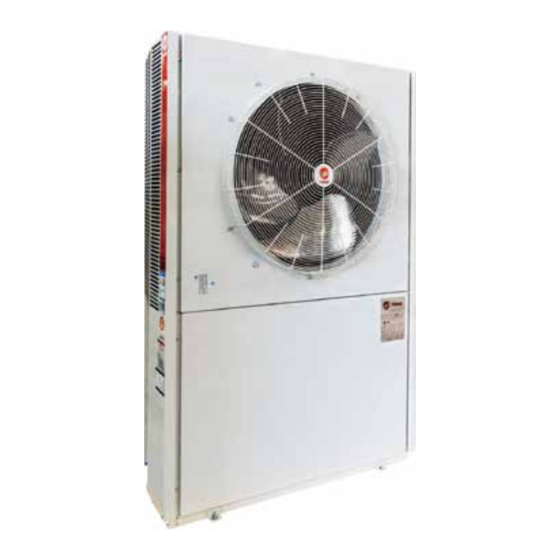
Air-Cooled Chiller and Heat pump
R410A
CGAR/CGAK030~200
Only qualified personnel should install and service the equipment. The installation, starting up, and servicing of
heating, ventilating, and air-conditioning equipment can be hazardous and requires specific knowledge and training.
Improperly installed, adjusted or altered equipment by an unqualified person could result in death or serious injury.
When working on the equipment, observe all precautions in the literature and on the tags, stickers, and labels that are
attached to the equipment.
April 2020
SAFETY WARNING
PKGP-SVX03D-EN
Confidential and proprietary Trane information
500002250200
Advertisement
Table of Contents

Related Manuals for Trane Koolman R410A


Summary of Contents for Trane Koolman R410A
- Page 1 Improperly installed, adjusted or altered equipment by an unqualified person could result in death or serious injury. When working on the equipment, observe all precautions in the literature and on the tags, stickers, and labels that are attached to the equipment. April 2020 PKGP-SVX03D-EN Confidential and proprietary Trane information...
- Page 2 This manual does not aim to summarize the differences of all the water chillers or any possible problem in the installation. If the buyer needs further information or has any special problem, please contact the local sales offices of Trane. NOTICE: There may be warnings and cautions in this manual if applicable.
-
Page 3: Table Of Contents
Contents Model Number Descriptions ........................5 Dimensions ..............................6 Mini casing ............................6 Standard casing ...........................7 Installation ..............................9 Rigging and placement ........................9 Pre-Installation ............................10 General installation checks ......................10 Installation position ..........................10 Water supply pipe ..........................12 Installation example ..........................15 Electrical ..............................16 Electrical wiring ..........................16 Power supply .............................16 Electrical data -50Hz ...........................17 A: Mini type ............................17... - Page 4 Table of Contents Antifreezing function in winter ......................30 Antifreezing of plate type heat exchanger ..................30 High voltage protection of plate type heat exchanger ..............30 Overload protection of motor ......................30 Flow protection ..........................30 Running operation ..........................30 Thermo probe (TH1) .........................30 Cooling mode: ...........................31 Heating mode: ...........................31 Ambient temperature operation limit .....................31 Controller ..............................32...
-
Page 5: Model Number Descriptions
Model Number Descriptions Digits 1,2,3 CGA = Air-Cooled Chiller and Heat Pump Digit 4 Model K = Cooling Only R = Heat Pump Digits 5,6,7 Model Digit 8 Power Supply 5 = 380V/50Hz/3ph (For Model 030,050,060,07 5,100,120,150,200) 6 = 220V/50Hz/1ph (for 030 with single compressor and 060 with double compressors) Digit 9 Manufacturing Code (defaulted by factory) R = R410A... -
Page 6: Dimensions
Dimensions Mini casing CGAK/R-0305R/0306R/0505R/0605R (Unit: mm) Ø1"Water inlet Ø1"Water outlet CGAK/R-0705 R (Unit: mm) Inlet: PT RP 1¼" Outlet: PT RP 1¼" PKGP-SVX03D-EN... -
Page 7: Standard Casing
Dimensions Standard casing CGAK/R-0606R/1005R (Unit: mm) 1290 Ø40 connect wire hole Inlet RC 1¼" Outlet RC 1¼" Drain Hole CGAK-1205R (Unit: mm) 1990 Ø40 connect wire hole Drain Hole 1/2" Inlet PT RC 1-1/4" Outlet PT RC 1-1/4" PKGP-SVX03D-EN... - Page 8 Dimensions CGAR-1205R (Unit: mm) 1990 Ø40 connect wire hole Ø40 connect wire hole Outlet RC 1¼" Inlet RC 1¼" Drain Hole 1/2" 1550 CGAR/K-1505R/2005R (Unit: mm) 1990 Ø40 connect wire hole Inlet Drain hole 1/2” Outlet 1550 PKGP-SVX03D-EN...
-
Page 9: Installation
Installation Rigging and placement Please use the forklift with proper capacity tonnage to transport and handle, for weight of each model please refer to reference table 1. Table 1. Model The maximum net weight (kg)≈ 0305R 0306R 0505R 0605R 0606R 0755R 1005R 1205R... -
Page 10: Pre-Installation
Installation Pre-Installation General installation checks If the content of the machine's name plate is the same as that of the order. • If there is any damage or material shortage during transportation of the unit; if yes, please notify the 1630 deliverer timely. - Page 11 Installation ≥ 500 ≥ 300 Air Flow Air Flow Air Flow Air Flow ≥500 ≥300 Air Flow Air Flow Mini-Koolman Figure 3. Service and Maintenance Space Requirement PKGP-SVX03D-EN...
-
Page 12: Water Supply Pipe
Installation Water supply pipe Evaporator piping: • Clean out all cold water piping. • Connect the evaporator piping. • Exhaust the air in the cold water system at the highest point of this system piping. • Install pressure meters, temperature meters and valves at the inlet piping and outlet piping. •... - Page 13 Installation Make-up water Expansion tank Water intake Oil-return inlet Manual gate valve Automatic air vent Manual gate valve Balancing valve ball valve Thermometer Flow switch Filter Shockproof hose Manometer Water intake Shockproof gasket Water outlet Figure 4. Installation diagram for typical piping accessories (the model of this diagram is CGAR100) PKGP-SVX03D-EN...
- Page 14 Installation Make-up water c ` r Z P Tee valve c ` r Z O c ` r Z c ` r Z S Water drainage c ` r Z R Direct return c ` r Z Q Manual gate valve Reversed return Thermometer Flow switch...
-
Page 15: Installation Example
Installation Installation example Fan coil X4 pressurised Primary Unit water tank Makeup water valve water strainer water Automatic air vent Direct Reversed Drain Valve return return Water drainage flow Shockpro Thermometer switch Electric heater Shut-off of hose Note: the automatic exhaust valve shall be set at the highest point of the piping Figure 6. -
Page 16: Electrical
Electrical Electrical wiring • Connect the power wiring to the terminal block (TB) of the water chiller distribution cabinet. • Connect the control panel (installed indoor) and the master control board of the primary water chiller with connecting line of control panel. •... -
Page 17: Electrical Data -50Hz
Electrical Electrical data -50Hz A: Mini type Minimum specification Minimum Full load Rated Rated Recommended Recommended of the power current of the Power supply current of the current of the current fuse circuit breaker supply copper Model water unit (V/Hz/Ph) water pump compressor of the fan... -
Page 18: Wiring Diagram
Wiring Diagram The following wiring diagrams are only for reference, and the supplied wiring diagram Included in the unit shall prevail. CGAR/K0305R*/0505R*/0605R* PKGP-SVX03D-EN... - Page 19 Wiring Diagram CGAR/K0306* PKGP-SVX03D-EN...
- Page 20 Wiring Diagram CGAR/K0606R* PKGP-SVX03D-EN...
- Page 21 Wiring Diagram CGAR/K0755R* PKGP-SVX03D-EN...
- Page 22 Wiring Diagram CGAR/K1005R* 1205R/1505R*/2005R* PKGP-SVX03D-EN...
-
Page 23: Pre-Start-Up
Pre-Start-up Voltage range Power supply of the water chiller must conform to the operation power supply marked on the name plate, and the power voltage & unbalances between each phase must be within the following scope. Gauge the voltages between each phase, readings of which must be within the acceptable voltage tolerance (±10%) marked on the name plate. -
Page 24: Check The Following Items Before Start
Pre-Start-up Check the following items before start • Check connection of all wiring, and all electric connection points shall be kept clean and locked tightly. • Check if the power voltage of the water chiller is normal. • Fully fill the cold water loop with water, and the exhaust valve of the system shall be kept open during filling, which shall be closed after the loop being filled fully. - Page 25 Pre-Start-up Figure 7. Unit Hydraulic curve diagram CGAR0305 CGAR0306 1.146 1.337 1.528 1.719 1.91 2.101 2.292 2.483 2.674 1.07 1.25 1.43 1.61 1.79 1.97 2.15 2.33 2.51 Water Flow :m Water Flow :m CGAR0605 CGAR0505 1.344 1.568 1.792 2.016 2.24 2.464 2.688 2.912...
-
Page 26: Unit Settings
Pre-Start-up 2.74 3.19 3.65 4.10 4.56 5.02 5.47 5.93 4.03 4.70 5.37 6.04 6.71 7.38 8.05 :m :m Water Flow Water Flow CGAR1505 CGAR2005 4.76 5.56 6.35 7.15 7.94 8.73 9.53 5.47 6.38 7.29 8.20 9.11 10.02 10.93 11.84 :m :m Water Flow Water Flow... -
Page 27: System Position Setup
To prevent antifreezing alarm at low refrigerating return water temperature setting, please increase the addition of antifreezing agent or use a large flow water pump in the water system. Please consult Trane after-sales service personnel to modify the antifreezing setting. PKGP-SVX03D-EN... -
Page 28: Start-Up And Operation
Start-up and Operation Starting procedures • Switch the water chiller power on, press MODE button on the control panel to choose refrigerating or heating, and then press ON/OFF button to start the water chiller operation. • Keep the water chiller operating for more than 30MIN, and when system operation is stable, check the following items to ensure the normal operation of the water chiller: 1.Check whether the water flow and pressure of the water chiller are stable in a normal range. -
Page 29: Long-Term Shutdown
Start-up and Operation Long-term shutdown • For long-term shutdown, the following procedures shall be carried out before system halt: 1.Check whether cooling agent piping leaks, and if so, be sure to have it repaired. 2.Maintain water pump and air conditioning plant as proposed by manufacturer. 3.Discharge all circulating water from the system, unscrew dewatering outlet in the water supply and return circuit, dismantle side panel of the water chiller, and unscrew the dewatering outlet in the bottom of water pump and plate type heat exchanger so as to ensure complete... -
Page 30: High Voltage Protection (Hp1, Hp2)
Start-up and Operation High voltage protection (HP1, HP2) A high voltage switch gear is provided to protect the water chiller. When high voltage exceeds 602±22psig(4.15±0.15MPa), compressor operation is stopped, and when the pressure is dropped to 479±22psig(3.303±0.152MPa), compressor operation is automatically restored. Antifreezing function in winter In winter, when the water chiller is in a standby state, if water temperature is below the winter antifreezing temperature setting, the water chiller automatically will enter antifreezing operation,... -
Page 31: Cooling Mode
Start-up and Operation Cooling mode: Dual system When the system is started, the water pump shall run at once. After a period of 2MIN, the water pump continues to run. When return water temperature reaches or more, No.1 compressor will be started. -
Page 32: Controller
Controller Wired controller PKGP-SVX03D-EN... -
Page 33: Operation And Display Panel
Controller Operation and display panel Control panel 1. On/Off button 2. Mode button, controlling refrigeration and heating. Mode setting must be carried out in a shutdown state. 3. Fault resetting button, pressed for manual resetting when a failure alarm is given. 4. -
Page 34: Troubleshooting And Diagnostics
Troubleshooting and Diagnostics Troubleshooting checklist "EE" code is displayed as controller and control panel communication fails. A total of 13 fault input alarm switches, as well as 1 failure output alarm switch, are provided for single compressor system Central S/N Input port Fault Description Type Code Controller Troubleshooting... - Page 35 Troubleshooting and Diagnostics A total of 17 failure input alarm switches, as well as 1 fault output alarm switch, are provided for dual compressor system Central Controller S/N Input port Fault Description Type Code Troubleshooting Code Return water temperature sensing All peripherals are to be closed.
- Page 36 Troubleshooting and Diagnostics A. Compressor cannot be started, but remains silent. "EE" code is displayed as controller and control panel communication fails. A total of 13 fault input alarm switches, as well as 1 failure output alarm switch, are provided for single compressor system Possible cause Solution...
- Page 37 Troubleshooting and Diagnostics D. Too short running period of compressor Possible cause Solution Check the following items: Control circuit is intermittently connected. a. Poor contact of contactor d. Loose wiring connection E. Compressor runs without stop Possible cause Solution Power of the water chiller is not enough to bear a load Check causes that lead to excessive load.
- Page 38 Troubleshooting and Diagnostics H. Inadequate air cooling capacity Possible cause Solution I n s u ff i c i e n t c o o l a n t ( l ow s u p e r h e a t d e g r e e a n d Supply coolant.
- Page 39 Troubleshooting and Diagnostics L. Too high discharge pressure Possible cause Solution Insufficient of excessive cooling air, flow choking Clean the coiler and check whether fan and motor are normal. Air or non-condensed gas present in the system Vacuumize the system and re-fill it with coolant. (abnormally hot condenser) Excessive coolant (high supercooling degree, low Reclaim redundant coolant.
- Page 40 For more information, please visit trane.com or tranetechnologies.com. Trane has a policy of continuous product and product data improvement and reserves the right to change design and specifications without notice. We are committed to using environmentally conscious print practices.