Table of Contents
Advertisement
Installation, Operation,
and Maintenance
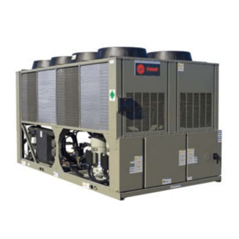
Air-Cooled Scroll Chillers
Model CGAM
20 – 130Tons — Made in USA
Only qualified personnel should install and service the equipment. The installation, starting up, and
servicing of heating, ventilating, and air-conditioning equipment can be hazardous and requires specific
knowledge and training. Improperly installed, adjusted or altered equipment by an unqualified person could
result in death or serious injury. When working on the equipment, observe all precautions in the literature
and on the tags, stickers, and labels that are attached to the equipment.
June 2012
SAFETY WARNING
CG-SVX17E-EN
Advertisement
Table of Contents

Related Manuals for Trane CGAM


Summary of Contents for Trane CGAM
- Page 1 Installation, Operation, and Maintenance Air-Cooled Scroll Chillers Model CGAM 20 – 130Tons — Made in USA SAFETY WARNING Only qualified personnel should install and service the equipment. The installation, starting up, and servicing of heating, ventilating, and air-conditioning equipment can be hazardous and requires specific knowledge and training.
- Page 2 ALWAYS refer to the appropriate MSDS sheets and Responsible Refrigerant Practices! OSHA guidelines for information on allowable Trane believes that responsible refrigerant practices are personal exposure levels, proper respiratory important to the environment, our customers, and the air protection and handling recommendations.
- Page 3 Introduction Overview This manual covers the installation, operation and maintenance of the CGAM units. Revision Summary CG-SVX17E-EN The following points describe the changes to this revision of the manual: •...
-
Page 4: Table Of Contents
Oil System Operation (CGAM) ........ - Page 5 Controls Interface ..............101 CH530 Communications Overview .
-
Page 6: Model Number Descriptions
Model Number Descriptions Nameplates Compressor Nameplate The CGAM unit nameplates are applied to the exterior The compressor nameplate provides the following surface of the control panel door for 20-70Ton sizes.The information: 80-120Ton sizes have a nameplate on a support beam to •... -
Page 7: Unit Model Number Description
Unit Model Number Description Digits 1-4— Chiller Model Digit 21— Evaporator Digit 31— Remote Interface Application (Digital Comm) CGAM= Air-Cooled Scroll Packaged Standard Cooling (42 to 65°F/5.5 No Remote Digital Chiller to 18°C) Communication Digits 5-7— Unit Nominal Ton LowTemperature Processing... -
Page 8: Compressor Model Number Description
Compressor Model Digit 45— Phase Reversal Protection Number Description Phase Reversal Protection Digit 46— Shipping Package Digits 1-4— Compressor Model No Skid (Standard) CSHD= Light Commercial Unit Containerization Package CSHN= Commercial Digit 47— Performance Test Digits 5-7— Capacity Options 125 = CSHD No PerformanceTest 161 =... -
Page 9: General Information
Unit Description Figure 3. CGAM “V” 40-70 Ton Configuration The CGAM units are scroll type, air-cooled, liquid chillers, designed for installation outdoors.The 20-35 ton units have a single independent refrigerant circuit, with two compressors per circuit.The 40 ton and larger units have 2 independent refrigerant circuits, with two compressors per circuit.The CGAM units are packaged with an... -
Page 10: Accessory/Options Information
General Information Accessory/Options Information Figure 6. V 40-70 ton - ship with location - isolator and prop rod Check all the accessories and loose parts which are shipped with the unit against the original order. Included in these items will be water vessel drain plugs, rigging diagrams, electrical diagrams, and service literature, which are placed inside the control panel and/or starter panel for shipment. - Page 11 General Information Figure 7. W 80-130 ton - ship with location - isolator and prop rod Prop Rod Elastomeric Isolators Seismic Isolators CG-SVX17E-EN...
-
Page 12: General Data
General Data General Data Table 1. General Data - 60 Hz - IP Size Compressor Number 20+20 Tonnage/circuit¹ 10+10 13+13 15+15 15+20 10+10 13+13 15+15 15+20 20+20 20+25 25+25 25+30 30+30 Evaporator Water storage (gal) 10.3 11.5 11.5 12.3 Min. flow (gpm) Max. - Page 13 General Data Table 2. General Data - 60 Hz - SI Size Compressor Number 20+20 Tonnage/circuit¹ 10+10 13+13 15+15 15+20 10+10 13+13 15+15 15+20 20+20 20+25 25+25 25+30 30+30 Evaporator Water storage 12.1 15.5 18.9 28.4 26.5 34.1 39.0 43.5 43.5 46.6 Min.
- Page 14 General Data Table 3. General Data - 50 Hz - IP Size Compressor Number Tonnage/circuit¹ 10+10 13+13 15+15 15+20 10+10 13+13 15+15 15+20 20+20 20+25 25+25 25+30 30+30 Evaporator Water storage (gal) 10.3 11.5 11.5 Min. flow (gpm) Max. flow (gpm) Water connection (in) Condenser Quantity of coils...
- Page 15 General Data Table 4. General Data - 50 Hz - SI Size Compressor Number Tonnage/circuit¹ 10+10 13+13 15+15 15+20 10+10 13+13 15+15 15+20 20+20 20+25 25+25 25+30 30+30 Evaporator Water storage 12.1 15.5 18.9 28.4 26.5 34.1 39.0 43.5 43.5 Min.
-
Page 16: Pre-Installation
A list of the contractor responsibilities typically associated and that it is properly equipped. Compare the information with the unit installation process is provided. which appears on the unit nameplate with the ordering Trane Trane and submittal information. Supplied Supplied... -
Page 17: Unit Dimensions/Weights
(429 mm) outlet 113.8 in (2890 mm) Water connections are 1.7 in (44 mm) from the end. Figure 9. CGAM 20 and 26 ton - service clearances and mounting locations Service and Airflow Clearance Mounting Locations Distance from edge to middle of mounting hole 1.5 in (38 mm) - Page 18 The number of fans shown does not represent Water connections are 1.6 in (40 mm) the number of fans installed. from unit end. Figure 11. CGAM 30 and 35 ton - service clearances and mounting locations Service and Airflow Clearance Mounting Locations...
- Page 19 (367 mm) Water connections are even with unit end. Note: When facing the control panel, circuit 1 is on the right side of unit. Figure 13. CGAM 40 and 52 ton- service clearances and mounting locations Mounting Locations Service and Airflow...
- Page 20 Water connections are even with unit end. the number of fans installed. Note: When facing the control panel, circuit 1 is on the right side of unit. Figure 15. CGAM 60 and 70 ton - service clearances and mounting locations Mounting Locations Service and Airflow...
- Page 21 Water connections are 5.5 in (139 mm) from unit end. Note: When facing the control panel, circuit 1 is on the right side of unit. Figure 17. CGAM 80 and 90 ton - service clearances and mounting locations Mounting Locations Service and Airflow...
- Page 22 Note: When facing the control panel, circuit 1 is on the right side of unit. Figure 19. CGAM 100, 110 and 120 ton- service clearances and mounting locations Mounting Locations Service and Airflow...
- Page 23 Water connections are 25 in (635 mm) from unit end. Note: When facing the control panel, circuit 1 is on the right side of unit. Figure 21. CGAM 130 ton- service clearances and mounting locations Mounting Locations Service and Airflow...
- Page 24 Unit Dimensions/Weights Unit Dimensions - Optional Pump Package, Buffer Tank, Partial Heat Recovery Figure 22. Sizes 20 and 26 ton — pump package, buffer tank, partial heat recovery Control Panel 84.7 in (2151 mm) Pump Package BufferTank Wire Connection Compressor Pump Package 20.8 in (529 mm) 92.4 in (2348 mm)
- Page 25 Unit Dimensions/Weights Figure 24. Sizes 40 and 52 ton — pump package, buffer tank, partial heat recovery Pump Package Control Panel Wire Connection Compressor Buffer Tank 84.8 in Pump (2155 mm) Package 23.7 in (602 mm) Lifting 88.6 in (2250 mm) Locations 89.9 in (2282 mm) Length w/ PP or PHR...
- Page 26 Unit Dimensions/Weights Figure 26. Sizes 80 and 90 ton — pump package, buffer tank, partial heat recovery Compressors Buffer Tank Pump Package VFD Control Panel 92 in (2337 mm) Pump Package Wire Connection Lifting 29.6 in (752 mm) Locations 89 in (2261 mm) 89.2 in (2265 mm) Length w/ buffer tank 144 in (3658 mm)
- Page 27 Unit Dimensions/Weights Figure 28. Size 130 ton — pump package, buffer tank, partial heat recovery Compressors Buffer Tank Pump Package Pump Package VFD Control Panel 92 in (2337 mm) Wire Connection 29.6 in (752 mm) Lifting 89 in (2261 mm) Locations 149.8 in (3804 mm) 203.0 in (5156 mm)
- Page 28 Unit Dimensions/Weights Pump Package, Partial Heat Recover and Buffer Tank - Water Connections Figure 29. CGAM 20 and 26 ton - pump package, buffer tank, partial heat recovery unit water connections Pump Package Buffer Tank Partial Heat Recovery Chilled Chilled...
- Page 29 Unit Dimensions/Weights Figure 31. CGAM 40 and 52 ton- pump package, buffer tank, partial heat recovery unit water connections Pump Package Buffer Tank Partial Heat Recovery Heating outlet Heating inlet Chilled Chilled water water inlet inlet Chilled Chilled water water outlet 54.8in...
- Page 30 Unit Dimensions/Weights Figure 33. CGAM 80 and 120 ton- pump package, buffer tank, partial heat recovery unit water connections Pump Package Partial Heat Recovery (with or without buffer tanks) 1.8 in (46 mm) Heating outlet Heating inlet Chilled water inlet 28.9 in (733 mm)
- Page 31 Unit Dimensions/Weights Weights Table 5. Weights - 60 Hz Base Unit Base Unit Base Unit Partial Heat Without Pump With Pump With Pump and Buffer Tank Recovery - add Copper - Tons Shipping Operating Shipping Operating Shipping Operating Shipping Operating 2185 2207 1002...
-
Page 32: Installation - Mechanical
Once in place, the unit must be equipment or property-only damage. level within 1/4” (6.4 mm) over its length and width.The Trane Company is not responsible for equipment Lifting using either a single spreader bar or an H-type problems resulting from an improperly designed or spreader is acceptable. - Page 33 Crane lift point must move to the unit CG to produce a level unit lift Crane lift point “H” type spreader bar Figure 38. CGAM W 80-130 Ton Rigging Lifting Straps to unit base Figure 36. CGAM slant 20-35 ton rigging CG-SVX17E-EN...
- Page 34 Installation - Mechanical Table 7. CGAM center of gravity (in) - 60 Hz Aluminum fins Copper fins With Pump With Pump Pkg, With Pump With Pump Pkg, Base Unit Package Buffer Tank Base Unit Package Buffer Tank Unit (tons) Units without partial heat recovery...
- Page 35 Installation - Mechanical Table 8. CGAM center of gravity (in) - 50 Hz Aluminum fins Copper fins With Pump With Pump Pkg, With Pump With Pump Pkg, Base Unit Package Buffer Tank Base Unit Package Buffer Tank Unit (tons) Units without partial heat recovery...
-
Page 36: Unit Isolation And Leveling
Seismically Rated Isolator Installation tighten the isolator mounting bolts. Seismically rated isolators are required for OSHPD Figure 39. CGAM Elastomeric isolator seismically rated units, and optional for IBC seismically rated units. Isolators are identified by part number and color. See B NC TAP Table 10, p. - Page 37 Installation - Mechanical Figure 40. MSSH seismically rated isolator Figure 41. M2SS seismically rated isolator 1 1/2 11 1/4 1 1/8 5/8 EQUIPMENT 5/8 EQUIPMENT CLAMP DOWN NUT 13/16 DIA HOLE FOR CLAMP DOWN NUT ATTACHMENT TO 13/16 DIA HOLE FOR CONCRETE (4 TYP) ATTACHMENT TO CONCRETE (4 TYP)
- Page 38 Installation - Mechanical 1. Set isolators on mounting surface, ensuring that all isolator centerlines match the submittal drawing. All Installation of Seismically Rated Isolators isolator base plates (B) must be installed on a level Figure 42 Figure 43, p. 38 for reference.
-
Page 39: Mounting Point Locations And Weights
Installation - Mechanical Mounting Point Locations and Weights Figure 45. Mounting Point Locations Table 11. Elastomeric isolator locations - base unit - with or without partial heat recovery Location Size (ton) RDP-3 RDP-3 RDP-3 RDP-3 20-26 Grey 60 Grey 60 Grey 60 Grey 60 RDP-4... - Page 40 Installation - Mechanical Table 13. Elastomeric isolator locations - with pump package and buffer tank option - with or without partial heat recovery Location Size (ton) RDP-3 RDP-3 RDP-4 RDP-4 20-35 Grey 60 Grey 60 Green 63 Green 63 RDP-4 RDP-4 RDP-4 RDP-4...
- Page 41 Installation - Mechanical Table 15. Point weights (lbs) - 60 Hz - base unit Isolator location Aluminum Fins Copper Fins Size (tons) Without partial heat recovery 1027 1035 1152 1036 1198 1246 1081 1156 1210 1283 1130 1198 1252 1319 1118 1210 1239...
- Page 42 Installation - Mechanical Table 16. Point weights (lbs) - 60 Hz - with pump package Isolator location Aluminum Fins Copper Fins Size (tons) Without partial heat recovery 1173 1182 1214 1109 1009 1336 1244 1146 1054 1225 1146 1030 1349 1279 1165 1096...
- Page 43 Installation - Mechanical Table 17. Point weights (lbs) - 60 Hz - with pump package and buffer tank options Isolator location Aluminum Fins Copper Fins Size (tons) Without partial heat recovery 1728 1650 1867 1650 1741 1653 1884 1650 1885 1782 2074 1789...
- Page 44 Installation - Mechanical Table 18. Point Weights (lbs) - 50 Hz - base unit Isolator location Aluminum Fins Copper Fins Size (tons) Without partial heat recovery 1027 1035 1152 1036 1198 1246 1081 1156 1210 1283 1130 1198 1252 1319 1118 1210 1239...
- Page 45 Installation - Mechanical Table 19. Point Weights (lbs) - 50 Hz - with pump package (continued) Isolator location Aluminum Fins Copper Fins Size (tons) With partial heat recovery 1170 1181 1186 1111 1309 1244 1133 1068 1197 1148 1019 1322 1279 1152 1109...
-
Page 46: Evaporator Piping
Locate the unit near a large capacity drain for water vessel Evaporator water connections are grooved. drain-down during shutdown or repair. Evaporators are Thoroughly flush all water piping to the CGAM unit before provided with drain connections. Refer to “Water Piping. ” making the final piping connections to the unit. -
Page 47: Entering Chilled Water Piping
145 Psig. You MUST drain the See schematics in CGAM-SVE01*-EN for more details. system FIRST before releasing the pressure. Failure to do so could result in water spray which could cause Note: Use caution when connecting the auxiliary equipment and/or property damage. - Page 48 Installation - Mechanical Figure 47. BPHE label locations 20T BPHE - P80 40T BPHE - DP200 BPHE LABEL LOCATION BARCODE BPHE LABEL LOCATION BARCODE ADDITIONAL INSULATION ADDITIONAL INSULATION ROLL BACK THE INSULATION 26/30/36T BPHE - P120 52-130T BPHE - DP400 BPHE LABEL LOCATION BPHE LABEL...
-
Page 49: Pressure Drop Curves
Installation - Mechanical Pressure Drop Curves For overlapping pressure drop curves, see General DataTables in section “General Information, ” p. 9 for limit values Figure 48. Total unit pressure drop curves (60 Hz) 1 2 0 0 4 0 0 3 0 0 7 0 0 8 0 1 3 0 1 0 0... -
Page 50: Freeze Protection
For this option the pump must to be controlled by -20°F) the CGAM unit and this function must be validated. a. Shut off the power supply to the unit and to all b. Water circuit valves need to stay open at all times. - Page 51 Installation - Mechanical Table 22. Low Evap Refrigerant Temp Cutout and Low Water Temp Cutout ETHYLENE GLYCOL PROPYLENE GLYCOL Min Chilled Water Set Min Chilled Water Set Refrig Water Point [F] Refrig Water Point [F] Solution Temp Temp Solution Temp Temp Freeze Cutout...
- Page 52 Installation - Mechanical Table 22. Low Evap Refrigerant Temp Cutout and Low Water Temp Cutout (continued) ETHYLENE GLYCOL PROPYLENE GLYCOL Min Chilled Water Set Min Chilled Water Set Refrig Water Point [F] Refrig Water Point [F] Solution Temp Temp Solution Temp Temp Freeze...
-
Page 53: Performance Adjustment Factors
Installation - Mechanical Performance Adjustment Factors Concentration and type of glycol used will affect unit performance. If operating conditions, including concentration of freeze inhibitor, have changed since the unit was ordered, contact sales representative to rerun selection. See Figure 50, p. -
Page 54: Partial Heat Recovery
• Manual air vent water treatment, if any, is required. Trane assumes no responsibility for equipment failures which result from • Drain pipe untreated or improperly treated water, or saline or Water circulating inside the heat recovery heat exchanger brackish water. -
Page 55: Partial Heat Recovery Freeze Protection
Figure 56. Partial Heat Recovery Piping Recommendations CGAM Unit Note: In addition to those recommended for field piping, the CGAM unit includes factory installed manual air vent and water drain valve with partial heat recovery option. See Figure 81, p. 96 through Figure 83, p. -
Page 56: Partial Heat Recovery Pressure Drop Curves
Installation - Mechanical Partial Heat Recovery Pressure Drop Curves Figure 58. Partial heat recovery pressure drop curve — Figure 57. Partial heat recovery pressure drop curve — 50 Hz 60 Hz 90/100/110 120/130 80/90/100 60/70 110/120 52/60 40/52 30/35 26/30 20/26 PHR Water Flow Rate (gpm) PHR Water Flow Rate (gpm) -
Page 57: Dual High Head Pump Package
Vibration Eliminator Note: Speed command is also available for customer- provided variable flow input. Isolate unit for initial water loop cleaning Figure 60 for CGAM pump package unit schematic. Figure 60. Pump package unit schematic INLET OUTLET Water Line Insulated Water Line Table 26. - Page 58 Installation - Mechanical Pressure Drop Information - Units with Optional Pump Package Water only Factory Installed Pump Package - Pump Curves. Figure 61 through Figure 64, p. 59 show manufacturer pump curves for factory-installed pump package. Figure 61. Pump curve - 20-52T - water only Figure 62.
- Page 59 Installation - Mechanical Figure 63. Pump curve - 80-110T - water only Figure 64. Pump curve - 120-130T - water only CG-SVX17E-EN...
- Page 60 FLOW RATE (GPM) System Head Pressure. Figure 66 for the system head pressure available. Note: System Head Pressure = Pump Pressure - Component Pressure) Figure 66. CGAM pump package available head pressure - water only 026/030 FLOW RATE (GPM) CG-SVX17E-EN...
- Page 61 Installation - Mechanical Unit with Optional Pump Package Systems - Pump Package Requirements Glycol The following requirements must be met for proper If using glycol in system, apply adjustment factors to operation of pump package: pressure drops per the following formulas: •...
- Page 62 Installation - Mechanical Expansion Tank - Maximum Loop Volume Expansion tanks supplied as part of the pump package Important: Chilled waterside pressure relief valve is option will allow loop expansion due to ambient designed to open at 226 ft. If relief valve is fluctuations for maximum loop volumes shown in opening at lower pressures, verify system Table 29...
- Page 63 Installation - Mechanical Table 30. Maximum loop volume - liters (external to the chiller) Maximum Ambient = 100°F Maximum Ambient = 115°F % Ethylene Glycol % Propylene Glycol % Ethylene Glycol % Propylene Glycol Size Water 10 45 Water 10 WITHOUT BUFFER TANK 1813 1639 1121...
-
Page 64: Installation - Electrical
Installation - Electrical General Recommendations All wiring must comply with local codes and the National Electric Code.Typical field wiring diagrams are included at the end of the manual. Minimum circuit ampacities and other unit electrical data are on the unit nameplate. See the unit order specifications for actual electrical data. -
Page 65: Electrical Data Tables
Installation - Electrical Electrical Data Tables Table 31. Electrical Data - 60 Hz No pump Pump Unit Motor Cond Size Rated Number Power Compressor Compressor Power Circuits Comp Fans (kw) RLA¹ LRA² MOPD 208/60/3 39-39 267-267 230/60/3 39-39 267-267 380/60/3 22-22 160-160 460/60/3... - Page 66 Installation - Electrical Table 31. Electrical Data - 60 Hz No pump Pump Unit Motor Cond Size Rated Number Power Compressor Compressor Power Circuits Comp Fans (kw) RLA¹ LRA² MOPD 208/60/3 74-74/74-74 485-485/485-485 230/60/3 67-67/67-67 485-485/485-485 380/60/3 40-40/40-40 260-260/260-260 460/60/3 33-33/33-33 215-215/215-215 575/60/3...
- Page 67 Installation - Electrical Table 32. Lug Range Size - 60 Hz No Pump Pump Terminal Std Fault High Fault Terminal Std Fault High Fault Unit Size Rated Power Blocks Ckt Breaker¹ Ckt Breaker¹ Blocks Ckt Breaker¹ Ckt Breaker¹ 208/60/3 #6 - 350 MCM #14 - 1/0 #14 - 1/0 #6 - 350 MCM...
- Page 68 Installation - Electrical Table 32. Lug Range Size - 60 Hz No Pump Pump Terminal Std Fault High Fault Terminal Std Fault High Fault Unit Size Rated Power Blocks Ckt Breaker¹ Ckt Breaker¹ Blocks Ckt Breaker¹ Ckt Breaker¹ 208/60/3 #4 - 500 MCM 3/0 - 500 MCM²...
- Page 69 Installation - Electrical Table 33. Electrical Data - 50Hz Unit Rated Number Fan Motor Cond Fan Compressor Compressor Size Power Circuits Comp Fans Power (kW) RLA¹ ² LRA¹ ³ MOPD 400/50/3 17-17 142-142 400/50/3 21-21 158-158 400/50/3 27-27 160-160 400/50/3 27-33 160-215 400/50/3...
-
Page 70: Installer-Supplied Components
Installation - Electrical Installer-Supplied Components conduits and connected to the terminal blocks or HACR type breakers. Refer to Table 35. Customer wiring interface connections are shown in the To provide proper phasing of 3-phase input, make electrical schematics and connection diagrams that are connections as shown in field wiring diagrams and as shipped with the unit.The installer must provide the stated on the WARNING label in the starter panel. -
Page 71: Partial Heat Recovery Power Supply
Installation - Electrical Table 35. Power Entrance “V” Configuration 40-70Ton Incoming “Slant” Configuration 20-35Ton Voltage Power Power Voltage Incoming Power Power “W” Configuration 80-130Ton Incoming Power Low Voltage Power Partial Heat Recovery Power Supply Note: If partial heat recovery heat exchanger is drained, the heater must be turned off in order to avoid The partial heat recover heat exchanger is insulated from damaging the partial heat recovery heat exchanger. -
Page 72: Interconnecting Wiring
Tracer, Start Inhibited by Low AmbientTemp, and Ice Note: If pump control is used for freeze protection then Building complete. the pump MUST be controlled by the CGAM CH530 control. If another method of freeze protection is used (i.e. glycol, heaters, purge, etc) then the pump NOTICE: may be controlled by another system. - Page 73 The default assignments for the four available relays of the panel and wire through the appropriate relays (terminals CGAM Alarm and Status Package Option are: on 1A13. Provide wiring (switched hot, neutral, and ground connections) to the remote annunciation devices.
-
Page 74: Low Voltage Wiring
Installation - Electrical Low Voltage Wiring NOTICE: Equipment Damage! WARNING Do NOT enable/disable the chiller by removing water Proper Field Wiring and Grounding flow or equipment damage can occur. Required! All field wiring MUST be performed by qualified Ice Building Option personnel. - Page 75 Installation - Electrical Connect leads from 6K6 to the proper terminals of 1A16. 2-10 VDC and 4-20 mA shall each correspond to an EDLS Refer to the field diagrams which are shipped with the unit. range with a minimum of 0% and a maximum of 100%.The following equations exist.
-
Page 76: Percent Capacity Output Option
Installation - Electrical Chilled Water Reset (CWR) the same as the Return Reset equation except on selection of Constant Return Reset, the MP will automatically set CH530 resets the chilled water temperature set point Ratio, Start Reset, and Maximum Reset to the following. based on either return water temperature, or outdoor air RATIO = 100% temperature. -
Page 77: Communications Interface Options
Installation - Electrical Communications Interface options Tracer Communications Interface include both mandatory and optional network variables as established by the LonTalk Functional Chiller Profile 8040. This option allows theTracer CH530 controller to exchange Installation Recommendations information (e.g. operating setpoints and Auto/Standby commands) with a higher-level control device, such as a •... -
Page 78: Bacnet Communications Interface For Chillers (Bci-C)
Installation - Electrical BACnet Communications Interface for Chillers (BCI-C) The optional BACnet Communication Interface for Chillers Interoperability Building Blocks (Annex K) (BCI-C) is comprised of aTracer UC400 controller with Supported interface software. It is a non-programmable Data Sharing Description BIBB communications module that allows the RTWD or RTUD Data Sharing-COV-B (DS-COV-B) unit to communicate on a BACnet communications... - Page 79 Installation - Electrical Object Types Table 41. Descriptions and configurations Object Ability to Ability to Type Required Properties Read Properties Written Optional Properties Read Create Delete • Object_Identifier • Object_Name • Description • Object_Name • Description • Reliability • Object_Type •...
- Page 80 Installation - Electrical Table 41. Descriptions and configurations (continued) Object Ability to Ability to Type Required Properties Read Properties Written Optional Properties Read Create Delete • Object_Identifier • Object_Name • Description • Object_Name • Description • Inactive_Text • Object_Type • Out_Of_Service •...
- Page 81 Installation - Electrical Table 41. Descriptions and configurations (continued) Object Ability to Ability to Type Required Properties Read Properties Written Optional Properties Read Create Delete • Object_Identifier • Object_Name • Location • Object_Name • Location • Description • Object_Type • Description •...
- Page 82 Installation - Electrical Table 41. Descriptions and configurations (continued) Object Ability to Ability to Type Required Properties Read Properties Written Optional Properties Read Create Delete • Object_Identifier • Object_Name • State_Text • Object_Name • Description • Reliability • Object_Type • State_Text •...
-
Page 83: Object Data Points And Diagnostic Data Points With Corresponding Chiller Models
Installation - Electrical Character Sets Table 43. Analog Input Indicates support for multiple characters sets, but does not imply that all character sets are supported simultaneously. Object Maximum supported string length is 64 bytes (any Identifier Object Name Description Units character set). - Page 84 Installation - Electrical Table 43. Analog Input (continued) Table 43. Analog Input (continued) Object Object Identifier Object Name Description Units Identifier Object Name Description Units Number of Pressure of the Starts- starts for High Side Oil oil at the high Analog Input, 28 None Compressor 2A...
- Page 85 Installation - Electrical Table 43. Analog Input (continued) Table 43. Analog Input (continued) Object Object Identifier Object Name Description Units Identifier Object Name Description Units Phase CA Phase CA Line 2 Current Line 2 Current Analog Input, 70 Voltage- voltage, Volts Analog Input, 90 (%RLA)-...
- Page 86 Installation - Electrical Table 45. Multistate Input (continued) Table 47. Binary Input BCI-C Object Object Object Identifie Object Identifier Name Description Object States Name Description Object States 1 = RTA Indicates if the chiller is Binary Inactive = Stop 2 = CVH available to run or is Input, 1 Enabled...
- Page 87 Installation - Electrical Table 48. All Object Types Sorted by Object Name ( Refer to previous tables for detailed descriptions of objects Object Identifier Object Name Description Analog Output 1 Chilled Water Setpoint Desired leaving water temperature if chiller is in cooling mode. Analog Output 2 Current Limit Setpoint Sets the maximum capacity that the chiller can use.
- Page 88 Installation - Electrical Table 48. All Object Types Sorted by Object Name ( ) (continued) Refer to previous tables for detailed descriptions of objects Object Identifier Object Name Description Analog Input, 64 Phase CA Voltage- Compressor 1B Phase CA voltage, compressor 1B. Analog Input, 65 Phase AB Voltage- Compressor 2A Phase AB voltage, compressor 2A.
-
Page 89: Bci-C Alarming
Installation - Electrical Table 48. All Object Types Sorted by Object Name ( ) (continued) Refer to previous tables for detailed descriptions of objects Object Identifier Object Name Description Binary Input, 1 Run Enabled Indicates if the chiller is available to run or is currently running. Indicates if the chiller is being controlled by local setpoints instead of Binary Input, 2 Local Setpoint Control... -
Page 90: Cgam Operating Principles
The Model CGAM units are scroll compressor air-cooled • Related interconnecting piping. liquid chillers.These units are equipped with unit- Components of a typical CGAM unit are identified in the mounted starter/control panels and operates with R-410A following diagrams. refrigerant. Figure 68. Slant 20-35 ton component location... - Page 91 CGAM Operating Principles Figure 70. V 40-70 ton component location- circuit 2 Flow Vent Drain switch Discharge line valve Service High pressure side valve Low pressure side valves ball valve Schrader Schrader Figure 71. W 80-130 ton component location - compressor view...
- Page 92 CGAM Operating Principles Figure 72. W 80-130 ton component location - evaporator side Pump Package Components - Optional Figure 73. Pump package components, slant 20-35T, view 1 Expansion tank Pump Manual air bleed Gauge Pressure port Butterfly Valve Pressure port...
- Page 93 CGAM Operating Principles Figure 74. Pump package components, slant 20-35T, view 2 Junction Temperature sensor Thermostat Thermostat Immersion heaters Temperature sensor Flow switch Drain valve Pressure port Butterfly valve Figure 75. Pump package components, V40-70T, view 1 Manual air bleed...
- Page 94 CGAM Operating Principles Figure 76. Pump package components, V40-70T, view 2 Immersion Heaters Victaulic coupling Strainer Temp sensor Butterfly valve Pressure port Butterfly valve/balance valve Drain valve Figure 77. Pump package components — V 40-70 ton — view 3 Pressure port...
- Page 95 CGAM Operating Principles Figure 78. Pump package components — W 80-130 ton — view 1 Buffer tank (optional) Auto air bleed Expansion tank Junction box Pump Thermostat Flexible Hose Immersion heater Victaulic coupling Butterfly valve Thermostat Immersion heater Strainer Gauge...
-
Page 96: Partial Heat Recovery Components
CGAM Operating Principles Buffer Tank Components - Optional Figure 80. Buffer tank components — slant 20-35 ton & V 40-70 ton Auto air bleed Auto air bleed Victaulic coupling Thermostat Pressure port Victaulic coupling Junction box Immersion heater Partial Heat Recovery Components Figure 81. - Page 97 CGAM Operating Principles Figure 82. Partial heat recovery components, V40-70T Temperature Sensor Victaulic Couplings Pressure Transducer Schrader Valve Manual Air Bleed Immersion Heater BPHE Drain Valve Figure 83. Partial heat recovery components — W 80-130 ton Victaulic Coupling Manual Air Bleed...
-
Page 98: Refrigerant Cycle
BPHE 2.) Partial heat recovery option with fan control function. The refrigeration cycle of the Model CGAM chiller is modules (TraneTracer™CH530) provide accurate chilled conceptually similar to otherTrane air-cooled chiller water control and provide monitoring, protection and products.The CGAM chiller uses a brazed plate evaporator adaptive limit functions.The adaptive nature of the... -
Page 99: Oil System Operation (Cgam)
Between 1-2% of the oil circulates around with the refrigerant. The oil is efficiently separated inside the scroll compressor and will remain in the scroll compressor during all run Figure 86. CGAM scroll compressor sizes Figure 87. Compressor Internal Components, 15-30T CG-SVX17E-EN... - Page 100 CGAM Operating Principles Figure 88. Compressor Internal Components, 15-30T CG-SVX17E-EN...
-
Page 101: Controls Interface
(+) or rounds of data per second on a 64-device network. A decrement (-) arrows. typical four-compressor CGAM will have around 30 Action Buttons devices. Most diagnostics are handled by the DynaView. If a... -
Page 102: Display Screens
Controls Interface Display Screens The AUTO and STOP keys, take precedence over the Enter and Cancel keys. (While a setting is being changed, AUTO and STOP keys are recognized even if Enter or Cancel has Basic Screen Format not been pressed.) The ALARMS button appears only when an alarm is The basic screen format appears as: present, and blinks (by alternating between normal and... -
Page 103: Main Screen
Controls Interface operator that a diagnostic exists.The second purpose is to Run Inhibit, etc.).The “additional info” icon will present a provide navigation to a diagnostic display screen. subscreen that lists in further detail the subsystem modes. Diagnostic Screen The Main screen shall be the default screen. After an idle time of 30 minutes the CH530 shall display the Main screen A complete listing of diagnostics and codes is included in with the first data fields. -
Page 104: Settings Screen
“-----” will be shown if that option is Not selections, and data for Settings subscreens. See the Installed, otherwise the current setpoint from that source functional specification “CGAM Settings and Setpoints” will be shown. for further information such as ranges and operation. - Page 105 Controls Interface Table 54. Control Settings Table 51. Feature Settings Resolution or (Enumeration Resolution or Description s), Default Units (Enumerations), Delta Description Default Units Cooling Design Delta Temp: XXX.X Temperature Seconds Power-Up Start Delay: 10 seconds Delta (MM:SS) Heating Design Delta Temp: XXX.X Temperature (Enable, Disable),...
-
Page 106: Local Time Of Day Schedule Screen
Controls Interface Table 56. Circuit Manual Control Settings (continued) This screen shows the overall feature enable/disable setting, plus a listing of all 10 events, including their event Resolution or time and active days of the week. (Enumerations), Monitor Description Default Units Value (Not Locked Out,... - Page 107 Controls Interface Event Enable/Disable Screen Table 57. Display Settings Event Active Days Screen Resolution or This screen is unusual because it does not use radio Description (Enumerations), Default Units buttons, which only allow one active selection at a time. (“mmm dd, yyyy”, “dd-mmm- These buttons are more like “selection buttons”...
- Page 108 Controls Interface are displayed as spin buttons.The lower half of the screen is reserved for help screens. Date/Time Subscreen The setpoint screen for setting up the CH530 date is shown All setpoint subscreens will execute the equivalent of a below:The user must select Day, Month, orYear and then Cancel key if any display activities cause the subscreen to use the up/down arrows to adjust.
-
Page 109: Lockout Screen
Controls Interface Lockout Screen Table 58. Report name: System Evaporator The DynaView Display andTouch Screen Lock screen is Description Resolution Units shown.This screen is used if the Display andTouch Screen Evap Entering Water Temp: + or - XXX.X Temperature Lock feature is Enabled.Thirty minutes after the last key Evap Leaving Water Temp: + or - XXX.X Temperature... -
Page 110: Power Up And Self Tests
This screen will display for 3-10 seconds.This screen will give the status of the Application software, the Boot Software P/N, display SelfTest results and display the Application Part Number (CGAM 6200-0450-01).The contrast will also be adjustable from this screen.The message “Selftest Passed” may be replaced with “Err2: RAM Error”... -
Page 111: Software Download
Please contact your localTrane service agency for assistance with any This information can also be found at http:// service requirements. www.trane.com/Commercial/DesignAnalysis/ TechView.aspx. TechView software is available viaTrane.com. 1. Create a folder titled CH530 (C:\CH530) on your hard (http://www.trane.com/Commercial/DesignAnalysis/... - Page 112 Controls Interface point name, value and unit of measure. It reflects active CGAM Unit View is shown below: setpoints and allows you to make changes. Figure 89. Unit View Unit View also displays, in real time, all non-setpoint data Circuit/Compressor Lockout organized by tabs.
- Page 113 Controls Interface Table 66. Unit view tabs - detail (continued) Item Default Type Units Value Value Value BAS/External/Front Active Chilled Water Setpoint Source Status Panel/Auxiliary/ Schedule Capacity Control Front Panel Chilled Water Setpoint Setting Temp °C (°F) Chilled Water 20°C (68°F) 6.7°C (44°F) Setpoint BAS Chilled Water Setpoint...
- Page 114 Controls Interface Table 66. Unit view tabs - detail (continued) Item Default Type Units Value Value Value Manual Capacity Control Setting Auto/Manual Manual Capacity Control Command Setting Unload/Hold/Load Clear Restart Inhibit Setting Time (Seconds to Maximum Restart Inhibit Time Remaining Status MM:SS) Manual Evaporator Pump Control...
- Page 115 Controls Interface Table 66. Unit view tabs - detail (continued) Item Default Type Units Value Value Value Maximum Capacity Annunciation Debounce Time Setting Time (Seconds) 3600s 1200s Ice Building Feature Setting Disable/Enable Disabled EXV Recalibration Time Setting Time (Seconds) Capacity Control Tab Cooling Design Delta Temperature Setting Delta Temp °C (°F)
- Page 116 Controls Interface Table 66. Unit view tabs - detail (continued) Item Default Type Units Value Value Value Chiller Running Time Status Time (Sec to HH:MM) Compressor 1A Starts Status Starts Compressor 1A Running Time Status Time (Sec to HH:MM) Compressor 1B Starts Status Starts Compressor 1B Running Time...
-
Page 117: Diagnostics View
Controls Interface If the value entered is not valid, an error message will Diagnostics View display and the change will not occur. This window lists the active and inactive (history) Figure 94. Setpoint change failed diagnostics.There can be up to 60 diagnostics, both active and historic. - Page 118 Single Pump Fixed Speed (TAI, EPL only) Evaporator Pump Single Pump Variable Speed (TAI, EPL only) Basic Product Line CGAM - Air-Cooled Scroll Packaged Chiller Control Dual Pump Fixed Speed (TAI, EPL only) 020 Nominal Tons Dual Pump Variable Speed...
-
Page 119: Software View
Controls Interface Figure 97. Configuration view - options tab Figure 98. Configuration view - options setup tab and download a new version of chiller software to the Software View EasyView or DynaView. You can also add up to two available languages to load into Software view allows you to verify the version of chiller the DynaView. -
Page 120: Binding View
Controls Interface Binding View and categories. Binding View allows you to add, remove, modify, verify, and reassign devices and options in order Binding View allows you to assess the status of the to match the configuration requirements. network and all the devices connected as a whole, or the Whenever a device is installed, it must be correctly status of individual devices by using status icons and configured to communicate and to function as intended. -
Page 121: Pre-Start Checkout
See “Unit Voltage Imbalance, ” p. 122. water treatment, if any, is required. Trane assumes no responsibility for equipment failures which result from • Check the unit power phasing to be sure that it has untreated or improperly treated water, or saline or been installed in an “ABC”... -
Page 122: Unit Voltage Power Supply
Pre-Start Checkout Unit Voltage Power Supply Unit Voltage Phasing It is important that proper rotation of the compressors be WARNING established before the unit is started. Proper motor rotation requires confirmation of the electrical phase Live Electrical Components! sequence of the power supply.The motor is internally During installation, testing, servicing and connected for clockwise rotation with the incoming power troubleshooting of this product, it may be necessary to... -
Page 123: Water System
Pre-Start Checkout WARNING Hazardous Voltage! Disconnect all electric power, including remote disconnects before servicing. Follow proper lockout/ tagout procedures to ensure the power can not be inadvertently energized. Failure to disconnect power before servicing could result in death or serious injury. Water System Flow Rates NOTICE:... -
Page 124: Start Up Checklist
Pre-Start Checkout Start Up Checklist CG-SVX17E-EN... - Page 125 Pre-Start Checkout CG-SVX17E-EN...
-
Page 126: Unit Start-Up Procedures
Evap Ent/Lvg Water Temp: 80.5/80.2 F Active Chilled Water Setpoint: 80.5 F Application Part Number: 6200-0450-01 Active Demand Limit Setpoint: 100 % © Trane 2000-2009 Boot Part Number: 6200-0432-10 Completing Self Test Starting Application (15 Seconds) (15 to 30 Seconds) Last Mode Apply i.e. -
Page 127: Start-Up
Do not add refrigerant, as this may result in overcharging the circuit. Figure 103. Chiller state chart Power Up CGAM Sequence of Operation: Chiller State Chart Boot and Stopped Self Test Run Inhibit... -
Page 128: Seasonal Unit Start-Up Procedure
Unit Start-Up Procedures 2. Service the auxiliary equipment according to the start- up/maintenance instructions provided by the NOTICE: respective equipment manufacturers. Compressor Damage! 3. At this point, all air must be removed from the system (including each pass). Close the vents in the evaporator Catastrophic damage to the compressor will occur if chilled water circuits. -
Page 129: Unit Shutdown
Unit Shutdown Normal Shutdown to Stopped Figure 104 shows transition from Running through a Normal (friendly) Shutdown. Dashed lines on top attempt to show final mode if you enter stop via various inputs. Figure 104. Normal shutdown to stopped or run inhibitl Local Stop Normal Shutdown Diagnostic*, Latched Normal Shutdown Diagnostic*, Non-Latched... - Page 130 Buffer Tank thermostat 5E12, 5E13 (optional) (a) Not all heaters are present on all unit configurations. See schematics and component locations in CGAM-SVE01*-EN. Note: See “Freeze Protection, ” p. 50 for more information on freeze protection requirements. 5. Once the unit is secured, perform the maintenance identified in the following sections.
-
Page 131: Maintenance
Slowly warm the affected components with these units. For specific handling area with lukewarm water and seek immediate medical concerns with R-410A, please contact your local Trane attention. Direct contact with liquid refrigerant could representative. -
Page 132: Compressor Service Information
NOTICE: It is also very important that CSHN compressors used in Equipment Damage! Trane Model CGAM chillers are wired correctly for proper rotation. Correct rotation of CSHN compressors is also If the CGAM chiller evaporator or evaporator water clockwise, with A-B-C phasing. Improper rotation of the... -
Page 133: Compressor Service Pump Down Procedure
120 ms 120 ms Sequence lubricating oil in the Model CGAM chiller. Note that the POE oil used in this product is very hygroscopic and easily Note: Internal motor protection is not available on CHSD absorbs and retains moisture.The acceptable moisture compressors (10 and 13T sizes). -
Page 134: Oil Equalizer Line
Maintenance Note: The service pumpdown algorithm expects the compressor. If the oil is drained below the level of the oil liquid line service valve to be closed during service level sight glass, it will be below the oil equalizer line level. pumpdown.The EXV will open, allowing the Pressurize the low side of the compressor using nitrogen refrigerant between the liquid line service valve... -
Page 135: Refrigerant System Open Time
Electrical Compressor Failure Compressor Replacement Replace the failed compressor and change the oil in the If the CGAM chiller suffers a failed compressor, use these other compressor(s). Also add a suction filter with cleanup steps for replacement: cores and change the liquid line filter drier. Change filters Each compressor has lifting eyes. -
Page 136: Condenser Maintenance
TheTrane Model CGAM liquid chiller uses a brazed plate heat exchanger (BPHE) evaporator with factory-installed Compressor Electrical Terminal Box electronic flow switch (IFM efector) that is positioned in the evaporator water pipe.The evaporator inlet also includes... -
Page 137: Pump Package Maintenance
Maintenance Water Strainer Maintenance Accessing Pump Package Components for Servicing Factory-installed water strainer is aY-type design.The stainer is equipped with a blow-down valve.The strainer To access pump package components for servicing, unlock is a 16 mesh (approximately 1 mm) material. the access panel door, and remove. -
Page 138: Pump Motor Seal Service
Maintenance Pump Motor Seal Service 80-130 Ton — W Frame Units • Remove louvered panels and center condenser box Each pump motor includes a mechanical seal to prevent frame vertical support as shown in Figure 109, p. 138. leakage from the pump housing.The pump motor must be removed to service the mechanical seal. -
Page 139: Diagnostics
Reset (LCI-C diagnostic text has a 28 byte limit). It should be command whereas a diagnostic listed as Remote reset can abbreviated as necessary to meet the length limit. Trane be reset by either. standard abbreviations or ASME standard abbreviations HelpText: Provides for a brief description of what kind of (ASME Y14.38-1999 or later) should be used wherever... -
Page 140: Main Processor Diagnostic
Diagnostics Main Processor Diagnostic Table 78. Main processor diagnostics Active Modes Persis- [Inactive Reset Diagnostic Name Affects Severity tence Modes] Criteria Level Refer to the LCI-C interface for details on the LonTalk interface. The BCI-C interface BAS Communication Lost contains details on the BACnet interface. BAS Communication Lost Chiller Special... - Page 141 Diagnostics Table 78. Main processor diagnostics (continued) Warning For dual evaporator pump configurations Evaporator Water Flow Lost – Pump 2 only. Evaporator Water Flow Lost diagnostic Evaporator Water Flow Lost – Pump 2 Chiller NonLatch Remote Special occurred while Pump 2 was the selected Evap Water Flow Lost Action pump.
- Page 142 Diagnostics Table 78. Main processor diagnostics (continued) For systems with no evaporator pump, a single evaporator pump, or a single inverter driving dual evaporator pumps, an immediate shutdown shall be performed. For multiple pump systems, detection of a Normal pump fault will generally cause pump control Immediate to switch to the redundant pump.
- Page 143 Diagnostics Table 78. Main processor diagnostics (continued) Any circuit’s suction pressure has risen above 95% of the high pressure cutout setting. The evaporator water pump relay will be de-energized to stop the pump regardless of why the pump is running. The diagnostic will auto reset and the pump will return to normal control when all circuits’...
- Page 144 Diagnostics Table 78. Main processor diagnostics (continued) The chilled water temp. fell below the cutout setpoint for 30 degree F Seconds while a compressor was running. Automatic reset occurs when the temperature rises 2 F above the cutout setting for 2 minutes. This diagnostic shall not de- Chiller Immediate Low Evap Leaving Water Temp: Unit On...
- Page 145 The Software Error 1001 events that led up to this failure, if known, should be recorded and transmitted to Trane Controls Engineering. A software monitor has detected a condition in which there was a continuous 1 minute period of compressor operation, with a misaligned state machine.
-
Page 146: Sensor Failure Diagnostics
Diagnostics Table 78. Main processor diagnostics (continued) The circuit’s suction pressure dropped below (Low Pressure Cutout Setpoint (kPa absolute) * 0.5) regardless of whether or not compressors are running on that circuit. Very Low Suction Pressure – Circuit 1 This diagnostic was created to prevent Very Low Suction Pressure –... -
Page 147: Communication Diagnostics
Diagnostics Communication Diagnostics Note: The following communication loss diagnostics will functional output associated with it. A comm loss not occur unless that input or output is required to with such a multiple function board, will generate be present by the particular configuration and multiple diagnostics. - Page 148 Diagnostics Table 80. Communication diagnostics (continued) Comm Loss: Evaporator Pump 1 Fault Input Continual loss of communication between the MP and Comm Loss: Evaporator Pump 1 Fault Input Chiller Normal Latch the Functional ID has occurred for a 35-40 second Remote period.
- Page 149 Diagnostics Table 80. Communication diagnostics (continued) Comm Loss: Heating EXV Continual loss of communication between the MP and Comm Loss: Heating EXV Circuit Immediate Latch the Functional ID has occurred for a 35-40 second Remote period. Comm: Heating EXV Comm Loss: High Pressure Cutout Switch Continual loss of communication between the MP and Comm Loss: High Pressure Cutout Switch Circuit...
-
Page 150: Main Processor- Boot Messages And Diagnostics
Diagnostics Main Processor- Boot Messages and Diagnostics DynaView Display Description/Troubleshooting A valid configuration is present in the MP’s nonvolatile memory. The configuration is a set of variables and settings that define the physical makeup of this particular chiller. These include: number/airflow,/and type of fans, number/ A Valid Configuration is Present and size of compressors, special features, characteristics, and control options. -
Page 151: Unit Wiring
The table below provides a list of field wiring diagrams, electrical schematics and connection diagrams for 20-130 ton CGAM units.The complete unit wiring package is documented in CGAM-SVE01*-EN. A laminated wiring diagram kit is also shipped with each CGAM unit. - Page 152 HVAC systems, comprehensive building services, and parts. For more information, visit www.Trane.com. Trane has a policy of continuous product and product data improvement and reserves the right to change design and specifications without notice. © 2012Trane All rights reserved...