Table of Contents
Advertisement
Advertisement
Table of Contents

Related Manuals for Honeywell NOTIFIER AM-8200


Summary of Contents for Honeywell NOTIFIER AM-8200
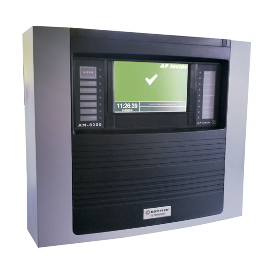
- Page 1 AM-8200 Programming Manual Firmware V.1.0 FIRE DETECTION PANEL...
- Page 2 INDEX General Description Definitions Front panel controls and signallings Front panel LED indications USER INTERFACE DESCRIPTION Functions and Access level Description of the keyboard operation to enter data in the programming folders Normal condition Pre-alarm condition Alarm condition Condition with fault zone events Condition with System fault events PROGRAMMING MENU Programming Menù...
- Page 3 Auto-learn Summary of HW Type-ID for modules Summary of SW Type-ID for modules CLIP ONLY SW-Type-ID for UDS units Groups Programming Menù Zone Programming Menù Configuration Menù Utility Menù System View Language Date and Time Parameters Local Special Drift warning function Mod.NONA Reability parameters Sounder...
- Page 4 DISABLE MENÙ Modify Detectors Modules Zones System Disable TEST MENU APPENDIX “A” – CONTROL BY EVENT EQUATION Appendix B : Software Type_ID for MODULES AM-8200 Programming Manual INDEX AM-8200_manu-prog Doc. M-162.1-AM8200-ITA Rev A.2 NOTIFIER ITALIA...
- Page 5 Do not try to use the control unit and devices connected without reading this manual DETECTION SYSTEM LIMITS An alarm or fire detection system can be very useful for the prompt warning of any dangerous event such as fire. In some cases it can automatically manage events (transmission of messages for room evacuation, automatic fire-extinguishing, TVCC system interface, access route or door blockage, automatic warning to authorities, etc.), but in any case, it does not ensure protection against damages to propriety).
- Page 6 AM-8200 CAN-BUS CAN-BUS Max 500 m CAN-BUS CAN-BUS Max 500 m Max 500 m AM-8200 PRINTER AM-8200-BB LCD-8200 DEFINITIONS LINE: Physical wiring where sensors, addressable manual Call Points, Sirens, addressable input and output modules are connected. POINTS: they are the addressable sensors and modules that can be connected to Lines. Hardware Address: the device Physical address (Start address for multi-module devices) on loop.
- Page 7 Example 2: A CMX-10RME (10 OUTPUT) card with address 10 will be programmed. SUB-address in Panel CMX-10RME – Hardware Address = 10 1 ª Output SUB-ADDRESS 1 10.1 2 ª Output SUB-ADDRESS 2 10.2 3 ª Output SUB-ADDRESS 3 10.3 4 ª Output SUB-ADDRESS 4 10.4 5 ª...
- Page 8 : Command for activating the Siren output and all output modules programmed with Type SW = SND in the EVACUATION absence of alarms and faults. To do this you need to know the level 2 password. DELAY RESET: This button is active only in case of alarm if the immediate activation of the Sounder outputs in the exclusions menu has been excluded.
- Page 9 FRONT PANEL LED INDICATIONS ALARM (Red): It flashes if there is at least one device in alarm and it has not been recognized yet. It is permanently lit if all alarm events have been recognized. REMOTE ALARM (Red): it is permanently lit if the output towards the fire alarm transmission devices (telephone dial) has been activated.
- Page 10 Functions and Access level Functions EN.54 Level Factory default password Alarm and Faults display Level 1 none Alarm and Faults recognition Level 1 none Delay Re-set (appropriate button) Level 1 none Excluded Zones/Points display Level 1 none Exclusions menu Level 2 22222 Test Menu...
- Page 11 Normal condition The following screen is displayed when the control panel is in Normal Condition If you touch the screen the following screen is displayed Function associated with PGRM key input of the program menu. Refer to Programming Menu Function associated with DISABLE key input of the disable menu.
- Page 12 Pre-alarm condition The following screen appears when the control panel is in the zone pre-alarm condition First zone in pre-alarm • time, date, progressive event • programmed text for the zone Any subsequent zones in pre-alarm Zone Counter in Pre-Alarm Use the arrow keys to scroll through the list of pre-alarm zones.
- Page 13 Alarm Condition The following display appears when the control unit is in condition of zone alarm. FIRST ZONE IN ALARM Date and Time + Event Number ID Text for the Zone If more zones are in Alarm : 2 ZONES IN ALARM LAST ZONE IN ALARM ...
- Page 14 Condition with Fault zone events The following display appears when the control panel is in condition of zone faults. Fault events are also initially displayed for zone Zone with Fault events Text programmed for this zone Counter for Faulty zones Through arrow keys ...
- Page 15 Condition with System fault events The Fault events relevant to the panel are defined as “System Faults” (ex. discharged battery, no mains, etc.). The system Faults are displayed with the maximum detail level. Date and Time of the Event Description of the System Fault Event...
- Page 16 RECOMMENDED SEQUENCE TO PERFORM THE PANEL PROGRAMMING The following operation sequence is recommended to perform the initial programming of the control unit, to prevent mistakes and consequent loss of time. The details of each operation are pointed out in the following pages. - Perform the wiring of the control unit lines and perform the appropriate tests as described in the installation manual before powering the control unit.
- Page 17 Programming menu By pressing the “PGRM” function key you can access the programming menu, to perform the configuration of the system or make changes to the programming. To access the Programming menu you must enter the Level 3A password (44444 is the default password) To enter the password, use the keyboard that appears on the screen and press ENTER.
- Page 18 Programming – System - System TYPE This function allows the choice of system Network type as follows: STANDALONE = Single Panel without Network connection with up to 8 lines NET 16 = Network of Panels with up to 16 lines in total NET 128 = Network of Panels with up to 128 lines in total ...
- Page 19 Through the arrow keys select the line style (OPEN - LOOP) Press the enter key to confirm the programming. LINE STYLE: Open = Open Line, Closed = Closed Line Protocol: ADV, CLIP: Configure the type of devices to handle. ADV = Line managed with ADV protocol, By selecting ADV the line can also handle up to 30 CLIP devices.
- Page 20 Through the arrow keys select the item which is required to be changed (“Check “ or “Check Enabl.”) through pressure of the enter key the editing function is activated. Through the arrow keys data are entered and through the enter key entered data are confirmed.
- Page 21 This function allows to change the Password for the three access levels. Each password consists of 5 numerical characters. Through the arrow keys select the item which is required to be changed. Press the enter key to activate the Numeric Keyboard to program the Password. Type the NEW password and hit Enter Re-type and confirm the password entered.
- Page 22 To enter the system name press the enter key and use the alphanumerical keyboard to enter the text. At the end press the Enter key to store the text. Programming - Points From the Programming menu by selecting the “Points” item is displayed the following screen, where you can manually configure each type of addressable device on field ( Detectors or Modules ).
- Page 23 Valid Types for ADVANCED Protocol Detectors HW TYPE_ID DEVICE TYPE NFX(I)-OPT Photo Smoke det. NFXI-OPT NFX(I)-TFIX58 Thermal det. NFXI-TFIX58 NFX(I)-TFIX78 Thermal det. NFXI-TFIX78 NFX(I)-TDIFF Thermal Rate of Rise det. NFXI-TDIFF NFX(I)-SMT2 Combined detector NFXI-SMT2 NFX(I)-SMT3 Combined detector NFXI-SMT3 IRX-751CTEM Combined detector IRX-751CTEM-W SMART4 NFX(I)-BEAM Addressable Beam NFXI-BEAM NFX(I)-BEAM-T...
- Page 24 To change the “CBE” field in this folder select the parameter through the arrow keys , press the enter key CBE for this point: If a CBE is already programmed it’s displayed here, other ways the field is empty as show. Use the alphanumerical keyboard to enter the data at the end, press the ENTER key on the keyboard screen to confirm.
- Page 25 - Control unit siren output - Alarm point indication on the display The reset procedure must be performed to clear all signaling. Led-Blink: By selecting “NO” in the” Led Blink” function, the flashing of the led on the sensor is disabled during the line interrogation. This function can be used in some environments such as hospitals, hotels, etc.
- Page 26 Perform the “Paste From …to” control for the programming of block points as indicated: Paste From ..to enter the start address through the FROM : xx arrow keys or by using the keyboard press the enter key confirm the datum enter the ending address through Paste From ..to the arrow keys ...
- Page 27 Example of programming of a CLIP sensor with HW-Type-Id “PINN” PINNACLE 7251 First TAB (Progr. of Type ID and Text associated with the sensor) HW Type_ID Programmable text max. 32 Char. Second TAB Third TAB (Progr. of Check, Al. Level, Daytime/night, Tracking and Led Blink ) Sensibility Value Corresponding...
- Page 28 Example of programming of NFXI-SMT2 First TAB (Progr. of HW-Type ID and Text associated with the sensor) Second TAB Tird TAB (Progr. of Check, Al. Level, Daytime/night, Tracking and Led Blink ) Corresponding Percentage of Obscuration ALARM LEVEL inside the Sensor Chamber ALARM 1 1% ft ALARM 2 - COMP.AUT.
- Page 29 Example of programming of NFXI-SMT3 First TAB (Progr. of HW-Type ID and Text associated with the sensor) Second TAB Tird TAB (Progr. of Check, Al. Level, Daytime/night, Tracking and Led Blink ) Alarm level Percentage of Obscuration inside the Sensor Chamber LIV.
- Page 30 Example of programming of IRX-751CTEM-W (SMART 4) First TAB (Progr. of HW-Type ID and Text associated with the sensor) Second TAB Tird TAB (Progr. of Check, Al. Level, Daytime/night, Tracking and Led Blink ) Alarm level Percentage of Obscuration inside the Sensor Chamber LIV.
- Page 31 TAB (Progr. of HW-Type ID and Text associated with the sensor) TAB (Progr. of Check, Al. Level, Daytime/night, Tracking and Led Blink ) Sensitivity (STD, LOW, HI) Display Value Percentage of Obscuration NFXI BEAM 25% m 30% m 40% m 50% m Variable from 30% m to 50% m (default for Sens-STD)
- Page 32 MODULES By selecting the “Modules” item and confirming the selection through the enter key you enter the programming procedure. This procedure is made up of 4 programming folders (to access the folders use the arrow keys ) The display shows by default the first device of the first line. Use the function keys to select another device.
- Page 33 For a description of “How-to” operate and the description of Tracking and Led-Blink field, please refer to Sensor programming screen before detailed. TAB : EDIT For the instructions “how-to” operate refer to “POINT Programming procedure” as this part is the same for Modules.
- Page 34 Led on device enabled to blink Enable manual silence Enable self - silence FAAST FL2011El - It has a single channel available with a smoke laser detector FL2012El - It has a single channel available with two smoke detectors in a common room for combined detection.
- Page 35 Programming TAB for FL2012EI Associated zone number CBE Equation Addresses of the first and second laser sensors (Pinnacle) installed inside the suction detection unit. Sensor Correlation. The user can choose whether the suction unit will activate its alarm signal in case of AND or OR by the 2 Pinnacle sensors installed.
- Page 36 NRXI-GATE ( Gateway for wireless System). Tabs Main Program HW Type SW Type Programmable Text max. 32 char. Zone associated to this Module Options Tab does not contain any entries programming. PAGE - 32 Programming Manual AM_8200 NOTIFIER ITALIA Doc. M-162.1-AM8200-ENG Rev A2 AM8200_manu-prog-ENG...
- Page 37 Auto-learn (automatic detection of installed devices) From the Points menu, by selecting the “Auto-Learn” item and confirming the selection through the enter key you enter the self-programming procedure of the devices installed on the line. Verify Double Address: YES By selecting YES, panel will check for more than one device programmed with same address in a line.
- Page 38 At the end of the Auto-programming procedure a summary of the devices found on the line is displayed Where: TYPE = Type of devices found ( see table above) ew device found NEW = N NFO = Devices previously programmed but not coherent with what was detected during the Auto-Learn procedure = total of devices detected on the line ( NEW + NFO + correctly programmed devices.) MIS = Devices previously programmed but not detected during the Auto-Learn The SAVE control saves the devices detected during the Self-Learn according to the following mode:...
- Page 39 Summary of HW Type-ID for Modules ( displayed after an Auto-Program ) HW Type_ID Description WMSS WM Sounder + Flash WMSB WM Flash WM Sounder DBSS Base with Sounder + Flash Base with Sounder WCP5A Outdoor Call Point MCP5A Indoor Call Point UDS-3N (CLIP only) ALW1 PSU ALW1...
- Page 40 Summary of SW Type-ID for modules INPUT MODULES CONNECTION TYPE SW Type_ID TYPE OF DEVICE MON3 Input module Input module used for N.O. contacts (Connection in conformity with EN54 rule). Input module used for N.O. contacts or any device Not compliant to EN 54 MMX-2 input module (obsolete module) Input module used for 4- wire conventional smoke detectors SCON...
- Page 41 INPUT MODULES FOR GENERAL SERVICES CONNECTION TYPE SW Type_ID TYPE OF DEVICE Input Module used as a Tamper signaling. Through an alarm input it MTRB signals a breakdown MACK Input module used to perform remote ACK (pulse) MTAC Input module used to perform remote SILENCING (pulse) MRES Input module used to perform remote RESET (pulse) OUTPUT MODULES...
- Page 42 OUTPUT MODULES FOR GENERAL SERVICES SOFTWARE CONNECTION MODE DESCRIPTION TYPE_id PWRC FORC Output module used to temporarily interrupt power supply, during SYSTEM RESET, for the 4- wire conventional smoke sensors, powered by a remote power supply. N.B.: this type SHALL NOT be programmed for the SILENCING GPND FORC output module activated at each alarm or Fault It is reset by ACK.
- Page 43 For UDS panels, two specific SW types are available, UDS1 and UDS2. UDS units are reminded that they can be installed starting from the beginning of the decade, excluding the decade from 0 to 9; occupy from a minimum of 2 up to a maximum of 6 addresses. The basic installation, compatible with UDS-1N (now obsolete) units, occupy the first two addresses to which the SW Type UDS1 is assigned;...
- Page 44 GROUPS Programming menu A group is a set of software devices that can perform associations. When a sensor or a module (which belong to the group) are in alarm, the group activates. If an output module is a member of the same group, it will be activated. This procedure is composed of 3 programming folders where to enter data is applied the editing function previously described in the paragraph: description of the keyboard operation to enter data paragraph The AM-8200 control unit has 400 groups, which can be programmed as:...
- Page 45 CBE equation Use the alphanumerical keyboard to enter the data at the end, press the ENTER key on the keyboard screen to confirm. CROSS ALARM The parameter ”Cross Alarm.” is valid if the group is associated in a CBE with the “XGRP” operator. NO = the group is active only when a thermal sensor ( a detector with HW-type-id “THER”) and an optical sensor ( a detector with HW-type-id “PHOT”...
- Page 46 G301 = TIM ( 18.00 08.30) Example: CBE of the high sensitivity group G302 = TIM ( 08.30 18.00) CBE of the low sensitivity group For the Zones to which this function is to be coupled the parameter “Daytime/Night = YES ”(refer to Zone programming) must be programmed.
- Page 47 Setting “YES” this Zone will use the programmed HI-LOW sensitivity Groups ( refer to HIGH AND LOW SENSITIVITY GROUPS above) to switch to LOW sensitivity during DAY and to HIGH sensitivity during the Night . Prealarm enable: YES/NO. This feature enables viewing and managing pre-alarm for sensors assigned to the zone Alarm Correlation - Indicates the number of alarm devices assigned to the zone to activate the siren outputs associated with this zone.
- Page 48 Programming - CONFIGURATION menu This function allows the configuration of the panel units connected to the Can-Bus Network. To modify the programmings, press the enter key use the arrow keys to change the parameter; at the end press the enter key to confirm.
- Page 49 This function allows to set the LCD-8200 model in the control unit. This feature allows you to enter a programmable TEXT of max.32 characters, which is displayed on the LCD-8200 as the example Press key – LCD or + LCD to program the previous/next LCD terminal ...
- Page 50 Programming – Delete Programmings This function will restore all Default programming ( NO NETWORK ): By pressing the Enter key all system data in the non-volatile memory of the control panel will be erased By selecting UTIL from the display of the system state screen you can access the Utility menu, which includes some functions generally used by servicing personnel To access the menu, enter the Level 3 Password (33333 is the default password).
- Page 51 UTILITY –System View: displays the system cpu configuration. UTILITY - Language: Is possible to select between languages UTILITY Date and Time This function allows to program the time and date of the control unit. To change values in “Date and Time” programming Form use the arrows to select the field to be changed (the characters of the selected field are white on dark background).
- Page 52 Use the arrows to select the press the enter key Hours form To change values in “Hours” programming Form use the arrows to select the field to be changed (the characters of the selected field are white on dark background). Use the arrow keys ...
- Page 53 This signalling can be used as a warning to perform a cleaning of the sensor optical chamber. This function is a general enable parameter valid for all the control unit points. The DRIFT WARNING function does not replace the maintenance request signalling, which in any case is always enabled. It is signalled when a sensor detects, for more than 36 consecutive hours, a value higher than 80 % of the alarm threshold.
- Page 54 This TAB is dedicated to the programming of the siren outputs (all devices programmed with SW SND type). The user can program the following items • Active sirens on correlation In case of alarm if this function is enabled, the sirens associated with this zone will be activated only when the programmed correlation number for the alarm zone is...
- Page 55 The historical archive has a capacity of 1000 events for a 2 loop station, up to 8000 events for a 16 loop central (1000 events for each LIB-8200). When the maximum number of memorized events is reached, the panel in case of a new event clears the most old event and stores the new event.
- Page 56 Press the enter key to perform the cancellation of all events stored in the historical event. History Log Disable: Through the “Disable” control (when activated) all new events arriving from both the detection lines and the keyboard are not stored in the historical file. In case of History Log was disabled , a System Fault is signalled in the Faults List To change this parameter in this folder press the enter key...
- Page 57 This function allows to examine the state of a point and in case of a detector, the analogue value can be displayed. This value will be displayed as a percentage with respect to the alarm threshold programmed for that device. Parameters relevant to modules, zones or software groups programmed can also be displayed.
- Page 58 The display shows by default the first device of the first line. To select another device use the function keys Module Status depends on Module Type (Input or Output) Modify the Output Status of a Control Module After selecting the “On/Off” field using the arrow keys ...
- Page 59 Display example of NRXI-GATE devices (Gateway for wireless system) The display shows by default the first Group. To select another Group use the function keys The display shows by default the first Zone. To select another Zone use the function keys AM_8200 Programming Manual PAGE - 55...
- Page 60 – – Through this function you can examine the active module lists which are connected to the control unit lines. Input modules Active input modules display. In the case of a line where there are no alarm input modules, the following indication is given: "No active input module"...
- Page 61 Firmware Update By pressing the DISABL function key in System State screen you can access the Disable menu, where detectors, modules, zones, etc. can be disabled The following menu is displayed By selecting the “Display” item the user enter the following menu where devices are displayed by the type: Counters of n°...
- Page 62 By selecting the “Modify” item, and typing the correct password Level 2, the following display will appear, where it is possible to change the state of Enabled/Disabled for the various devices Modify Status - Detectors The display shows by default the first device of the first line. To select another device use the function keys. When a detector is Disabled the control unit is inhibited to the reception of the Alarm and Faults signaling from the sensor.
- Page 63 Modify Status - Zones The display shows by default the first zone. To select another zone use the function keys When a Zone is Disabled the control unit is inhibited to receive the Alarm and Fault signaling from all the points which belong to the Zone.
- Page 64 This function allows the exclusion of all the output modules programmed with TYPE ID “UDS1” ( UDS and UDS2-N extinguishing panels) and select through the arrow keys “YES” To change this parameter in this folder press the enter key or “NO”...
- Page 65 Zone TEST : This function allows to start the Walk-Test procedure for a selected zone. This procedure is composed of 2 folders where the editing function previously explained is applied to enter data. Enter the zone number for which the test function must be activated.
- Page 66 – – Control by event concept Currently is available one formula (direct or reverse depending on the type of point) for each point (sensor / module) of the system; Multiple modules devices have a formula for each sub-address. For example: •...
- Page 67 Which is equivalent to: 1 - IF BOTH group G1 and group G2 are active 2 - OR 3 – Group G3 is ACTIVE and both group G4 and group G5 are active. N.B.: the equation must be written without inserting spaces between the characters to be entered. Sensor remote led in CBE This is required to use a single LED repeater connected to a single sensor, but indicate a multiple sensors alarm for a common area (Hospitals, Military dormitory, etc)
- Page 68 Operators used in the control by event equation: is the operator which requires AT LEAST ONE operator to be ACTIVE. Example: the output module equation is: OR (G9 G15 G23) or the OR operator can be omitted by entering: (G9 G15 G23) If ANY of the three operands in this equation (G9 G15 G23) is in alarm;...
- Page 69 It is not allowed to write a CBE for an inverse group, if the operands contained inside the round brackets are some groups having an index higher than the group for which the CBE must be associated as in the following example: CBE not allowed G305 = (G306 G307) CBE allowed...
- Page 70 PRE(CxxLxxSxxx) N° Loop Panel Detector Address Address It is the operator that uses the pre-alarm state of a sensor. Example: The equation of an output module is: OR (PRE (C1L1S2) PRE (C2L1S10)) If either of the two sensors (L1S2 of the control panel 1 or L1S10 of the control panel 2) is in pre-alarm, the output module to which the CBE is associated is activated.
- Page 71 It is the operator that allows to set tone and volume for zone groups via the CBE of inverse groups. TONE (Zone Volume Range Tone) Where : Tone = sound type in range 1 ÷ 33 Volume = volume in range 1 ÷ 4 Range_di_Zone = list of zones to activate the pattern (tone and volume) in Zxxx format: Zyyy (example Z1: Z10 to indicate zones from zone 1 to zone 10) TAC(SYS)
- Page 72 If the DEL equation duration time is not specified, the equation will be active until the reset of the elements in the equation. The maximum value of the duration time is 10 minutes The maximum values of the delay time is 10 minutes. SDEL The “SEDEL”...
- Page 73 Examples of programming: OPTIONS The following example points out three ways to perform a simple programming, that is the output module activation as a response to an alarm on a detector (or any other alarm input device) OPTION A OPTION B OPTION C Fire detection device...
- Page 74 Appendix B : Software Type_ID for MODULES Input modules for CONTACTS CBE Y/N TABLE‐1 Input Module 3 Treshold EN54 Y MON3 Input Module 2 Treshold (NOT EN 54 compliant) Y MON Same as MON, but label “MANUAL Call Point”. Y PULL Input Module Non Alarm Y NONA Input Module same as NONA, signal both status variation Y STAT Input Module for N.C. contacts Y NCMN Input Module Tamper. N MTRB Input Module for remote ACK (pulse). N MACK Input Module for remote SILENCE (pulse). N MTAC Input Module for remote RESET (pulse). N MRES Input Module conventional zone ...
- Page 75 Output Module FORC (not supervised) activated for Power Failure N MAINF Same as MANIF, but with supervised Output N MAINFC Output Module FORC controllable only by external commands. N REM Same as REM but with supervised Output N REMC Output Module which follows the status of the panel Sounder N SND Output Module FORC activated when the associated zone is in fault N ZFLT come ZFLT but with controlled output in standard mode N ZFLTC Output Modules NOT Supervised Output Advanced CBE Y/N TABLE ‐2C Output Module relay with potential‐free contacts. Y FORC Output Module FORC interrupts momentarily the power supply N PWRC Output Module FORC activated at every alarm / fault. N GPND Output Module FORC activated at every alarm. N APND Output Module FORC activated at every alarm. N GAC Output Module FORC activated at every fault. N ...
- Page 76 Addressable Strobe which follows the status of the panel Sounder N STR Call Points Advanced CBE Y/N TABLE ‐3 Same as MON, but label “MANUAL Call Point”.”. Y PULL Input Module Non Alarm (no display but CBE activation) Y NONA Input Module to ACK – Silence Buzzer from an impulsive contact (KEY) N MACK Input Module to SILENCE from an impulsive contact (KEY) N MTAC Input Module to RESET from an impulsive contact (KEY) N MRES The call point not pressed generates a fault event N MTRB The call point not pressed generates an Alarm event Y NCMN Same as NONA, but report any change in status (ON‐OFF‐ON) Y STAT Sounder / Strobe Advanced CBE Y/N TABLE ‐4 GSND Addressable Sounder that can be Silenced Y Addressable Sounder that follows the status of the panel Sounder N SND Addressable Strobe that can be Silenced Y ...
- Page 77 E-mail: notifier@notifier.it A Honeywell company Every care has been taken in the preparation of this data sheet but no liability can be accepted for the use of the information therein. Design features may be changed or amended without prior notice.