Table of Contents
Advertisement
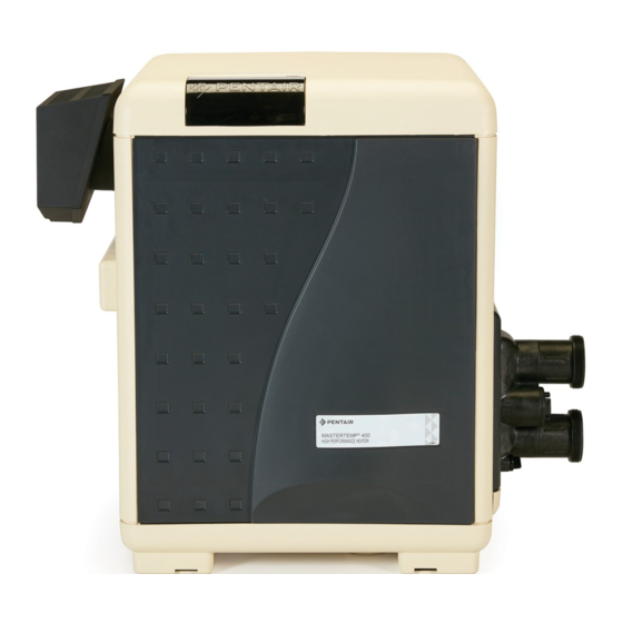
MASTERTEMP POOL AND SPA HEATER (AUSTRALIA)
(FOR OUTDOOR USE ONLY*) INSTALLATION AND USER'S GUIDE
240 VAC NATURAL GAS/LP GAS
MODELS
200HD (200 MJ/h)
300HD (300 MJ/h)
400HD (400 MJ/h)
FOR YOUR SAFETY – This product must be installed
and serviced by authorized personnel, qualified in
pool/spa heater installation. Improper installation and/
or operation can create carbon monoxide gas and
flue gases which can cause serious injury, property
damage,or death. As an additional measure of safety,
Pentair Water Australia Pty. Ltd. strongly recommends
installation of suitable Carbon Monoxide detectors in
the vicinity of this heater. Improper installation and/or
operation will void the warranty.
Notice: MasterTemp Heaters are designed for use with NATURAL
and PROPANE gas only.
ATTENTION INSTALLER: PLEASE GIVE THIS MANUAL
TO THE OWNER AND/OR OPERATOR ONCE INSTALLATION
IS COMPLETE.
FOR YOUR SAFETY - READ BEFORE OPERATING
•
IF YOU DO NOT FOLLOW THESE INSTRUCTIONS EXACTLY, A FIRE OR EXPLOSION MAY RESULT,
CAUSING PROPERTY DAMAGE, PERSONAL INJURY OR LOSS OF LIFE.
•
IMPROPER INSTALLATION, ADJUSTMENT, ALTERATION, SERVICE OR MAINTENANCE CAN
CAUSE PROPERTY DAMAGE, PERSONAL INJURY OR DEATH. INSTALLATION AND SERVICE
MUST BE PERFORMED BY A QUALIFIED INSTALLER, SERVICE AGENCY OR THE GAS SUPPLIER.
•
DO NOT PLACE ARTICLES ON OR AGAINST THIS APPLIANCE.
•
DO NOT USE OR STORE FLAMMABLE MATERIALS NEAR THIS APPLIANCE.
•
DO NOT SPRAY AEROSOLS IN THE VICINITY OF THIS APPLIANCE WHILE IT IS IN OPERATION.
•
DO NOT TRY TO LIGHT ANY APPLIANCE.
•
DO NOT TOUCH ANY ELECTRICAL SWITCH; DO NOT USE ANY PHONE IN YOUR BUILDING.
•
IMMEDIATELY CALL YOUR GAS SUPPLIER FROM A NEIGHBOR'S PHONE.
FOLLOW THE GAS SUPPLIER'S INSTRUCTIONS.
•
IF YOU CANNOT REACH YOUR GAS SUPPLIER, CALL THE FIRE DEPARTMENT.
For additional free copies of this manual; call AUS: 1300 137 344 - NZ: 0800 654 112.
Pentair Water Australia Pty. Ltd.s AU/NZ – Head Office
1-21 Monash Drive, Dandenong South, Victoria 3175 – Australia • 1300.137.344 • Fax 1800.006.668
1620 Hawkins Ave., Sanford, NC 27330, USA • (919) 566-8000 • (800) 831-7133
10951 W. Los Angeles Ave., Moorpark, CA 93021, USA • (805) 553-5000 • (800) 831-7133
Natural Propane
460946
460949
460945
460948
460944
460947
WHAT TO DO IF YOU SMELL GAS
www.pentairwater.com.au - www.pentair.com
(*) For heater indoor use, see page 22.
OWNER:
Retain For
Future
Reference
Advertisement
Table of Contents
Troubleshooting

Related Manuals for Pentair MASTERTEMP 200HD


Summary of Contents for Pentair MASTERTEMP 200HD
- Page 1 For additional free copies of this manual; call AUS: 1300 137 344 - NZ: 0800 654 112. Pentair Water Australia Pty. Ltd.s AU/NZ – Head Office 1-21 Monash Drive, Dandenong South, Victoria 3175 – Australia • 1300.137.344 • Fax 1800.006.668 1620 Hawkins Ave., Sanford, NC 27330, USA •...
-
Page 2: Product Hin / Code Requirements / Safety Warning
3) Construction : (HD = Heavy Duty Model) 4) Fuel Type : (LP = Propane gas or N = Natural gas) H. I. N. HEATER IDENTIFICATION NUMBER ID DESIGNATOR FOR PENTAIR POOL AND SPA MASTERTEMP HEATERS Example: = NATURAL GAS FUEL TYPE =... -
Page 3: Safety Warnings
If you need more information or if you have any questions regarding to this pool heater, please contact Pentair Water Australia Pty. Ltd. AU/NZ, AUS – at 1300 137 344 or + 61 3 9709 5800. WARRANTY INFORMATION The MasterTemp pool heater is sold with a limited factory warranty. -
Page 4: Code Requirements
Section 2. Introduction CODE REQUIREMENTS Installation must be in accordance with the following: DANGER CARBON MONOXIDE GAS IS DEADLY – Exhaust from this pool heater contains toxic levels of carbon monoxide, a dangerous, poisonous gas you cannot see or smell. DO NOT REMOVE Manufacturer’s Gas Installation Instructions •... -
Page 5: Consumer Information And Safety Information
Do not attempt to alter the rated input or type of gas by changing the orifice. If it is necessary to convert to a different type of gas, consult your Pentair dealer. Serious malfunction of the burner can occur which may result in loss of life. -
Page 6: General Specifications
SAFETY INFORMATION, (continued) WARNING — Risk of fire or explosion from flammable vapors. Do not store gasoline, cleaning fluids, varnishes, paints, or other volatile flammable liquids near heater. WARNING — Risk of explosion if unit is installed near propane gas storage. Propane (LP) gas is heavier than air. - Page 7 Customer Service If you have questions about ordering Pentair replacement parts, and pool products, please use the following contact information. Customer Service and Technical Support, AUS (9 AM - 5PM, Mon - Fri, Australia Wide) Phone: 1300 137 344 Fax: 1800 006 668...
-
Page 8: Table Of Contents
Contents Product HIN / Code Requirements / Safety Warning ....................2-10 Safety Warnings ........................Important Notices / Warranty Information ............................. Code Requirements ....................................Consumer Information and Safety Information ............................. General Specifications ..................................Section 1. Installation ......................Heater Description ....................................Sequence of Operation ..................................Putting the Heater into Service ................................ - Page 9 Contents Section 2. Operations (Start-Up / Before Start-Up) ....................Basic System Operation / START-UP OPERATION - HSI (Hot-Surface Ignition) Lighting/Operation ..........Operating Instructions ..................................To Turn Off Gas to Appliance ................................Safety Controls (Air Flow Switch / Water Pressure Switch / Hight Limits / Operation of Ignitiion Module) ........... 42 - 43 Control Panel / Menu Navigation / Operating the Heater ........................
-
Page 10: Section 1. Installation
THIS PRODUCT MUST BE INSTALLED AND SERVICED BY A PROFESSIONAL SERVICE TECHNICIAN, QUALIFIED IN POOL HEATER INSTALLATION. Pentair strongly recommends that all vents, pipes and exhaust systems be initially and periodically tested for proper operation. This testing can be accomplished by using a hand-held carbon monoxide meter and/or by consulting with a gas professional. -
Page 11: Specifications
Section 1. Installation SPECIFICATIONS These installation instructions are designed for use by qualified personnel only, trained especially for installation of this type of heating equipment and related components. Some states require installation and repair by licensed personnel. If this applies in your state, be sure your contractor bears the appropriate license. See Figure 2 for Outdoor Installations. DIMENSIONS IN CENTIMETERS &... -
Page 12: Plumbing Connections
The MasterTemp heater has the unique capability of direct PVC plumbing connections. A set of bulkhead fittings is included with the MasterTemp to insure conformity with Pentair’s recommended PVC plumbing procedure. Other plumbing connections can be used. See Figure 3 for plumbing connections. -
Page 13: Automatic By-Pass
Section 1. Installation AUTOMATIC BY-PASS Figure 5 shows a plumbing diagram for an automatic BY-PASS (IntelliValve). This in conjunction with an IntelliFlo VSF pump can provide added longevity of the heater and increased cost savings of operation. A 3-Port valve with an IntelliValve actuator is installed at the heater inlet. -
Page 14: Water Connections
Section 1. Installation WATER CONNECTIONS 3-Way Chlorinator The heater requires proper water flow and pressure for its Valve operation. See Figure 6 for the recommended installation. The filter pump discharges to the filter, the filter discharges Check Valve to the heater, and the heater discharges directly to the pool or spa. -
Page 15: Multiple Heater Installation
Section 1. Installation MULTIPLE HEATER INSTALLATION All plumbing on multiple heater installations must be done in parallel. See Figure 7 and Figure 8. To prevent heater overheating and to ensure heater longevity, water flow to each heater must be balanced for optimum operation. -
Page 16: Gas Connections
Section 1. Installation GAS CONNECTIONS FOR NEW HEATER INSTALLATION: SEE PAGE 17 TO INSTALL THE GAS PIPE ESCUTCHEON. THIS ENSURES THE HEATER IS RODENT RESISTANT. GAS LINE INSTALLATIONS The gas supply must be installed in accordance with the Gas Installation Code, AS/NZS 5601.1, as applicable and all applicable local codes. -
Page 17: Gas Pipe Escutcheon Installation
Section 1. Installation Gas Pipe Escutcheon Installation The gas pipe escutcheon ensures the heater is rodent resistant. The following describes how to install the round gas pipe escutcheon for a new heater installation. The gas pipe escutcheon should be installed when the gas pipe is being installed to the heater. -
Page 18: Testing Gas Leaks And Gas Pressure
Section 1. Installation TESTING GAS LEAKS AND GAS PRESSURE Before operating the heater, the heater and its gas connections must be leak tested. Do NOT use an open flame to test for leaks. Test all gas connections for leaks with soapy water. The gas valve must be completely disconnected from the gas supply piping system during any pressure testing of that system at test pressures in excess of 6.0 kPa (.87 psig). -
Page 19: Inlet Gas Pressure Requirements
Section 1. Installation INLET GAS PRESSURE REQUIREMENTS NOTE: The minimum value approved for input adjust- GAS PRESSURE MINIMUM MAXIMUM ment. Do not exceed the maximum supply pressure. All readings must be taken while heater is operating. NATURAL GAS 1.13 KPA 6.0 KPA Any adjustments or readings made while heater is off will result in performance problems. - Page 20 HEATER CLEARANCES – OUTDOOR IMPORTANT! • In an outdoor installation it is important to ensure water is diverted from overhanging eves with a proper gutter/drainage system. The heater must be set on a level foundation for proper drainage. • This unit shall not be operated outdoors at temperatures below -7 300 m or more The heater shall be located such that the heater’s flue terminal shall comply with the Australian standard.
-
Page 21: Outdoor Installation / Heater Clearances
CAUTION If installing the heater next to or near an air conditioning unit or a heat pump, allow a minimum of 1000 mm between the air conditioning unit and the heater. OUTDOOR INSTALLATION VENTING GUIDELINES 1500 mm 1500 mm SIDE VIEW 1500 mm Property Line 1500 mm... -
Page 22: Indoor Venting-General Requirements Heater Clearances / Indoor Installation . Outdoor Shelder
Section 1. Installation INDOOR VENTING — General Requirements NOTE: REMOVE OR COVER “OUTDOOR ONLY” LABEL LOCATED ON HEATER OUTSIDE PANEL WITH “INDOOR INSTALLATION” LABEL (P/N 474275) INCLUDED IN METAL FLUE COLLAR KITS (P/N SF 43-11-06 INDOOR INSTALLATION (SEE INSTALLATION GUIDE FOR CORRECT PLACEMENT OF THIS LABEL) P/N 474275 If you are considering connecting this heater to a pre-existing vent system, make sure that the vent system meets the appropriate venting requirements as given in this manual on pages 23-29. - Page 23 VENT INSTALLATION – INDOOR INSTALLATION OR OUTDOOR SHELTER Flueing must be in accordance with AS/NZS 5601.1 NOTE *: Vents extending 1.5 m (5 ft) or more Always vent the heater to the outdoors, see Note*. above the roof must be braced or guyed. Consult your local code officials for detailed information.
- Page 24 Section 1. Installation Table 5. – Maximum Number of Elbows per Vent Lengths (*) The maximum horizontal component of the flue Maximum Number of Elbows per Vent Lengths length is 1/3 of the total length. Maximum Elbows Total Vent Length Horizontal Maximum Vertical Vent Length Allowed...
- Page 25 3. Install the metal Flue Collar in the Vent Body of the heater (located under the outside vent cover). Listed Fasten the metal Flue Collar to the Vent Body with Termination two #10 sheet metal screws. Use high temperature 500 mm min. silicone RTV to seal the Flue Collar to the Vent Body.
- Page 26 Section 1. Installation HORIZONTAL VENTING The location of the flue terminal shall comply with the Australian standard. (See Figure 21): Chimney or Gas Vent Vent Cap and Riser Furnished a) At least 300mm below eaves, balconies and other by Installer projections.
-
Page 27: Horizontal Venting - Using Single-Wall Stainless Gas Vent
Section 1. Installation HORIZONTAL OR VERTICAL VENTING - USING SINGLE-WALL STAINLESS GAS VENT (See Figures 21, 22, 23 & 26) Vent the heater either horizontally or vertically using an optional vent adapter of the 150 mm (6 in) special gas approved stainless steel vent pipes. -
Page 28: Connecting Single-Wall Stainless Steel Vent To The Heater
Metallic: 1. Order an optional appliance adapter kit, (Pentair offers optional appliance adapter kits, call our Customer Service dept.) - Part No. 77707-0086 for Saf-T Vent or Saf-T Vent CI. - Part No. 77707-0087 for Z-Vent. 2. Remove the outside vent cover. -
Page 29: Horizontal Or Vertical Venting Flexible Duct (Flex-Vent)
Section 1. Installation Section 1. Installation 9. Vent Termination – Horizontal (Continued) Allow at least 1 M (3 ft) vertical clearance over vent Metal Special Support termination when terminating under an overhang or deck. Gas Vent weight requires Avoid corners or alcoves where snow or wind could have of pipe Appliance Listed... -
Page 30: Combustion Air Supply / Corrosive Vapors And Possible Causes
2580 sq. cm. 645 sq. cm. 645 sq. cm. Pentair does not recommend indoor installations that do not provide combustion Area indicated is for one of two openings; one at floor level and one at the ceiling. air from outside the building. -
Page 31: Direct Air Intake Duct With 3-Inch Pvc Pipe (Indoor Installation)
Direct Air Intake Duct with 80 mm PVC Pipe (Indoor Installation) For indoor heater installations where combustion air supply might be insufficient, the MasterTemp Heater is certified for a direct air intake duct using 80 mm PVC pipe. If outside air is drawn through 80 mm PVC duct directly into the heater, PVC pipe can be installed in accordance with the following requirements: The air intake opening MUST be installed at least 30 cm above the roof line or normal snow levels for free air flow. -
Page 32: Electrical Connections
Section 1. Installation ELECTRICAL CONNECTIONS Electrical Rating 50 Hz 240 Volts AC, single phase; 12 AMP inrush, 5 AMP steady state. The heater is supplied with a 240 VAC, 10 AMP, 50 Hz power cord (AS/NZS 3112) approved for outdoor use. The power cord wire is 3 x 16 AWG (3 x 10 mm ). -
Page 33: Heater Bonding
Section 1. Installation HEATER BONDING WARNING To reduce voltage gradients in the pool area, the ELECTRICAL HEATER BONDING heater and the pool system equipment must be CONNECTOR CONDUIT PORT electrically grounded and “bonded” together. Con- nect a solid copper conductor (8 AWG or larger) to the heater “bonding”... -
Page 34: Remote Control Connections (Fireman's Switch Connection)
Section 1. Installation REMOTE CONTROL CONNECTIONS 1. Switch off power to heater at main circuit breaker panel. 2. Unbolt and remove the access door panels. 3. Open control box cover (see Figure 31). 4a. To connect a 2-Wire Control (such as IntelliTouch or EasyTouch control systems) ™... -
Page 35: Connecting The Mastertemp Heater To The Intellicenter Control System Load Center Via Rs-485
Section 1. Installation Connecting the MasterTemp Heater to the IntelliCenter™ Control System ® Load Center via RS-485 For remote control and monitoring, the MasterTemp heater can be connected via the heater’s RS-485 COM port to the IntelliCenter Control System COM port. The heater can be wired to the IntelliCenter Control System via a RS-485 connection. - Page 36 Section 1. Installation Connecting the RS-485 Cable from the Heater to the Load Center To connect the MasterTemp heater to the load center: BEFORE REMOVING THE HIGH VOLTAGE COVER PANEL FROM THE LOAD CENTER OR POWER CENTER ENCLOSURE SWITCH OFF THE POWER AT THE HOUSE MAIN CIRCUIT BREAKER BOX.
- Page 37 Section 1. Installation Connecting the RS-485 Cable from the Heater to the Load Center (Continued) Note: COM PORT A& B 14 VDC, 2.0A Max. Combined +15 +DT -DT GND To heater COMMUNICATION PORTS A & B Control Panel 14 VDC, 2.0A Max. Combined. ®...
-
Page 38: Mastertemp Heater Wiring Diagram
Section 1. Installation MASTERTEMP WIRING DIAGRAM (3-WIRE SYSTEM) Figure 37. MasterTemp Pool and Spa Heater P/N 474131 Rev. M 8/2020... -
Page 39: Mastertemp Heater Electrical Schematic Ladder Diagram
Section 1. Installation MASTERTEMP ELECTRICAL SCHEMATIC LADDER DIAGRAM BYPASS VALVE 4.) EXTERNAL VALVE THAT NEEDS TO BE INSTALLED. Figure 38. P/N 474131 Rev. M 8/2020 MasterTemp Pool and Spa Heater... -
Page 40: Section 2. Operations (Start-Up / Before Start-Up)
Section 2. Operations Operations BASIC SYSTEM OPERATION Start pump, make sure the pump is running and is primed, to close the water pressure switch and supply power to heater. Be sure the pool and/or spa is properly filled with water. Follow the Lighting/Operating instructions below. MASTERTEMP HSI ELECTRONIC IGNITION LIGHTING/OPERATION FOR YOUR SAFETY: READ BEFORE LIGHTING WARNING... -
Page 41: Operating Instructions
Section 2. Operations OPERATING INSTRUCTIONS 1. STOP! Read the safety information on (page 40). Set both pool and spa thermostats to the lowest settings. External Manual Shut-off Valve Turn off all electric power to the appliance. This appliance does not have a pilot. It is equipped with an ignition device which automatically lights the burner. -
Page 42: Safety Controls (Air Flow Switch / Water Pressure Switch / Hight Limits / Operation Of Ignitiion Module)
Section 2. Operations SAFETY CONTROLS AIR FLOW SWITCH (AFS) The air flow switch, see Figure 40, is a safety device used to insure that the combustion air blower (fan) is operating and has been designed to monitor the vacuum (negative) pressure within the blower housing. The air flow switch is factory set and is connected upstream of the ignition module. - Page 43 Section 2. Operations SAFETY CONTROLS, (continued) OPERATION OF IGNITION MODULE , (see Figure 43), The Ignition Module is microprocessor based and operates on 24VAC supplied by the transformer. The control utilizes a microprocessor to continually and safely monitor, analyze, and control the proper operation of the gas flame holder.
-
Page 44: Control Panel / Menu Navigation / Operating The Heater
Section 2. Operations CONTROL PANEL Pool/Spa LCD Temperature Control Panel Description Toggle Button Display The LCD displays two lines of text. LCD Display: During normal heater operation the current pool or spa water temperature is shown on line 1 of the display. The heater set point for the pool or spa is shown on line 2 of the display. -
Page 45: Menu
Section 2. Operations Menu POOL MAX (65°F-104°F): The maximum heater operating temperature for the pool. SPA MAX (65°F-104°F): The maximum heater operating temperature for the spa. UNITS: Select F (Fahrenheit) or C (Celsius) to display change the display of the heat settings. Select US or Metric units. HISTORY: Use Up/Down button to scroll through the last five heater errors. -
Page 46: Section 3. Troubleshooting
Section 1. Troubleshooting Troubleshooting Initial Troubleshooting Only qualified, trained service technicians with appropriate test equipment should service the heater. Remember that all parts of the system affect heater operation. Before starting this troubleshooting procedure, make sure that the pump is running correctly, that there are no blockages in the system, that the valves are correctly set and that the time clock is correctly set and is running. -
Page 47: Initial Troubleshooting / Error And Fault Codes
Section 1. Troubleshooting Error and Fault Codes Table 10. Heater Error and Fault Codes Fault Condi�on Error Code Note Troubleshoo�ng Displayed Water pressure switch ERR PS If water flow is established the No water flow thru open the error is cleared and normal heater opera�on is resumed. -
Page 48: Troubleshooting Flow Charts
Section 3. Troubleshooting Troubleshooting Flow Charts Troubleshooting Instruction Initial Troubleshooting Only qualified, trained service technicians with appropriate test equipment should service the heater. Remember that all parts of the system affect heater operation. Before starting this troubleshooting procedure, make sure that the pump is running correctly, that there are no blockages in the system, that the valves are correctly set and that the time clock is correctly set and is running. -
Page 49: Heater Will Not Fire Troubleshooting (A, B)
Section 3. Troubleshooting Heater Will Not Fire - A Start Depress “POOL” or “SPA” ON Heater should fire on demand Is green “SPA” or button on Membrane Pad. for heat. “POOL” LED “on” Does “POOL” or “SPA” LED come on? Check that the 12-pin Check for line voltage to Restore power to heater. - Page 50 Section 3. Troubleshooting Heater Will Not Fire - B Start Is ERR PS displayed on LCD? Verify that pump is on, filter is not blocked, and the water flow is above the minimum requirement. Service pump/filter and elimi- nate other flow obstructions. With pump running, adjust Water Pressure Switch to lower pressure until ERR PS...
-
Page 51: Ign Is On Alarms: Ags, Afs, Hls, Ps, E01 Or 126 / Sfs
Section 3. Troubleshooting IGN is ON ALARMS: AGS, AFS, HLS, PS, E01 or 126 Gas flow during ignition and Verify connection to HSI igniter, burner fire for less than 7 seconds. HSI is not broken, flame current status. Gas flow during ignition try, but burner does not fire. - Page 52 Section 3. Troubleshooting Diagnostic Alarms: AGS, AFS, HLS, PS, E01 or 126 ERR AGS or Verify that water flow rate is Service pump and filter to above minimum required for restore proper flow. After ser- ERR HLS heater. vicing, verify proper operation Replace High Limit of Pressure Switch (PS).
- Page 53 Section 3. Troubleshooting Diagnostic Alarms: SFS ERR SFS Check Heat Exchanger Coil for leaks, liming, soot, or low flow. Heater starts and runs OK, but temperature of exhaust climbs to 450°–500° in 3–5 Check Thermal minutes. Regulator: Open at 120°? Replace Heater (HD ) Membrane Pad.
-
Page 54: Burner / Heat Exchanger Troubleshooting
Section 3. Troubleshooting Burner Troubleshooting SYMPTOM CAUSE REMEDY Loud, high-pitched whine Flame is too rich. Verify pressure tap between gas valve and blower inlet. See page 53 and verify that the gas regulator setting is –0.2" (–0.5cm) wc. Contact a qualified technician or service agency to replace the gas orifice. -
Page 55: Section 4. Maintenance
Section 4. Maintenance Maintenance Instructions CARE AND MAINTENANCE WARNING Risk of fire or explosion from flammable vapors. Do not store gasoline, cleaning fluids, varnishes, paints, or other volatile flammable liquids near heater or in the same room with heater. The following maintenance is recommended every six months and at the start of every swimming season: 1. -
Page 56: Liming The Heater - Pressure Relief Valve
Section 4. Maintenance DE-LIMING THE HEATER WARNING Working with muriatic acid can be dangerous. When cleaning elements always wear rubber gloves and eye protection. Add acid to water, do not add water to acid. Splashing or spilling acid can cause severe personal injury and/or property damage. -
Page 57: Water Pipe Escutcheon Installation
Section 4. Maintenance Water Pipe Escutcheon Installation Optional Pressure Relief Valve Escutchen: Note: If the heater is equipped with an optional Pressure Relief Valve, use the escutcheon on the Pressure Relief Valve water pipe. If required, before installing the escutcheon, carefully remove the round Pressure Relief Valve knock out from the heater panel. -
Page 58: After Start-Up
Section 4. Maintenance AFTER START-UP CHECKING WATER FLOW WARNING Fire or flooding hazard. If the unit overheats and the burner fails to shut off, follow instructions under “To Turn Off Gas to the Appliance”, page 41, and call a qualified service technician to repair unit. After start-up, the outlet water pipe should feel slightly warmer than the inlet pipe. -
Page 59: Maintaining Pool Temperature / Energy Saving Tips
CHEMICAL BALANCE POOL AND SPA WATER Your Pentair pool heater was designed specifically for your spa or pool and will give you many years of trouble-free service, provided you keep your water chemistry in proper condition. Water chemistry should follow good swimming pool water chemistry practices. When using a chlorinator, install it down stream from the heater and at a lower level than the heater outlet. -
Page 60: Chemical Balance
Section 4. Maintenance CHEMICAL BALANCE, (continued) It is wise to test pool water regularly. Never allow chlorine residual to drop below 0.6 ppm (parts per million). The minimum level for effective chlorine or bromine residual is 1.4 ppm. pH - The term pH refers to the acid/alkaline balance of water expressed on a numerical scale from 0 to 14. -
Page 61: Section 5. Replacement Parts
31/32 (Key Nos. 8 through 9), see Page 64. Repair Parts are available from a Pentair dealer. If your dealer cannot supply you, call Customer Support at 1-800-831-7133. P/N 474131 Rev. M 8/2020 MasterTemp Pool and Spa Heater... -
Page 62: Replacement Parts
Section 5. Replacement Parts MASTERTEMP REPLACEMENT PARTS CLAMP LID TUB DESIGN Lid Nut/Washer (9x) Combustion Chamber Gasket For heaters manufactured between 1/12/2009 and 10/31/2013 (clamp lid tub design) Note: Kits also include Clamp Assembly, O-Ring and Silicon Tube (see page 63) Rodent Resistant Parts List (see page 63) 29. - Page 63 Section 5. Replacement Parts MASTERTEMP REPLACEMENT PARTS REPAIR PARTS – BURNER SYSTEM Model Part 200NA 300NA 400NA Qty. Description 200LP 300LP 400LP Combination Gas Control Valve Kit 42001-0051S 42001-0051S 42001-0051S 3/4" Union 38404-4097S 38404-4097S 38404-4097S Gas Orifice Gas Orifice O-Ring •...
- Page 64 Section 5. Replacement Parts MASTERTEMP REPLACEMENT PARTS REPAIR PARTS – WATER SYSTEM Model Part 175NA - 200NA 300NA 400NA Description Qty. 175LP - 200LP 300LP 400LP Tube Sheet Coil Assembly Kit (NA, LP Series) (Includes Key No.3) 77707-0232 77707-0233 77707-0234 474058 474060 474061...
- Page 65 Section 5. Replacement Parts MASTERTEMP REPLACEMENT PARTS 14/15 REPAIR PARTS – ELECTRICAL SYSTEM Model Part 200NA 300NA 400NA Description Qty. 200LP 300LP 400LP Heater Display Cover 42002-0035 42002-0035 42002-0035 Igniter Bracket 42001-0030S 42001-0030S 42001-0030S Igniter/Igniter Gasket Kit Incl. Key Nos. 3 and 4) 77707-0054 77707-0054 77707-0054...
- Page 66 NOTES MasterTemp Pool and Spa Heater P/N 474131 Rev. M 8/2020...
- Page 67 NOTES P/N 474131 Rev. M 8/2020 MasterTemp Pool and Spa Heater...
- Page 68 Australia • 1300.137.344 • Fax 1800 006.668 www.pentair.com.au All indicated Pentair trademarks and logos are property of Pentair Inc. or its global affiliates in the U.S.A. and/or other countries. Third party registered and unregistered trademarks and logos are the property of their respective owners ©...