Table of Contents
Advertisement
Quick Links
Advertisement
Table of Contents

Related Manuals for Alienware Area-51 m5500


Summary of Contents for Alienware Area-51 m5500
- Page 1 i -1...
- Page 2 Notice The information in this user’s manual is subject to change without notice. THE MANUFACTURER OR RESELLER SHALL NOT BE LIABLE FOR ERRORS OR OMISSIONS CONTAINED IN THIS MANUAL AND SHALL NOT BE LIABLE FOR ANY CONSEQUENTIAL DAMAGES WHICH MAY RESULT FROM THE PERFORMANCE OR USE OF THIS MANUAL.
-
Page 3: Table Of Contents
TABLE OF CONTENTS PREFACE Symbols and Conventions Protecting Your Computer - Avoid Abusive Handling and Adverse Environment Chapter Summaries GETTING TO KNOW THE BASICS Performance Features (1-2,3) System at a Glance (1-4) Top View (1-4,5,6,7) Front and Rear Views (1-8,9) Side Views (1-10,11) Bottom View (1-12,13) AC Adapter (1-14) - Page 4 Modifying the BIOS Settings (2-4) Main Setup (2-4) Advance Setup (2-4,5) Security Setup (2-5,6) Power Setup (2-6,7) Boot Setup (2-7,8) Exit Setup (2-8) BATTERY POWER & POWER MANAGEMENT The Battery Pack (3-2) Lithium-Ion Battery Technology (3-2) Battery Low-Power Warning (3-3) Installing and Removing the Battery Pack (3-4,5) Charging the Battery and Charging Time (3-5) Checking the Battery Level (3-6)
- Page 5 Modem Problems (5-12) Network Adapter/Ethernet Problems (5-13) PC Card/PCMCIA Problems (5-14) Performance Problems (5-15) Firewire (IEEE1394) and USB2.0 Problems (5-16) APPENDIX A Product Specification APPENDIX B Agency Regulatory Notices i -5...
-
Page 6: Using This Manual
Preface Using This Manual This user’s manual contains general information about the hardware and software setup, troubleshooting, and technical specifications of the notebook computer. Symbols and Conventions The following conventions and symbols are used in this manual: When keys are to be pressed at the same time, a plus (+) symbol is used. - Page 7 Protecting Your Computer - Avoid Abusive Handling and Adverse Environment Following the advice below will help ensure that you get the most out of your investment. Your computer will serve you well if you take good care of it: Do not expose the computer to direct sunlight or place it near sources of heat.
- Page 8 The total ampere ratings of the equipment plugged in should not exceed the ampere rating of the cord if you are using an extension cord. The total current rating of all equipment plugged into a single wall outlet should not exceed the fuse rating. Do not connect another AC adapter to your notebook.
-
Page 9: Chapter Summaries
Chapter Summaries The following is a summary of the available chapters and appendices in this manual. Chapter 1: Getting to Know the Basics In this chapter, you will learn the basic operations and features of your computer. It gives you a general understanding of the components of your computer. -
Page 11: Getting To Know The Basics
chapter 1 getting to know the basics C H A P T E R O N E GETTING TO KNOW THE BASICS This chapter introduces the features and components of the computer. -
Page 12: Performance Features
chapter 1 getting to know the basics Performance Features High-Performance Processor with Alviso Chipset The notebook PC is equipped with a powerful Mobile Intel Pentium M or Celeron M processor. Together with the latest Alviso chipset and technologies, the system offers advanced PC performance. Unique Dual Graphic Boot Feature The system has two graphics engines built-in. - Page 13 chapter 1 getting to know the basics IEEE1394 for ultra high-speed connection to high-bandwidth digital video devices and USB2.0 ports to connect to any USB-based peripheral devices. Wireless LAN The internal wireless LAN module allows your notebook to connect wirelessly to other 802.11-enabled systems, devices, or networks. Internal USB Slot for Integrated USB Devices (Optional) The optional USB Bluetooth module or USB thumb drive gives you added function with the notebook.
-
Page 14: System At A Glance
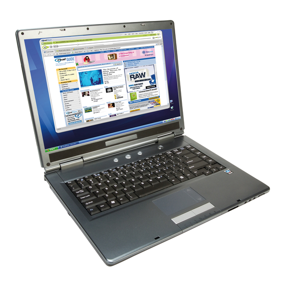
chapter 1 getting to know the basics System At A Glance LCD Latch The LCD latches lock / unlock the LCD panel. Built-in Microphone The built-in microphone records sound. LCD Display This panel is where the system content is displayed. The LCD panel has a maximum opening of 135 degrees. - Page 15 chapter 1 getting to know the basics Built-in Stereo Speakers The built-in speakers output the sound in stereo. Keyboard The keyboard is used to enter data. It has an embedded numeric keypad and cursor control keys. (See Keyboard Section for details.) Touchpad The touchpad is a built-in pointing device with functions similar to...
- Page 16 chapter 1 getting to know the basics Settings > Control Panel > Power Options > Advanced] menu. Press the power / suspend button again to return from the suspend mode. (See Chapter 3 for more details on system suspend function.) Note: When the system power is initially turned on, the Scroll-lock, Cap-lock, and Numeric keypad LED indicators will light up momentarily to indicate the...
-
Page 17: Front And Rear Views
chapter 1 getting to know the basics Front and Rear View Warning: Do not place any heavy objects on top of the notebook. This may damage the display. External VGA Port The 15-pin VGA analog port is for connecting the external CRT monitor or projector. -
Page 18: Side Views
chapter 1 getting to know the basics Stereo Headphone/SPDIF-out Jack The stereo headphone jack (3.5-mm diameter) is where you connect the headphones or external speakers. Alternatively, you may connect the SPDIF output to an external DTS, AC3, or PCM sound processor/decoder in your home stereo system. 8. - Page 19 chapter 1 getting to know the basics 2. Modem Port This is where you plug the phone jack (RJ-11) for fax/modem functions. 3. Optical Drive and Disk Eject Button and Manual Eject Key Hole If your computer comes with the combo drive, DVD-RW, DVD+RW, or DVD-Dual drive, you may save data onto a CD-R/CD-RW or DVD RW disc.
-
Page 20: Bottom View
chapter 1 getting to know the basics Bottom View Battery Pack and Battery Latch The battery pack is a built-in power source for the notebook. Slide the battery latch to release the battery pack. 1-10... - Page 21 chapter 1 getting to know the basics USB Device Cover (Optional) Underneath the cover, there is a USB connector. You may install the optional Bluetooth module or USB thumb drive into this slot. Hard Disk Drive Cover The system’s hard disk drive is located under the cover. The HDD can be upgraded to a larger capacity.
-
Page 22: Ac Adapter
chapter 1 getting to know the basics AC Adapter DC-out Connector The DC-out connector docks to the power jack (DC-in) on the computer. Adapter The adapter converts alternating current into constant DC voltage for the computer. AC Plug The AC plug plugs into the AC wall outlet. Warning: Make sure you are using a standard 3-prong AC wall socket with a ground pin. -
Page 23: Led Status Indicators
chapter 1 getting to know the basics LED Status Indicator The LED Status Indicator displays the operating status of your notebook. When a certain function is enabled, an LED will light up. The following section describes its indication. System & Power Status Indicators LED Graphic Symbol Note:... -
Page 24: Keyboard Features
chapter 1 getting to know the basics Keyboard Features Function Keys (Quick Keys) Graphic Symbol Action For various system controls, press the Fn (Function) key and the Fx key simultaneously. 1-14 System Control Fn + F1 Enters suspend mode. Fn + F3 Audio mute on or off. -
Page 25: Windows Keys
chapter 1 getting to know the basics Windows Keys Your keyboard also has two Windows keys: 1. Start Key This key allows you to pull up the Windows Start Menu at the bottom of the taskbar. 2. Application Menu Key This key brings up the popup menu for the application, similar to a click of the right mouse button. -
Page 26: Touchpad
chapter 1 getting to know the basics Touchpad The built-in touchpad, which is a PS/2-compatible pointing device, senses movement on its surface. As you move your fingertip on the surface of the pad, the cursor responds accordingly. The following items teach you how to use the touchpad: Move your finger across the touchpad to move the cursor. -
Page 27: Graphics Subsystem
chapter 1 getting to know the basics Graphic Subsystem Your computer uses a high performance 15-inch or 15.4-inch (wide) active matrix TFT panel with high resolution and multi-million colors for comfortable viewing. The system has two graphics engines built-in. A switch allows you to choose either the external MXM graphics engine or the integrated Intel GMA900 Extreme3 graphics engine. -
Page 28: Opening And Closing The Display Panel
chapter 1 getting to know the basics attached, change to suspend mode when not in use. Opening and Closing the Display Panel To open the display, push the LCD latch inwardly and lift up the lid. Then tilt it to a comfortable viewing position. The LCD panel has a maximum opening of 135 degrees. -
Page 29: Audio Subsystem
chapter 1 getting to know the basics Audio Subsystem Your computer’s audio subsystem is Sound Blaster Pro-compatible. Adjusting the Volume Manually To increase the volume, press Fn+ F5. To decrease the volume, press Fn+F6. Adjusting the Audio Volume in Windows Click the speaker symbol in the task tray in Windows. - Page 30 chapter 1 getting to know the basics Modem Your computer comes with a 56K V.92 internal fax/modem and a phone jack (RJ-11), which is located on the left side of your computer. Use a telephone cable to connect the computer to the telephone wall outlet. Connecting the Modem Plug one end of the phone line into the modem port located on the rear side of the computer.
- Page 31 chapter 1 getting to know the basics Your computer is equipped with a 10/100Base-TX or 10/100/1000Base-TX Fast Ethernet network adapter. Connect the active LAN cable to the RJ-45 LAN port located on the left side of the computer. This allows you to access and transmit data in the local area network.
-
Page 33: Bios Setup And Security Feature
chapter 2 bios setup and security feature C H A P T E R T W O BIOS SETUP AND SECURITY FEATURE In this chapter, you will learn how to enter the BIOS Setup Menu and manipulate various hardware control settings. You will also learn how to use the built-in security features. - Page 34 chapter 2 bios setup and security feature The Setup Utility is a hardware configuration program built into your computer’s BIOS (Basic Input/Output System). It runs and maintains a variety of hardware functions. It is menu-driven to allow you to easily configure and change the settings.
-
Page 35: Entering The Bios Setup Screen
chapter 2 bios setup and security feature Entering the BIOS Setup Screen First, turn on the power. When the BIOS performs the POST (Power-On Self Test), press the F2 key quickly to activate the AMI BIOS Setup Utility. Note: You may need to press the F2 key fairly quickly. Once the system begins to load Windows, you may have to retry by cycle-power on again. -
Page 36: Modifying The Bios Settings
chapter 2 bios setup and security feature Modifying the BIOS Settings The AMIBIOS setup main menu is divided into sub-menus. Each menu item is described in this section. Main Setup Under this menu, you may change the time/date and view basic processor and system memory information. -
Page 37: Security Setup
chapter 2 bios setup and security feature storage device. Item Selections / Sub-menu Touchpad Enabled Support Disabled LCD Auto Enable DIMM Disable Function BIOS Post Enable Beep Disable Sound Security Setup Boot Settings Configuration Item Selections / Sub-menu Change Supervisor Password Change User... -
Page 38: Power Setup
chapter 2 bios setup and security feature passwords, the Supervisor password must be set first. The passwords activate two different levels of protection: The system always asks for a password every time it is powered The system asks for a password only when you attempt to enter the BIOS utility. -
Page 39: Boot Setup
chapter 2 bios setup and security feature (such as Windows 3.1 or Windows 95 or NT4) or non-Windows operating systems. In Windows ME/98SE/2000/XP, the suspend mode and settings are determined by settings in the Power Options Properties (Start > Control Panel > Power Options). Boot Setup Boot Settings Configuration Item... -
Page 40: Exit Setup
chapter 2 bios setup and security feature Note: If you select Realtek Boot Agent, the system will attempt to boot from the network. Note: When the BIOS performs POST, you may also press the F12 Key to enable the Boot Device selection menu. You may choose CD/DVD, Hard Drive, or Realtek Boot Agent as the first storage device to boot from. -
Page 41: Battery Power & Power Management
chapter 3 battery power & power management C H A P T E R T H R E E BATTERY POWER & POWER MANAGEMENT In this chapter, you will learn the fundamentals of power management and how to use it to achieve longer battery life. -
Page 42: The Battery Pack
chapter 3 battery power & power management In this chapter, you will learn how to operate your notebook on battery power, how to handle and maintain the battery pack, and learn about the system’s power saving features. The TFT display, central processor, and hard disk drive are the major hardware subsystems that consume the most power. -
Page 43: Battery Low-Power Warning
chapter 3 battery power & power management Battery Low-Power Warning 1. Low Battery Warning A low battery condition occurs when battery power is reduced to 6%. The red battery status LED indicator will blink and the system will beep once every 16 seconds or so. 2. -
Page 44: Installing And Removing The Battery Pack
chapter 3 battery power & power management Installing and Removing the Battery Pack To Remove the Battery Pack: 1. Place the notebook bottom-side up on a flat and secure surface. 2. Push the latch and pull the battery’s hard case away from the notebook. -
Page 45: To Install The Battery Pack
chapter 3 battery power & power management To Install the Battery Pack: Place the notebook bottom-side up on a flat and secure surface. 2. Carefully insert the battery pack into the battery compartment of the notebook. Charging the Battery and Charging Time To charge the battery while the battery pack is in the notebook, plug the AC adapter into the notebook and an electrical outlet. -
Page 46: Checking The Battery Level
chapter 3 battery power & power management Checking the Battery Level You can check the remaining battery power in the Windows battery status indicator, which is located at the lower right-hand corner of the task bar. (If you do not see a battery or AC-in icon on the task tray, go to the Power Options Properties box and click on the Advanced tab. -
Page 47: Using Windows Power Options
chapter 3 battery power & power management Using Windows Power Options Windows Power Management provides basic power saving features. In the Windows Power Options Properties [Start > Settings > Control Panel > Power Options] dialogue box, you may enter time-out values for the display and hard disk drive. Windows Power Management saves power by turning off the hard drive after 1 minute of inactivity, for example. - Page 48 chapter 3 battery power & power management In this dialog box, you can manually set the LCD and hard drive’s time-out values in the Plugged-in column and in the Running on Batteries column. Lower time-out values will save more battery power. Note: Also consult the Windows user guide for more information on how to use Windows power management functions.
-
Page 49: Suspend Mode
chapter 3 battery power & power management Suspend Mode Standby Suspend The system automatically enters this mode after a period of inactivity, which is set in the Power Schemes dialog box. In Standby mode, hardware devices, such as the display panel and hard disk, are turned off to conserve energy. - Page 50 chapter 3 battery power & power management Note: Do not install or remove the memory module when the system is in the suspend mode. Note: The actual dialogue box may appear slightly different than the dialog box shown above. 3-10...
-
Page 51: Power Button Action
chapter 3 battery power & power management Power Button Action The notebook PC’s power button can be set to turn off the system or activate the suspend mode. Go to [Start > Settings > Control Panel > Power Options] and click on the Advanced tab. -
Page 52: Low Battery Warning
chapter 3 battery power & power management Low Battery Warning You can define when and how the system warns you of its low-battery condition. Go to the Alarms tab in the Power Options Properties box. If you wish to hear audible beeps, click on the Alarm Action button and put a check on Sound Alarm. -
Page 53: Power Manual Quick Access
chapter 3 battery power & power management Power Manu Quick Access Instead of making specific selections in the Power Options Properties box, you can quickly and easily specify which pre-set power saving function you desire by clicking on the battery icon at the lower right-hand corner of the task bar. (If you do not see a battery or AC-in icon, go to the Power Options Properties box and click on the Advanced tab. -
Page 55: Upgrading Your Computer
chapter 4 upgrading your computer C H A P T E R F O U R UPGRADING YOUR COMPUTER In this chapter, you will learn how to upgrade the DRAM and hard disk drive, as well as how to install the optional wireless LAN mini PCI. -
Page 56: Upgrading The Hard Disk Drive
chapter 4 upgrading your computer Upgrading the Hard Disk Drive Replacing the original drive with one of larger capacity can increase the hard drive capacity of your computer. Depending on the model, the computer may use a 9.5 mm (height), 2.5-inch Ultra ATA-type hard disk drive. - Page 57 chapter 4 upgrading your computer Upgrading the Hard Disk Drive To replace the hard disk drive, do the following: 1. Turn OFF the computer. Unhook the AC cord and all cables/devices attached to the notebook. Remove the battery. 2. Place your hand on a large metal object momentarily to discharge any static electricity.
- Page 58 chapter 4 upgrading your computer Locate and remove the 4 Screw B’s from the HDD module. Remove the upper and lower metal cases. 7. Re-attach the metal cases to the new hard drive and tighten the 4 Screw B’s. Note that the green PC board of the hard disk drive is facing up.
- Page 59 chapter 4 upgrading your computer When you boot up the PC, you may need to create a primary HDD partition, reformat the new drive, and re-install the O/S, drivers, and all necessary applications.
-
Page 60: Upgrading The System Memory
chapter 4 upgrading your computer Upgrading the System Memory Many applications will generally run faster when the computer’s dynamic memory capacity is increased. The computer provides two DDR memory sockets, which are located underneath the system device cover. You can increase the amount of memory by replacing the existing one with a dual inline memory module (commonly known as SO-DIMM) of a higher capacity. - Page 61 chapter 4 upgrading your computer Installing a Memory Module (DIMM) into the System To install the DIMM, do the following: 1. Power OFF the notebook. Unplug the AC cord and all cables/devices attached to the notebook. Remove the battery. 2. Place your hand on a large metal object momentarily to discharge any static electricity.
- Page 62 chapter 4 upgrading your computer 5. If you need to remove an old DIMM from the socket, press out on the latches located on both edges of the socket at the same time. The DIMM should pop up to an angle of 30 degrees (see diagram below).
- Page 63 chapter 4 upgrading your computer 7. Pivot the DIMM until the latches on both sides of the socket snap into place. Note: Notice the notch on the DIMM. The notches should fit nicely with the socket. 8. Put the system device cover back and tighten the 9 Screw C’s. Congratulations! You have just completed the memory upgrade.
- Page 64 chapter 4 upgrading your computer Note: Your computer has been tested with a wide range of DIMM on the market. However, not all memory modules are compatible. Check with your system vendor for a list of compatible DIMM for your computer. 4-10...
- Page 65 chapter 4 upgrading your computer Adding a Mini PCI-Type Wireless LAN Card (Optional Device) Your computer comes with a unique mini PCI card socket, which is located next to the DRAM socket and underneath the WLAN module cover. The socket allows the computer to add unique features such as wireless LAN (IEEE802.11x).
-
Page 66: Installing A Mini Pci Card To The System
chapter 4 upgrading your computer Installing a Mini PCI Card into the System To install a new mini PCI card, do the following: 1. Follow the steps in the earlier section, Installing a Memory Module (DIMM) into the System, to access the mini PCI socket. 2. - Page 67 chapter 4 upgrading your computer 3. Locate the 2 antenna cables with connectors. Snap the cable onto the golden connector on the mini PCI wireless LAN card. (Note: The connectors are fairly small, so this may take some maneuvering. You may want to connect the antenna cables before inserting the wireless card into the socket.
-
Page 69: Troubleshooting
chapter 5 troubleshooting C H A P T E R F I V E TROUBLESHOOTING In this chapter, you will learn how to solve common hardware and software problems. - Page 70 Your computer has been fully tested and complies with the system specifications before shipping. However, incorrect operations and/or mishandling may cause problems. This chapter provides a reference for identifying and correcting common hardware and software problems that you may encounter. When you encounter a problem, you should first try to go through the recommendations in this chapter.
- Page 71 chapter 5 troubleshooting cause the system to misbehave. If you are not sure of the changes you made, try to restore all the settings to factory defaults. Be sure all the device drivers are installed properly. For example, without the audio driver properly installed, the speakers and microphone will not work.
-
Page 72: Audio Problems
Audio Problems No audio output - Software volume control is turned down in Microsoft Sound System or is muted. Double-click the speaker icon on the lower right corner of the taskbar to see if the speaker has been muted or turned down all the way. Most audio problems are software-related. -
Page 73: Hard Disk Problems
Hard Disk Problems The hard disk drive does not work or is not recognizable - If you had just performed a hard disk upgrade, make sure that the hard drive connector is not loose and that the hard disk drive is also correctly seated. Remove it and reinsert it firmly, and then restart your PC. - Page 74 instructions on decreasing the cache size or on removing temporary Internet files. Empty the Recycle Bin to create more disk space. When you delete files, Windows saves them to the Recycle Bin. The hard disk takes longer to read a file - If you have been using the drive for a period, the files may be fragmented.
-
Page 75: Optical Drive Problems
Optical Drive Problems The optical drive does not work - Try rebooting the system. The disk is damaged or files are not readable. After you have inserted a CD-ROM disk, it may take a moment before you can access its content. The drive does not read any disks - The CD may not be properly seated in the tray. -
Page 76: Display Problems
Display Problems The display panel is blank when the system is turned on - Make sure the computer is not in the standby or hibernate suspend modes. The display is turned off to conserve energy in these modes. The screen is difficult to read - The display resolution should be set to at least 1024x768 for optimal viewing. -
Page 77: Keyboard And Mouse Problems
Keyboard and Mouse Problems The built-in touchpad performs erratically - Make sure there is no excess perspiration or humidity on your hand when using the touchpad. Keep the surface of the touchpad clean and dry. Do not rest your palm or wrist on the surface of the touchpad while typing or using the touchpad. -
Page 78: Cmos Battery Problem
CMOS Battery Problem A message “CMOS Checksum Failure” displays during the booting process or the time (clock) resets when booting - Try to reboot the system. If the message “CMOS Checksum Failure” appears during the booting procedure even after rebooting, it may indicate failure of the CMOS battery. -
Page 79: Memory Problems
Memory Problems The POST does not show an increased memory capacity when you have already installed additional memory - Certain brands of memory modules may not be compatible with your system. You should ask your tech support for a list of compatible DIMM. The memory module may not be installed properly. -
Page 80: Modem Problems
Modem Problems The built-in modem does not respond - Make sure the modem driver is loaded properly. Go to [Start > Settings > Control Panel > Phone and Modem Options] and go to the Modems tab. Make sure the SmartLink 56K voice modem or V.92 modem is listed. Otherwise, click the Add button to add the modem drive, which is located in the factory CD-ROM (or floppy diskette). - Page 81 Network Adapter / Ethernet Problems The Ethernet adapter does not work - Go to [Start > Settings > Control Panel > System > Hardware > Device Manager]. Double-click on Network Adapters and check if Realtek RTL8139/810x Family Fast Ethernet NIC (or Realtek RTL8169/8110 Family Gigabit NIC) appears as one of the adapters.
-
Page 82: Pc Card/Pcmcia Problems
PC Card/PCMCIA Problems PC cards do not function- Make sure you have properly installed the driver for the card. Consult the card’s manual or contact the vendor for troubleshooting. The PC card cannot be recognized - Windows NT 4.0 does not support PCMCIA (PC card) function. -
Page 83: Performance Problems
Performance Problems The computer becomes hot - In a 35 back case are expected to reach 50 degrees. Make sure the air vents are not blocked. If the fan does not seem to be working at a high temperature (50 degrees Celsius and up), contact the service center. -
Page 84: Firewire (Ieee1394) And Usb2.0 Problems
Firewire (IEEE1394) and USB2.0 Problems The USB device does not work - Windows NT 4.0 does not support USB protocols. Check the settings in the Windows Control Panel. Make sure you have installed the necessary device drivers. Contact the device vendor for additional support. The IEEE1394 port does not work - Go to [Start >... -
Page 85: Product Specification
appendix A product specification PRODUCT SPECIFICATION... -
Page 86: System Memory
Processor and Core Logic Processor 2 MB L2 cache or cache Intel Alviso 915GM + ICH6-M (FW82801FBM) chipset Core Logic with video, audio, modem, and USB2.0 controllers integrated 533 MHz (Pentium M)/400 (Celeron M) front side bus 400/533 MHz DDR1/DDR2 interface System Memory DDR1/DDR2 SDRAM 333/400/533MHz, PC2700 and Memory Type... -
Page 87: Wireless Lan
Audio Chipset Chipset Intel (ICH6M) integrated audio controller Audio Codec Realtek ALC880 Audio Codec Sound DirectSound 3D, EAX 1.0 & 2.0 compatible Sound Capabilities A3D, I3DL2 compatible Capabilities AC97 V2.3 compatible 7.1 multi-channel compatible (through S/PDIF) Supports Azalia standard 2 stereo speakers Modem Chipset Intel (ICH6M) integrated modem controller with MDC... - Page 88 LAN / Ethernet Chipset Chipset 10/100Base-TX network standards or PnP Function 10/100/1000Base-TX network standards PnP Function Flow Control Windows 2000/XP Plug and Play compatible Flow Control Speed Automatic Jam and auto-negotiation for flow control Speed Selection Auto Negotiation and Parallel detection for automatic Selection Other speed selection (IEEE 802.3u)
-
Page 89: Ports And Connectors
Keyboard 87-key or 86-key QWERTY keyboard with embedded numeric keypad and Windows keys, 19.05mm pitch Touch pad Built-in touchpad Chipset TI1410 (PC Card), Genesys GL817E (Card Reader) PC Card Single Slot TYPE II, hot insertion and removal supported 4-in-1 Card Multimedia Card (MMC), Secure Digital Card (SD), Reader Format Memory Stick (MS), and MS Pro Card... - Page 90 Primary Battery Pack Feature Low battery state with low battery warning beep SmartPower Power Management Smart Battery Compliant; low battery warning beep Auto-sensing AC-in 100~240V, DC-out 20V, 90W Adapter AC-Input / DC-Output PnP Function AMI PnP BIOS Self Test Power On Self Test Auto DRAM auto-detection, auto-sizing Detection...
- Page 91 appendix A product specification Physical Specification Dimension Weight DVD-ROM Drive, and 6-cell battery pack) Environmental Operating Temperature: 5 to 30 Limits Operating Humidity: 20 to 90 percent RH (5 to 35 Storage Temperature: -15 to 50 m5500 Series: 358 (W) x 272 (D) x 25.9~34.1 (H) m5500 Series: 7.2 lbs / 3.27Kg (with 15.4”LCD, C (41 to 86 C (-5 to 122...
-
Page 93: Agency Regulatory Notices
appendix B agency regulatory notices AGENCY REGULATORY NOTICES... - Page 94 RF exposure compliance. This transmitter must not be co-located or operating in conjunction with any other antenna or transmitter. "Alienware declare that the m5500 SERIES (with wireless card: Intel WM3B2200BG/ WM3B2915ABG) is limited in CH1~CH11 by specified firmware controlled in USA."...
- Page 95 appendix B agency regulatory notices Modifications The FCC requires the user to be notified that any changes or modifications made to this device that are not expressly approved by the manufacturer may void the user’s authority to operate the equipment. Connections to Peripheral Devices Connections to this device must be made with shielded cables with metallic RFI/EMI connector hoods to maintain compliance with FCC Rules and...
- Page 96 appendix B agency regulatory notices emissions from digital apparatus as set out in the radio interference regulations of the Canadian Department of Communications. Le present appareil numerique nemet pas de bruits radioelectriques depassant les limites applicables aux appareils numeriques de Classe B prescrites dans le reglement sur le brouillage radioelectrique edicte par le Ministere des Communications du Canada.
- Page 97 appendix B agency regulatory notices FIMKO (Finland) DEMKO (Denmark) NEMKO (Norway) SETI (Finland) EANSW (Australia) SEV (Switzerland) IMQ (Italy) UTE (France) CCC (China) PSB (Singapore) PSE (Japan) BSMI (Taiwan) B (Polish) VDE (Germany) SASO (Saudi Arabia) The flexible cord must be of a HAR (harmonized) type HO5VV-F 3-conductor cord with a minimum conductor size of 0.03 square inches.
- Page 98 appendix B agency regulatory notices Do not disassemble the pack. Do not dispose of the battery pack in fire or water. To avoid risk of fire, burns, or damage to your battery pack, do not allow a metal object to touch the battery contacts. Handle a damaged or leaking battery with extreme care.
- Page 99 appendix B agency regulatory notices CLASS 1 LASER PRODUCT APPAREIL A LASER DE CLASSE 1 LASERSCHUTZKLASSE 1 PRODUKT Warning! Do not attempt to disassemble the cabinet containing the laser. The laser beam used in this product is harmful to the eyes. The use of optical instruments, such as magnifying lenses, with this product increases the potential hazard to your eyes.
- Page 100 appendix B agency regulatory notices C AU TION! T his par t is h ot. B e C are ful. V OR SI CH T! Di e se Flach e wird se hr he iss. When you see this symbol, be careful as this spot may be very hot.