Table of Contents
Advertisement
Quick Links
Advertisement
Table of Contents

Related Manuals for Meyra 2.445


Summary of Contents for Meyra 2.445
- Page 1 OPERATING MANUAL MODEL 2.445 / 9.506 The Motivation.
-
Page 2: Table Of Contents
Use ....................... 10 High-frequency radiation ..................10 Safety informations ....................10 Overview ..................... 11 Model: 2.445 / 9.506 ...................11 Statutory regulations ................12 Legal requirements for Germany ..............12 Electronic wheelchairs up to 6 km/h ............12 Electronic wheelchairs more than 6 km/h ...........12 CE regulations .....................13... - Page 3 Driving .........................23 Safety informations ..................23 Brakes ........................24 Service brake ....................24 Parking brake ....................24 Braking the wheelchair ................24 Braking distance ....................24 Positioning the operating module ..............25 Function description ..................25 Horizontal adjustment ..................25 Vertical adjustment ..................25 Remove the operating module ..............26 Fitting of the operating module ..............26 Turning the operating module to the side ..........26 Loading and transportation ................27 Safety informations ..................27...
- Page 4 Back support .......................41 Standard back support .................41 Standard back support cover ...............41 Adjustable back .....................42 Adjusting the angle of the back support ............44 ERGOpor-back support element ..............45 Arm supports ......................46 Adjusting the height of the arm supports ..........46 Remove the arm support ................47 Height stopper (Memory effect) ..............47 Adapting the arm cushion to the seat depth ..........47 Adjustment of seat width ................48...
- Page 5 Electrically height-adjustable legrest ..............59 Height adjustment ..................59 Adjusting the height of the footplate ............59 Removing the electrically height adjustable leg supports ......60 Attaching the electrically height adjustable leg supports ......60 Support wheels ....................61 Lap belt .......................62 Strapping on the lap belt with lock ............63 Putting on the lap seatbelt with velcro fastener ........63 Adjustment of belt length ................63 Headrest ......................64...
- Page 6 Service ......................71 Tyres: ......................71 Cleaning and maintenance ................72 Upholstery and covers ..................72 Plastic parts ....................72 Finish ......................72 Desinfection ......................73 Reinstallment ......................73 Repairs .........................73 Customer Service ....................73 Spare parts ......................74 Disposal ......................74 Drive batteries ....................75 Sealed drive batteries ...................75 Charging the drive batteries ................75 Replacing the batteries .................75 Safety informations ..................75 Battery instructions for storage ..............76...
- Page 7 Technical data ..................... 92 Kilometric performance ..................92 Hill climbing ability ..................92 Fuses ........................93 Lighting .......................93 Tools ........................94 Tightening torque for screwed connections ............94 Model 2.445 / 9.506 ....................95 Meaning of the labels on the wheelchair ............99 Inspection certifi cate ..................100 Guarantee ....................102...
-
Page 8: Foreword
This manual is to help you get accus- FOREWORD tomed to the handling of the Elec- tronic wheelchair as well as to prevent We thank you for the confi dence you accidents. have placed in our company by choos- ☞ ing an electric wheelchair from this Note: series. -
Page 9: Acceptance
ACCEPTANCE SPECIFICATIONS All products are checked for faults The electronic wheelchair is an envi- in the factory and packed in special ronment-friendly electric vehicle. It boxes. was developed to extend the mobility of persons with health-related or age- ☞ Note: related restrictions. -
Page 10: Use
High-frequency radiation ☞ Mobile telephones should The electronic wheelchair, with at- switched off during the use of the tached leg supports and arm supports, electric vehicle. – A mobile tel- serves exclusively for the conveyance ephone also transmits in stand-by of one sitting person. -
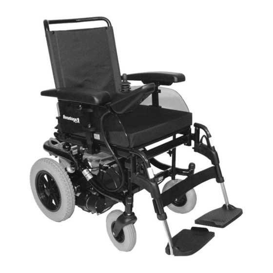
Page 11: Overview
OVERVIEW Model: 2.445 / 9.506 The overview shows the most important components and operating devices of the wheelchair. Pos. Description 1 Back support 2 Arm support 3 Seat cushion (option) 4 Leg support 5 Calf strap 6 Footplate 7 Selection lever drive-/push mode... -
Page 12: Statutory Regulations
Electronic wheelchairs up to 6 km/ STATUTORY REGULA- TIONS A liability insurance is only mandatory (in Germany) for an electronic wheel- Please comply with the legal require- chair with a speed in excess of 6 km/h ments of the country in which the but is nevertheless recommendable. -
Page 13: Ce Regulations
Contact your insurance offi ce fi rst. CE regulations There you will receive an insurance ☞ Note: licence plate (moped plate), which is This vehicle corresponds to the re- to be attached to the rear panel with spective demands of the EC-direc- two screws. -
Page 14: Handling The Electronic Wheelchair
Functional checks HANDLING THE ELEC- TRONIC WHEELCHAIR Before each ride the vehicle is to be checked for function and safety. Attention: ☞ For this observe chapter < Inspec- Observe the operating manual < tions before starting to drive > in Operating module >... -
Page 15: Tips For Accident Prevention
Tips for accident prevention First driving exercises A low maximum speed must be pre- If drive mode is switched off (brake selected on the control unit for the in- release lever in the < push > position) itial driving practice. Get accustomed the electronic wheelchair cannot be to the driving behaviour of the vehi- operated and braked via the joystick. -
Page 16: Driving In Street Traffi C
Driving in street traffi c The valid traffi c regulations must be observed and abided when participat- ing in public traffi c. ☞ Check the functioning of the light- ing system before each journey. ☞ Carry out a brief braking and steer- ing test at a –... -
Page 17: Decelerating/Stopping The Electronic Wheelchair
• Curves and slopes are to driven on Decelerating/stopping the elec- with adequate speed. tronic wheelchair • Danger of tilting while driving in Attention: curves or when turning around. Es- Braking the electronic wheelchair pecially on slopes and inclinations! when traveling downhill at high speed can cause it to skid. -
Page 18: Drive-/Push Mode
Drive-/push mode The lever (1) for switching the drive motors between the drive mode and push mode is located on the right side of the wheelchair. Attention: Push the wheelchair only for ma- noeuvring or in emergency cases but never on gradients. The electric magnetic brakes are switched off in the push mode. -
Page 19: Selecting The Push Mode
Selecting the push mode 1. Switch off the operating module because the pushing will otherwise be made diffi cult by the electric system. 2. Pull the locking sleeve (3) up and then push the selection lever to the rear ( 2). ☞... -
Page 20: Selecting The Operation
Selecting the operation Attention: The functions and safety of the electric wheelchair must be checked before the start of each journey. 1. Charge the drive batteries via the operating module before the fi rst journey. ☞ Observe the operating manual < operating module >. -
Page 21: Charging The Drive Batteries
Drive batteries should only be charged Charging the drive batteries with a battery charger that is suit- The drive batteries should be charged able for the type and rating of the immediately after daily use in order drive batteries. The guarantee is only to have the full driving distance avail- preserved to its full extent when the able on the next day. -
Page 22: Charging Procedure
Charging procedure The charging process for sealed drive batteries takes longer than that for open batteries with liquid electrolyte due to physical reasons. 1. Switch the operating module off. The selection lever should be in the drive mode position. 2. Insert the battery charger plug into the operating module (1). -
Page 23: Driving
Driving You determine the speed and the trav- el direction through the movement of the joystick (1) and the pre-selected maximum speed of your wheelchair. Attention: Drive especially carefully during your fi rst journey! Do this by setting the pre-selected speed to the lowest level. -
Page 24: Brakes
Brakes Braking the wheelchair The wheelchair stops when you let go Attention: of the joystick. Have the brakes repaired immedi- ately by a specialist dealer if they For allotted braking slowly guide the work one-sided or if the braking joystick back to the home position effect is reduced. -
Page 25: Positioning The Operating Module
Positioning the operating module Function description You will fi nd a detailed description of the keys and symbols in the operating manual for < Operating module >. The position of the operating module can be adjusted to suit the individual size of the user. -
Page 26: Remove The Operating Module
Remove the operating module To remove the control unit, slacken the clamping screw (1). Pull the oper- ating module to the front. ☞ Note: Carefully route the cable when do- ing this. Fitting of the operating module Insert the operating module into its clamping device. -
Page 27: Loading And Transportation
Loading and transportation Safety informations For the transport in vehicles, you must leave the wheelchair and sit in a suit- able seat in the vehicle. – The wheel- chair is not designed to withstand the forces which are generated in acci- dents, which exposes the user to con- siderable risks. -
Page 28: Transport Security
Transport security Carry out the following steps when the wheelchair is located in the trans- port vehicle: – Operate parking brakes. – Check the locking devices of de- tachable parts, or if necessary re- move them (e.g. side elements, arm supports) and store them safe- ly and protected. -
Page 29: Safety Informations
☞ Safety informations Note: ☞ ☞ Suitable fi xing points can usually Loose object are to be stored se- be found in the car and in the ve- curely. hicle operating manual. ☞ Before transporting the wheelchair, ask your car dealer how to secure it without risk to the existing fi... -
Page 30: Ramps And Lifting Equipment
Ramps and lifting equip- ment When the wheelchair is loaded with the help of ramps or lifting platforms, the following safety information are to be observed: ▲ The brochure < Safety information for electric vehicles >. ▲ The operating manual for the transport vehicle. -
Page 31: Special Safety Informations
▲ Special safety informations Only approved ramps or lifting platforms may be used. ▲ For safety reasons, the wheelchair Attention: must be unloaded (without bag- The loading capacity per ramp or gage and without user) during its lifting equipment must be for the loading into a car or when a split wheelchair: ramp is used. -
Page 32: Transport In Handicapped Transport Automobile
The power-knot-system is a fi rm, ret- Transport in handicapped rofi table element on the wheelchair, transport automobile on which the PRS and WRS merge. ☞ These requirements are fulfi lled by a Note: For transport in vehicles we rec- 4-point-system that consists of 2 front standardized latches for spanning re- ommend to leave the electronic... -
Page 33: Product Liability Instructions
☞ Safety informations Note: The headrest on the wheelchair ☞ When transporting a person, make serves as a support for the posture sure that there are no objects of the head, not as a transport se- jammed underneath the straps! curity. -
Page 34: Seat
Seat Adjusting the seat depth The seat depth can be changed by moving the back support to a differ- ent position. ☞ Note: The adjustment must be carried out by a workshop. For this the attachment screws (1) are to be removed on both sides. Then at- tach the back support holders again at the desired position with the secur- ing screws. -
Page 35: Ergopor Seat Element
ERGOpor seat element (Option) ERGOpor seat cushion The ERGOpor seat cushion is secured to the seat shell with Velcro fasteners and can be pulled off. ERGOpor seat element For cleaning- or maintenance work the ERGOpor seat unit can be removed. ☞... -
Page 36: Seat Inclination
Seat inclination The seat angle (1) can be adjusted through the telescopic rod in steps. ☞ See < Technical data >. Observe chapter < Adjusting the headlights >. Attention: Adjust the seat angle only when the wheelchair is standing on a level surface. -
Page 37: Mechanically Adjusting The Seat Angle
Mechanically adjusting the seat angle Before mechanically adjusting the seat angle lift the seat slightly. Screw the claming screw (2) on both sides far outward. Lift or lower the seat up to the marker, according to the desired seat inclination. Reinsert the clamping screw on both sides and tighten. -
Page 38: Electrically Adjusting The Seat Angle
Electrically adjusting the seat an- (Option) The seat angle can be adjusted electri- cally. The adjustment is carried out with the adjustment module. ☞ Note: Herefore view the operating man- ual < Operating module >. Attention: Adjust the seat angle only when the wheelchair is standing on a level surface. -
Page 39: Adjusting The Seat Height
Adjusting the seat height The seat frame receptacle (1) enables setting of two further seat heights. ☞ See < Technical data >. For this the screws (2+3) are to be dis- assembled. ☞ The self securing nuts are to be re- placed after several implementa- tions. -
Page 40: Suspension Of The Chassis
Suspension of the chassis For optimal sitting comfort the sus- pension (1) can be adjusted according to the desire of the user. Attention: Make sure that the adjustment ring sits securely before starting to drive. – Screw a loose adjustment ring tight enough, until the pressure of the spring prevents further loosen- ing. -
Page 41: Back Support
Back support Standard back support The standard back support (1) is step- lessly angle adjustable from about 0° to 30°. Standard back support cover The standard-back strap is spanned through the backrest tubes. The extended part of the back (2) is attached with velcro to the seat sur- face. -
Page 42: Adjustable Back
Adjustable back (Option) The adjustable back is adjustable through a velcro strap, the so called spanning straps (2). The cushion (1) is placed over it and attached with the velcro strap. Adjusting the adjustable back ☞ Note: ☞ The fi tting of the adjustable back (2) is best carried out with the user 4. - Page 43 Place the back cushion The back cushion (1) is to be folded over in the centre between the two horizontal seams 180° around the up- per spanning straps (2). – This creates a soft upper edge. ☞ Note: When the user leans against the front cushion again, pay attention that: ☞...
-
Page 44: Adjusting The Angle Of The Back Support
Adjusting the angle of the back support Mechanical back support adjust- ment – Loosen clamping screw (3). – Loosen counter nut (2) and screw it back. – Set the adjustment screw (1) ac- cording to the desired back sup- port angle. –... -
Page 45: Ergopor-Back Support Element
ERGOpor-back support element (Option) Remove the ERGOpor-back sup- port unit Loosen the attachment screws (1) and push the clamping tins inward. Then push the backrest element for- wards out of the backrest frame (2) and remove it. Attaching the ERGOpor back sup- port element Press the back support element, left and right, onto the back support... -
Page 46: Arm Supports
Arm supports The arm supports can be adjusted in height to suit the needs of the user. Attention: Do not use the arm supports to lift or carry the wheelchair. • Do not drive without the arm- rests! Adjusting the height of the arm supports Slacken the clamping screw (1), slide the end stop fully up and lightly tight-... -
Page 47: Remove The Arm Support
Remove the arm support Slacken the clamping screw (3) and pull off the arm support upwards. ☞ Note: The operating module must be re- moved fi rst if the arm support on the control side is to be detached. To remove the control unit, slacken the clamping screw (4). -
Page 48: Adjustment Of Seat Width
Adjustment of seat width The seat width can be adjusted by a lateral displacement of the arm sup- ports. Displace both arm supports by an equal distance after slackening the clamping screw (1) on both sides. ☞ Note: A reduction of the seat width to less than 43 cm is possible by switching the two arm supports. -
Page 49: Leg Supports
Leg supports Attention: Do not use the leg supports to lift or carry the wheelchair. • Lift the feet, respectively place them on the footplates before each movement of the wheelchair. • The operating module is to be switched off: –... -
Page 50: Folding Up The Footplates
Folding up the footplates The footplates are to be folded up for entering or exiting the wheelchair (1). Turning the leg supports to the side For easy transfer out of/into the wheelchair as well as driving closer to a closet, bed or bathtub the leg sup- ports can be swivelled away toward the in-/outside (2) + (3). -
Page 51: Remove The Leg Supports
Remove the leg supports For easy transfer into and out of the wheelchair as well as a reduced wheel- chair length (important for transport) the leg support can be removed (1). ☞ Note: Before swivelling the leg support loosen or remove the calf belt on one side. -
Page 52: Adjusting The Height Of The Footplate
Adjusting the height of the foot- plate Loosen the clamping screw (1) to ad- just the height. Telescope the foot plate to the desired height and then retighten the screw. ☞ Note: The maximum setting is marked by a guide slot (2). Angle adjustable footplates (Option) After loosening the clamping screw... -
Page 53: Continuous Leg Support
Continuous leg support The footboard of the continuous leg support (1) can be folded up to the side. Folding up the foot board For an unobstructed foot area, fold up the left side of the foot board to the right as far as it will go (2). Folding down the foot board Fold down the left side of the foot board until it rests on the foot board... -
Page 54: Angle Adjustment Of The Footboard
Angle adjustment of the foot- board – Switch the wheelchair off and shift the brake release lever into the drive position. – This prevents the wheelchair from rolling away acci- dentally. – Loosen the screwed connection (5) and adjust the footboard to the desired angle. -
Page 55: Depth Adjustment Of The Footboard
Depth adjustment of the foot- board The depth adjustment of the foot- board is done by repositioning the re- movable distancer pieces (6). – Light the footboard slightly on the left side. – Reposition the desired amount of distancer pieces on the left side. –... -
Page 56: Height-Adjustable Leg Supports
Height-adjustable leg sup- ports (Option) Removing the height adjustable leg supports For this pull back or press the locking lever (1). Afterwards swivel the leg support to the side and then pull it off in an up- ward direction. Attaching the height adjustable leg supports With the leg support in a swivelled- aside position, hang it in and then... -
Page 57: Adjusting The Height Of The Leg Supports
Adjusting the height of the leg supports When seated in the wheelchair, ask a carer to raise the leg support to the desired level. The length adjustment is given through the turning point at the height of the knee joint. 1. -
Page 58: Depth Adjustment Of The Calf Plate
Depth adjustment of the calf plate The calf plate (1) can be swivelled to the side and adjusted in three posi- tions in depth by repositioning the screws (2). -
Page 59: Electrically Height-Adjustable Legrest
Electrically height-adjust- able legrest The electrically adjustable leg support has an automatic length alignment and automatic electrical contact upon being mounted. Attention: Do not reach into the adjustment mechanism. – Danger of crushing! Height adjustment For the height adjustment of the leg supports view the users manual <... -
Page 60: Removing The Electrically Height Adjustable Leg Supports
Removing the electrically height adjustable leg supports Pull or press the locking lever back- ward (2). Afterwards swivel the leg support to the side and then pull it off in an up- ward direction. Attention: With the electrically adjustable leg support removed the electric contact (3) is to be protected from dampness, wetness as well as dust and dirt! –... -
Page 61: Support Wheels
Support wheels The anti-tip castors increase the sta- bility against tipping over to the rear when crossing an obstacle or driving on a rising gradient. Attention: Support castors do not provide suf- fi cient protection against tipping over in certain situations. Therefore, do not: ▲... -
Page 62: Lap Belt
Lap belt The lap belt is used for securing a per- son sitting in the wheelchair. – Additional stabilization of the sit- ting position. – Prevents the user from falling for- wards out of the wheelchair. – Continuous adjustment to suit the user’s needs. -
Page 63: Strapping On The Lap Belt With Lock
Strapping on the lap belt with lock ▲ Pull both belt halves to the front and slide the catch halves together so that they latch together. Then carry out a pull test. You open the lap seatbelt by pressing in the red unlocking button (1). Putting on the lap seatbelt with velcro fastener ▲... -
Page 64: Headrest
Headrest The head support is swivel/proof, height- and depth adjustable and re- movable. Attention: We recommend the fi tting of two rear-view mirrors for driving with a headrest. Adjustment of the headrest The headrest can be detached or ad- justed in height after the clamping lever (1) has been slackened. -
Page 65: Attendant Control With Priority Switch
Attendant control with pri- ority switch The control unit for accompanying person enables the accompanying per- son an easy control of the wheelchair with auxiliary operating module. Positioning the controller ☞ Note: Switch off the operating module before position adjustment! – This prevents an unwanted movement of the wheelchair. -
Page 66: Stump Support
Stump support Removal First pull back or press the locking le- ver (1). Then swivel out the leg stump support and pull it off in an upward direction. Hanging-in With the leg stump support in a swivelled-aside position, hang it in and then swivel it to the front until the locking device audibly locks into place. -
Page 67: Repositioning The Leg Stump Support
Repositioning the leg stump sup- port The leg stump support can be used on the left and right side by reposition- ing the bracket. Repositioning the leg stump sup- port First unscrew the attachment screws (1) to reposition the leg stump sup- port. -
Page 68: Step Climber
Step climber The step climber (1) serves exclusively for the crossing of obstacles. Attention: It must only be used for driving over fi rm, non-moving obstacles on fi rm and level surfaces. • The maximum obstacle height for the step climber is 11 cm. Crossing an obstacle Drive onto the obstacle at a right an- Attention:... -
Page 69: Remove The Step Climber
Remove the step climber The step climber can be removed (1). – Remove the clamping screw (2). – First pull the step climber forward, then remove it to the top. Mounting the step climber – Hook in the step climber over the front frame tube and align it to lie centred to the gap of the foot- plates (3). -
Page 70: Lighting
Lighting For driving outdoors and on public roads the wheelchair can be fi t with lighting. The lighting is activated over the op- erating module for the driver. ☞ Note: Observe the brochure < Operating module > and the brochure < Safe- ty information electronic wheel- chairs >! Rear-view mirror... -
Page 71: Service
Tyres: SERVICE A difference in tyre pressure between As any other technical product the the wheels on one axle causes the ve- electric wheelchair requires regular hicle to pull to one side and makes care and maintenance. The follow- straight-on driving diffi cult. With ing care- and maintenance instruc- too little tyre pressure the rolling re- tions describe the measures that are... -
Page 72: Cleaning And Maintenance
Cleaning and maintenance Plastic parts The plastic panels and parts are made ☞ Note: of high-quality plastic. ☞ Keep the lighting components ☞ Only clean the plastic parts with clean at all times and check for cor- warm water and neutral detergent rect functioning before each jour- or soft soap. -
Page 73: Desinfection
Desinfection Repairs For desinfection you should use Trustfully contact your local special- agents on a water basis such as Ter- ist dealer of another specialist work- ralin, Quartamon Med or Sagrotan shop for carrying out repairs. They are Original Concentrate. briefed in carrying out the work and have educated personnel. -
Page 74: Spare Parts
Spare parts Disposal ▲ The vehicle packing material can Spare parts can only be ordered from be disposed of as recyclable mate- specialist dealers. In case of repair rial. work, only original spare parts are to be used! ▲ The metal parts can be disposed of ☞... -
Page 75: Drive Batteries
Drive batteries Replacing the batteries The daily use of the electric wheelchair The electronic wheelchair requires places a high demand on the drive special drive batteries. batteries, they can only fulfi l their function when they are maintained Sealed drive batteries and charged. -
Page 76: Battery Instructions For Storage
▲ Battery instructions for storage Switch off the operating module and then pull out the main fuse Before storage, for example before a before starting work on the elec- winter pause, the following instruc- trical equipment. tions are to be observed to preserve the drive batteries: ▲... -
Page 77: Battery Charger
Battery charger The electronic wheelchair requires a special charger. ☞ Only chargers suitable for the elec- tronic wheelchair may me used (1)! ☞ Observe the operating manual of the charger! Technical requirements: for the following drive batteries, – max. charging voltage: 28.5 V For sealed batteries: –... -
Page 78: Fuses
Fuses Replacing the fuses Before replacing fuses, park the elec- tronic wheelchair on a level surface and move the selection lever to the drive mode position to prevent the wheelchair from moving. Switch off the operating module. Always replace fuses with one of the same type! New fuses can be obtained for example at petrol stations. -
Page 79: Headlights
Headlights Filament bulb: 12V/3W E10 ☞ Note: Use a dry cloth to hold the glass body of the new fi lament bulb. Removal – Switch off the operating module. – Pull out the main fuse. – Undo the securing screw and re- move the lens (1). -
Page 80: Front Indicator
Front indicator Spherical bulb: 12V/P21W BA15s ☞ Note: Use a dry cloth to hold the glass body of the new fi lament bulb. Removal – Switch off the operating module. – Pull out the main fuse. – Undo the securing screw and re- move the lens (1). -
Page 81: Rear Indicator
Rear indicator Spherical bulb: 12V/P21W BA15s ☞ Note: Use a dry cloth to hold the glass body of the new fi lament bulb. Removal – Switch off the operating module. – Pull out the main fuse. – Undo the securing screw (2) and remove the lens (3). -
Page 82: Back Light
Back light Festoon bulb: 12V/C5W S8.5 ☞ Note: Use a dry cloth to hold the glass body of the new fi lament bulb. Removal – Switch off the operating module. – Pull out the main fuse. – Undo the securing screw (2) and remove the lens (3). -
Page 83: Wheel Change
Wheel change ☞ Note: A wheel/tyre change requires tech- nical knowledge. You should there- fore have this work carried out by a specialist workshop. Sitting in the wheelchair during a wheel change is not permitted. The wheelchair must stand on a level and fi... -
Page 84: Disassembly Of The Steering Wheels
Disassembly steering wheels The steering wheel is to be disassem- bled before replacement or repair. For this disassemble the wheel axle (2). Attention: Never loosen the rim half connec- tion screws in order to disassemble the tyre before previously com- pletely defl... -
Page 85: Information For The Authorised Dealer
Information for the author- Programming the driving behav- iour ised dealer The driving behaviour of the wheel- A service manual containing a check chair can be adjusted through the list for the annual inspection is avail- programming device. able on request. ☞... -
Page 86: Driving Parameter
Driving parameter Standard settings The driving features of the wheelchair The parameter values in the following are defi ned by setting the single pa- table are selected so that the inspec- rameters. tion requirements of the CE certifi ca- tion are fulfi lled. Programming that ☞... -
Page 87: Maintenance
Maintenance Inspection The following list of annual mainte- For safety reasons and to prevent ac- nance work gives you a guide for car- cidents which can result from wear rying out the maintenance work. It not detected in good time, an annual does not outline the actual scope of inspection is necessary in the case of the necessary work which can only be... -
Page 88: Maintenance Instructions
Maintenance instructions WHEN WHAT Remark Carry out test yourself or Before starting out General with a helper. It should Test for faultless opera- now be impossible to tion. push electronic wheelchair. If this is not the case, have the brake repaired by a specialist Checking the mag- workshop. - Page 89 Do it yourself or with the Every 2 weeks Wheel attachments/ aid of a helper. (depending on distance Adjustment screws Tighten loose wheel nuts covered) Screws and nuts are to -screws/adjustment be checked for tight fi t. screws. Observe the contents of Every 2 months Maintenance the bat- the <...
-
Page 90: List Of Annual Maintenance Work
List of annual maintenance work Preparation for visual check Remove the seat and back support elements, leg supports, arm support units. If necessary, clean the vehicle or the modules before the visual check. Visual check ❑ Check the frame, add-on components and accessories for damage, corrosion and damaged paintwork. -
Page 91: Fault Correction
Fault correction Fault Remedy Cause Battery indicator on the Battery fuse (60 A) is de- Replace defective fuse operating module does fective or not correctly or clean contacts and in- not light up after the inserted. sert correctly. switch-on. Plug connection of the Check the plug connec- power supply without tions. -
Page 92: Technical Data
The kilometric performance is greatly TECHNICAL DATA reduced by: Kilometric performance – frequent uphill driving, – poor drive battery charge condi- Kilometric performance depends to a tion. large extent on the following factors: – low ambient temperature – battery condition, (e.g. -
Page 93: Fuses
Fuses Underneath the seat plate in front of the drive batteries Hereto observe chapter < Fuses >. Mains-/battery fuse: ..............60 A Lighting Headlight bulb: ........Filament bulb 12V/3W E10 Rear light: ........... Festoon bulb 12V/C5W S8,5 Rear indicator: ......Spherical bulb 12V/P21W BA 15s Front indicator: ...... -
Page 94: Tools
Tools The following tools are required for adjustments and maintenance: Open-end or ring spanner ......Wrench width (WW) 10 / 13 / 17 mm Socket wrench .............. Wrench width (WW) 19 mm Hexagonal stud wrench ..........Wrench width 3 / 4 / 5 / 6 mm Phillips screwdriver .............. -
Page 95: Model 2.445 / 9.506
SW = Seat width SD = Seat depth BH = Backrest height Model: ..............Electric wheelchair 2.445 / 9.506 Type plate: ............ at the front right on the crossbrace Class of use as per DIN EN 12184: ..............Class B Electrical system: Drive control 6 / 8 km/h: .......... - Page 96 Dimensions: Length (incl. footplates): ................max. 103 cm Width (seat-width dependent): .......60 cm (SW 43) up to 65 cm (SW 48) Height (with adjustable ERGOpor back support): ..95 cm (SH 45), 98 cm (SH 48) Height (with adjustable ERGOpor back support): ......100 cm (SH 50) Back support height sliding back: ..............50 cm Back support height ERGOpor: ................55 cm Seat height (SH) seat cover (seat plate +1 cm): .........45 / 48 / 50 cm...
- Page 97 Transport dimensions: Length (incl. support castors, without leg supports): ........73 cm Width (without arm supports): .................60 cm Height (without arm supports): ......SH45: 64 / SH48: 67 / SH50: 69 cm (Back support upholstery removed, back support folded onto seat) Ambient temperature: ..............
- Page 98 Performance (see Kilometric performance): Max. forward top speed: ............. approx. 6 / 8 km/h Obstacle crossing upwards: ............... approx. 60 mm Obstacle crossing upwards with step climber: ......approx. 110 mm Obstacle crossing downwards: ............approx. 110 mm Turning radius: ................... approx. 0.83 m Max.
-
Page 99: Meaning Of The Labels On The Wheelchair
Meaning of the labels on the wheelchair Attention! Read the operating manuals and oth- er provided documentation. Do not lift the wheelchair at the arm supports or leg supports. Detachable parts are not suitable for carrying. Drive mode Switching to push mode with the se- lection lever right. -
Page 100: Inspection Certifi Cate
Inspection certifi cate Vehicle data: Model: Delivery note no.: Vehicle identifi cation No. Recommended safety inspection (at least every 12 months) Pre-delivery inspection Stamp of authorised dealer: Stamp of authorised dealer: Signature: Signature: Place, date: Place, date: Next safety inspection in 12 months Next safety inspection in 12 months Date: Date:... - Page 101 Recommended safety inspection Recommended safety inspection (at least every 12 months) (at least every 12 months) Stamp of authorised dealer: Stamp of authorised dealer: Signature: Signature: Place, date: Place, date: Next safety inspection in 12 months Next safety inspection in 12 months Date: Date: Recommended safety inspection...
-
Page 102: Guarantee
Damage to surfaces, tyres, damage GUARANTEE due to screws and washers which have worked loose or worn out attachment We accept a guaranty for this prod- holes due to frequent assembly and uct according to the legal regulations. dismantling are not covered by this Apart from this we warrant: guarantee. - Page 103 GUARANTEE COUPON Fill in the details! If necessary, copy and return. Guarantee Model designation: Delivery note no.: Vehicle ID No. (Fz-I-Nr.) (view type plate): Date of delivery: Stamp of the authorized dealer:...
- Page 104 MEYRA • Wilhelm Meyer Vertriebsgesellschaft mbH Company address: Meyra-Ring 2 D-32689 Kalletal-Kalldorf Telephone: +49 (0)5733 922 - 311 Fax: +49 (0)5733 922 -143 Email: info@meyra.de Internet: http://www.meyra.de We move people. Postal address: A company of the MEYRA-group. P.O. Box 1703 • D-32591 Vlotho...