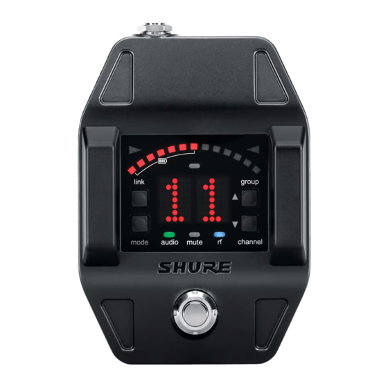
Shure GLXD6 Manual
Guitar pedal receiver with integrated tuner
Hide thumbs
Also See for GLXD6:
- User manual (68 pages) ,
- Instructions manual (18 pages) ,
- User manual (17 pages)

Related Manuals for Shure GLXD6


Summary of Contents for Shure GLXD6
- Page 1 GLXD6 Guitar Pedal Receiver with Integrated Tuner The Shure GLXD6 Guitar Pedal Receiver user guide. Version: 4.1 (2020-K)
-
Page 2: Table Of Contents
LED Status During Charging Detune Charging Times and Transmitter Runtimes Sharps and Flats Installing Transmitter Batteries Reference Pitch Important Tips for Care and Storage of Shure Recharge able Batteries Using the Tuner Transmitter Battery Meter Needle Mode Strobe Mode Multiple Receiver Systems... - Page 3 Shure Incorporated Connect to the Computer Specifications Pin Assignments Troubleshooting Output Connections Resetting Components Certifications Resetting the Receiver Resetting the Transmitter Information to the user Australia Warning for Wireless 3/33...
-
Page 4: Glxd6 Guitar Pedal Receiver With Integrated Tuner
Shure Incorporated GLXD6 Guitar Pedal Receiver with Integrated Tuner IMPORTANT SAFETY INSTRUCTIONS READ these instructions. KEEP these instructions. HEED all warnings. FOLLOW all instructions. DO NOT use this apparatus near water. CLEAN ONLY with dry cloth. DO NOT block any ventilation openings. Allow sufficient distances for adequate ventilation and install in accordance with the manufacturer’s instructions. -
Page 5: Warning
EMC performance. • Use this battery charger only with the Shure charging modules and battery packs for which it is designed. Use with other than the specified modules and battery packs may increase the risk of fire or explosion. -
Page 6: Accessories
Shure Incorporated Accessories Included Components Shure Rechargeable Battery SB902A Micro USB Battery Charger SBC10-USB Power Supply PS24 Premium Guitar Cable WA305 Quick Start To reduce set up time, the transmitter and receiver automatically link to form an audio channel the first time they are powered on and never have to be linked again. -
Page 7: Display Screen, Indicators, And Controls
Shure Incorporated Guitar Pedal Receiver Overview ① Power Switch Turns power on or off. Connect DC power supply (9 to 15 V DC, 250 mA min.) ② DC Power Connector Note: Compatible with positive tip or negative tip power supplies. -
Page 8: Tuner Mode
Shure Incorporated ① Transmitter Battery Me Illuminated segments indicate remaining battery life Group Channel ② Display LK (controls locked) UN (controls unlocked) -- (frequency not available) ③ Link Button Press to manually link receiver to a transmitter or to activate the remote ID function ④... -
Page 9: Bodypack Transmitter
Shure Incorporated ⑦ Frequency Detuned/Ref A dot is displayed when the tuning or pitch has be set to a non-standard value. erence Pitch Offset indica Note: Non-standard turning or pitch settings scroll across the receiver display during power-up. Bodypack Transmitter ①... -
Page 10: Transmitter Status Led
For best results, the belt should be pressed against the base of the clip. Batteries and Charging GLX-D transmitters are powered by Shure SB902A lithium-ion rechargeable batteries. Advanced battery chemistry maximizes runtimes with zero memory effects, eliminating the need to discharge batteries prior to charging. -
Page 11: Charging From An Ac Power Source
Shure Incorporated The following battery charging options are available: Charging from an AC Power Source Plug the charging cable into the charging port on the transmitter. Plug the charging cable into an AC power source. Charging from a USB Port Plug the USB charging cable into the charging port on the transmitter. -
Page 12: Installing Transmitter Batteries
Close the battery door and slide door to engage the latch. Important Tips for Care and Storage of Shure Rechargeable Batteries Proper care and storage of Shure batteries results in reliable performance and ensures a long lifetime. • Always store batteries and transmitters at room temperature •... -
Page 13: Multiple Receiver Systems
Shure Incorporated Multiple Receiver Systems For ease of set up, frequencies are divided into groups to best match the channel requirements for your system. Select the group by determining the total number of receivers in your system (channel count). All receivers in the system must be set to the same group. -
Page 14: Manually Selecting A Group And Channel
Shure Incorporated Note: Dashes appearing on the group and channel display during a channel scan indicate that frequencies are not available in the selected group. Choose a group that supports more receivers and repeat the set up steps. Manually Selecting a Group and Channel Specific groups and channels can be assigned to the receiver instead of using the automatic scan function. -
Page 15: 2.4 Ghz Spectrum Overview
Shure Incorporated After linking the transmitters, gain settings can be set and stored independently for each transmitter. Important! Do not turn on and operate both linked transmitters at any time. Turn off both transmitters before beginning. Press the group button to select a group. The receiver automatically scans the selected group to find the best available channel. -
Page 16: Tips And Methods To Improve Wireless System Perfor- Mance
Shure Incorporated Tips and Methods to Improve Wireless System Perfor- mance If you encounter interference or dropouts, try the following suggestions: • Scan for the best available channel (press the channel button) • Reduce transmitter to receiver distance - for example, place receivers on stage with a line of sight to the receiver. -
Page 17: Receiver Operation
Shure Incorporated Group/Channel Frequencies 2410 2411 2431 2432 2448 2449 2417 2418 2451 2452 2468 2469 2437 2438 2462 2463 2477 2478 Group 3: Channels 1-8 (latency = 7.3 ms) Group/Channel Frequencies 2415 2416 2443 2422 2423 2439 2426 2427 2457... -
Page 18: Locking And Unlocking The Controls
Shure Incorporated Locking and Unlocking the Controls The controls of the receiver and transmitter can be locked to prevent accidental or unauthorized changes to settings. The following parameters are not affected by locking the controls: • Lock status is not changed by power cycles •... -
Page 19: Tuner Menu
Shure Incorporated Tuner Menu Enter tuner mode by pressing the footswitch. In tuner mode, the controls will only affect tuner functions, RF and audio settings are not affected. Note: The audio signal does not pass through the tuner, eliminating the need for bypass switches commonly found on wired tuners. -
Page 20: Indicator: Needle Or Strobe
Shure Incorporated Indicator: Needle or Strobe The tuner indicator can be set to display a needle style or strobe style. Needle A single LED will illuminate on the tuning bar to indicate sharp or flat. The green center LED will illuminate when the note is in tune. -
Page 21: Display Brightness
Shure Incorporated Display Brightness The receiver has a built-in light sensor to automatically adjust the display brightness. To manually adjust the brightness choose one of the following settings: Detune The tuner can be set to display standard tuning for instruments that have been detuned up sharp or flat in the following incre... -
Page 22: Sharps And Flats
Shure Incorporated * dot appears on the display as a reminder that the pedal is detuned. Sharps and Flats Adds sharp or flat symbols to the display of non-natural notes. Reference Pitch The reference pitch can be offset from standard A440 in a range of 432 Hz to 447 Hz in 1 Hz increments. -
Page 23: Strobe Mode
Shure Incorporated Strobe Mode Both tuning indicators will illuminate and the strobe segments will remain stationary when the note is in tune. 23/33... -
Page 24: Using A Third-Party Power Supply
Shure Incorporated Using a Third-Party Power Supply To power your GLXD6 wireless receiver pedal, we recommend using the included power supply or a power supply with isolated power outputs. If using a power supply with isolated power outputs, use a power outlet rated at a minimum of 250 mA. -
Page 25: Firmware
Firmware is embedded software in each component that controls functionality. Periodically, new versions of firmware are devel oped to incorporate additional features and enhancements. To take advantage of design improvements, new versions of the firmware can be downloaded and installed using the Shure Update Utility tool. Software is available for download from http://www.shure.com/update-utility. -
Page 26: Troubleshooting
Transmitter and receiver Update both components to firmware ver LEDs flash to indicate sion 2.0 or greater. Download the Shure Up Transmitter and receiver link unsuccessful that linking started, but date Utility application and follow the instruc the link fails tions. -
Page 27: Resetting Components
Shure Incorporated Issue Indicator Status Solution Sound level variations when switching to dif Adjust transmitter gain as necessary (see ferent sources Gain Adjustment). Transmitter LED flash Controls locked. See Locking and Unlocking Receiver/transmitter won't turn off ing rapidly Controls. Check transmitter. Transmitter must be on to Receiver gain control cannot be adjusted enable gain changes. -
Page 28: Resetting The Transmitter
Indoor (200 ft) maximum Up to 20 m (65 ft) typical , Up to 50 m (165 ft) Outdoor maximum Transmit Mode Shure proprietary digital Audio Frequency Response 20 Hz – 20 kHz Dynamic Range 120 dB, A-weighted RF Sensitivity... - Page 29 Shure Incorporated Storage Temperature Range -29°C (-20°F) to 74°C (165°F) Polarity Positive voltage applied to the tip of the guitar cable phone plug produces positive voltage at the tip of the high impedance ¼-inch output. Battery Life Up to 16 hours...
-
Page 30: Pin Assignments
Shure Incorporated Transmitter Input Connector 4-Pin male mini connector (TA4M) Configuration Unbalanced Maximum Input Level 1 kHz at 1% THD +8.4 dBV (7.5 Vp-p) Antenna Type Internal Monopole Pin Assignments TA4M ground (cable shield) + 5 V Bias audio Tied through active load to ground (On instrument adapter cable, pin 4 floats) - Page 31 Shure Incorporated (17.8 oz.) Housing Cast Metal, Black Powdercoat Power Requirements 9 to 15 V DC, 250 mA min. Spurious Rejection >35 dB, typical Gain Adjustment Range -20 to 40 dB in 1 dB steps Audio Output Configuration 6.35 mm (1/4") output...
-
Page 32: Output Connections
This product meets the Essential Requirements of all relevant European directives and is eligible for CE marking. Hereby, Shure Incorporated declares that the radio equipment is in compliance with Directive 2014/53/EU. The full text of the EU declaration of conformity is available at the following internet address: http://www.shure.com/europe/compliance... -
Page 33: Information To The User
万一、この機器から移動体識別用の構内無線局に対して有害な電波干渉の事例が発生した場合には、 速やかに使用周波 数を変更するか又は電波の発射を停止した上、下記連絡先にご連絡頂き、混 信回避のための処置等(例えば、パーティ ションの設置など)についてご相談して下さい。 その他、この機器から移動体識別用の特定小電力無線局あるいはアマチュア無線局に対して有害な電波干渉の事例が発生 した場合など何かお困りのことが起きたときは、保証書に記載の販売代 理店または購入店へお問い合わせください。代 でもご覧いただけます。 理店および販売店情報は Shure 日本語ウェブサイト http://www.shure.co.jp 現品表示記号について 現品表示記号は、以下のことを表しています。 この無線機器は 2.4GHz 帯の電波を使用し、変調方式は「その他」の方式、想定与 干渉距離は 80m です。 2,400MHz~ 2,483.5MHz の全帯域を使用し、移動体識別装置の帯域を回避することはできません。 Information to the user This equipment has been tested and found to comply with the limits for a Class B digital device, pursuant to Part 15 of the FCC Rules.