
Related Manuals for SMC Networks LEC-GPR1 Series


Summary of Contents for SMC Networks LEC-GPR1 Series
- Page 1 Doc.no. LEC-OM03403 Product name Electric actuator controller Gateway (GW) unit (Profibus type) Model / Series LEC-GPR1...
-
Page 2: Table Of Contents
Contents 1. Safety Instructions..............4 2. Outlines of Product ..............7 2. 1 Features........................ 7 2. 2 How to Order ...................... 7 2. 3 Structure of the product ................8 2. 4 Procedure (How to start the actuator) ........... 9 (1) Checking the content of the package .......... - Page 3 6.1 Power supply connector................. 25 6.2 Power line ......................25 6.3 Wiring of the shutdown circuit..............26 【Shutdown circuit Example】 ..............28 7. CN3: Bus conecter ..............29 8. CN1: Controller IF communication connector (CONT)30 8. 1 Connection......................30 8. 2 Wiring diagram....................32 9.
- Page 4 15.5 Maintenance ..................... 53 15.6 Precautions for actuator with lock............53 16. Gateway unit and its peripheral devices /Specific product precautions 54 16.1 Design and selection ..................54 16.2 Handling......................54 16.3 Mounting......................55 16.4 Electrical wiring ....................56 16.5 Power supply ....................56 16.6 Grounding......................
-
Page 5: Safety Instructions
LEC-G Series/Gateway unit 1. Safety Instructions These safety instructions are intended to prevent hazardous situations and/or equipment damage. These instructions are categorized into three groups, "Caution", "Warning" and "Danger" depending on the level of hazard and damage, and the degree of emergency. They are all important notes for safety and must be followed in addition to International Standards (ISO/IEC), Japan Industrial Standards (JIS)*1) and other safety regulations*2). - Page 6 Warning (4) Contact SMC beforehand and take special consideration of safety measures if the product is to be used in any of the following conditions. 1. Conditions and environments outside of the given specifications, or use outdoors or in a location exposed to direct sunlight.
- Page 7 LEC-G Series/Gateway unit Safety Instructions Caution The product is provided for use in manufacturing industries. The product herein described is basically provided for peaceful use in manufacturing industries. If considering using the product in other industries, consult SMC beforehand and exchange specifications or a contract if necessary.
-
Page 8: Outlines Of Product
2. Outlines of Product 2. 1 Features The gateway unit (GW unit, hereafter) is the unit to connect the electric actuator controller (LEC series) to Profibus. One unit can control up to 5 same type of controllers. Caution When the device is set up or failure occurs, please refer the operation manual of the controller, the actuator, and the teaching box as well as this operation manual. -
Page 9: Structure Of The Product
2. 3 Structure of the product The system aplies this unit consists of the unit below. System structure drawing. Teaching box LEC-T1-3□G□ Profibus Term inati ●Controller setting software Gateway unit LEC-W2 LEC-GPR1□ LEC serial communication (RS485) Modbus communication Terminati on Resistor Motor controller ・... -
Page 10: Procedure (How To Start The Actuator)
2. 4 Procedure (How to start the actuator) Install, wire, set and operate the gateway unit referring to the procedure below when the product is used for the first time. (1) Checking the content of the package After unpacking, check the description of the label to identify the gateway unit and the quantity of accessories. -
Page 11: Power Supply
(6) Power supply Supply power 24V DC. Caution 0V line of the gateway unit and the motor controller (LEC) have to be common. When power is supplied in order of the gateway unit, then the controller (LEC), reset the data link after supplying power to the controller (LEC). -
Page 12: Specifications
3. Specifications 3. 1 Specifications Basic specifications of the product. Item Specifications Rated voltage 24 VDC±10% Current consumption 200mA or less (When teaching box is not connected) 300mA or less (When teaching box is connected) Applicable controller Electric actuator controller (LEC series) Product to be connected Max. - Page 13 【Conditions of environment 】 Item Specifications Applicable ambient temperature 0~40℃(No freezing) Applicable ambient humidity 90%RH or less (No condensation) Atmosphere No corrosive gas, flammable gas, oil mist, or particles. Storage temperature -10~60℃(No freezing) Storage humidity 90%RH or less (No condensation) Vibration 4.9m/s (0.5G) or less...
-
Page 14: Details Of Parts
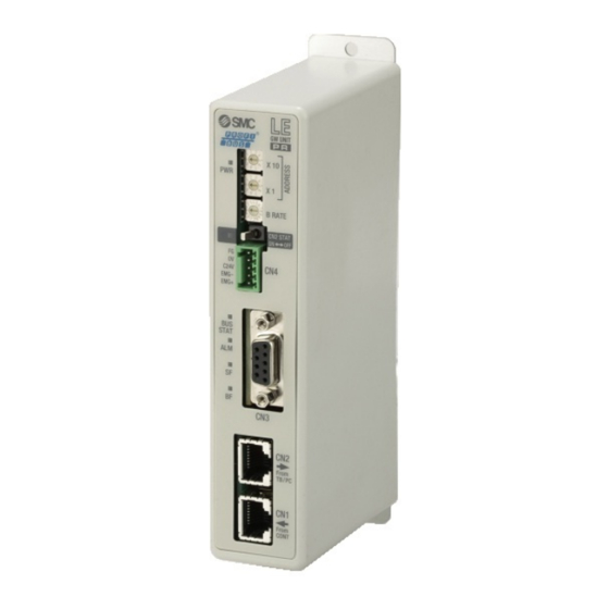
3. 2 Details of parts Details of parts of the gateway unit Display Description Detail LED lamp LED to indicate the condition of the gateway unit ADDRESS Address switch This switch sets X1 and X10 in the address. Communication The switch to set the communication speed of the B RATE speed controller IF communication line. -
Page 15: Outside Dimension Diagram
3.3 Outside dimension diagram The outside view of this product is as shown in the diagram below: (1) Screw mount type (LEC-GPR1) (2) DIN rail mount type (LEC-GPR1D) - 14 -... -
Page 16: How To Install
3.4 How to install (1) How to install There are two types of controllers; screw mount type and DIN rail mount type. The followings are the descriptions on how to install each type: [1] Screw mount type (LEC-GPR1) [2] DIN rail mount type (LEC-GPR1D) (Installation with two M4 screws) (Installation with the DIN rail) DIN rail is locked. -
Page 17: Initial Setting
4. Initial Setting 4. 1. Switch (Address, B RATE) The address of the gateway unit, and the transmission rate of motor controller LEC are set. Table below shows the setting of switches. The address is shown. (0~99) The treble is shown about the transmission rate of controller IF ●... -
Page 18: Setting The Switch To Change The Communication (Cn2Sw)
4. 2. Setting the switch to change the communication (CN2SW) Turn ON the communication switch (CN2SW) during Profibus control. If the communication switch (CN2SW) is turned off during Profibus control, communication error (data link error) is generated in the gateway unit. Turn OFF communication switch (CN2SW) when changing the setting of controller (LEC) by connecting the teaching box (LEC-T1-□) of setting software (LEC-W2) to PC/TB connector (CN2). -
Page 19: Setting Of Controller (Lec)
4. 3. Setting of controller (LEC) Initial parameter setting is necessary for the controller (LEC) which is connected to the gateway unit. Set the following by directly connecting the teaching box (LEC-T1-□) or the setting software to the controller (LEC) before connecting the gateway unit. Check the operation manual of the controller (LEC) and the teaching box (LEC-T1-□) when setting the controller (LEC). - Page 20 (2) Set the controller so that the communication speed can be changed. Change "Parameter protect" setting so that "Communication speed" parameter can be changed. View the parameters of the controller. (2)-1 Change parameter protect to [3: Common + Extend + Step]. (2)-2 Select Download.
- Page 21 (4) Change item "Parameter protect" using “Basic” tab of the display of (2) to "1: Common + Step data" and click download. (5) Close the ACT Controller software (LEC-W2) and turn OFF the controller (LEC) power supply. The changed communication speed will be valid from the next time the controller (LEC) is turned on. Caution The communication speed of the gateway unit and the controller (LEC) must match.
-
Page 22: Siemens Plc S7 Connection Method
4. 4 SIEMENS PLC S7 Connection Method Below is an explanation of the LEC-GPR1 connection method with a SIEMENS PLX STEP7 4.4.1 GSD File Installation After STEP7TM has been stated. Open[Hardware Configuration] screen. Select “Opton-Install New GSD” From the mwnu var. Select GSD File, and click the Open button. - Page 23 4.4.3 Adding Units Select “Anybus-CC PROFIBUS DP-V1” from the station window. Drag and drop the connected unit from [Hardware Catalogue] Windws. ・Input16word ・Input16word Input Total 57words ・Input16word ・Universal module I/O Type: Input,Length: 9,Unit: Words,Consistent over: Total length ・Output16word ・Output16word Output Total 57words ・Output16word ・Universal module I/O Type: Output,Length: 9,Unit:Words,Consistent over: Total length...
-
Page 24: External Connection
5. External connection 5. 1 CN4: Power supply connector Connect the power supply. The gateway unit and the controller (LEC) should have the common 0V line. Gateway Unit Power supply (24 VDC) Power supply line CN4 (Cables, PLC and power supply are prepared by customer) * Refer to 6. -
Page 25: Cn2: Pc/Tb Connector
Caution Do not pull out the cable between the gateway unit and the cable, or cut off the power supply to the controller (LEC). Communication is interrupted. 5. 4 CN2: PC/TB connector The connector which connects the tools teaching box (LEC-T1-3*G*) or PC (LEC-W2) for setting the controller (LEC. -
Page 26: Cn4: Power Supply Connector
6. CN4: Power supply connector 6.1 Power supply connector Specifications of the communication connector in accessory terminal Function Functional explanation EMG + EMG signal output + Output terminal of the emergency stop switch of the teaching box. EMG - EMG signal output - C 24V Power supply + terminal Power supply terminal of the Gateway unit... -
Page 27: Wiring Of The Shutdown Circuit
Caution (1) The earthling should be the dedicated grounding point. It should be a functional ground with less than 100 Ω resistance. (2) The ground point should be near this gateway unit to make the wire length shorter. Gateway unit Other device Other device Gateway unit... - Page 28 Caution Turn on the communication switch (CN2SW) before install / removal of the teaching box to / from the gateway unit. If EMG+ and EMG- terminals are connected to the controller (LEC) or a shutdown circuit and the communication switch is turned off when the teaching box is not connected, connected controller (LEC) or the shutdown circuit receives stop signal (Open between EMG+ and EMG-) and operation stops - 27 -...
-
Page 29: Shutdown Circuit Example
【Shutdown circuit Example】 Shutdown circuit with gateway Check the circuit referring the controller (LEC) operation manual. 【Example of the circuit】ex. LEC6 DC24 Shutdown is lifted Switch Stop Switch Gateway EMG + Surge suppressor Unit EMG - Power supply plug (1st. unit) BK RLS C 24V Controller... -
Page 30: Cn3: Bus Conecter
7. CN3: Bus conecter BUS: D-sub 9-pin socket Designation Description Unused Unused 5 9 RXD・TXD-P Receive/transmit data,positive 4 8 3 Unused 7 2 DGND Data ground(reference potential 6 1 to VP) Power supply puluse (P5V) Unused RXD/TXD-N Receive/transmit data,negative Unused Use the PROFIBUS DP connector with bus cable. -
Page 31: Cn1: Controller If Communication Connector (Cont)30
8. CN1: Controller IF communication connector (CONT) 8. 1 Connection One unit can control up to 5 pcs. of controllers (LEC). The example of link connection which consists of telecommunication cable LEC-CG 1-1 and cable LEC-CG 2-1 between branches is shown below. 3 LEC-CG2-□... - Page 32 Recommended connector Description Part number RJ45 male connector with a shield(8P) TM21P-88P [HIROSE ELECTRIC CO., LTD.] M12 4pinmale connector HR24-8DJ4PE550A(73) [HIROSE ELECTRIC CO., LTD.] XS2G-D4** [OMRON Corporation] M12 4pin female connector HR24-8DP4S300(73) [HIROSE ELECTRIC CO., LTD.] XS2C-D4** [OMRON Corporation] - 31 -...
-
Page 33: Wiring Diagram
8. 2 Wiring diagram For you reference, the example of wiring of the gateway unit CN1 is shown below. The communication line from the gateway unit CN1 branches to each controller (LEC) by the branch connector. It is recommended to connect the terminating resistor (120Ω 1/4W) to the branch connector at the terminal. -
Page 34: Cn2: Tb/Pc Connector
9. CN2: TB/PC connector 9. 1 How to use This connector is for setting the controller (LEC) which is connected to the gateway unit by the teaching box or the set software. When the communication switch (CN2SW) is turned off, the communication from Profibus DP to the controller is disconnected, and the signal line of CN2 and CN1 is connected. -
Page 35: Led Display
10. LED display 10. 1 LED display LED name Content Power supply Power is not supplied status is displayed Green On Power is supplied CN2STAT ON, OFF status of When switch ON SN2SW Green ON When switch OFF Controller IF Green flashing Communicating STAT... -
Page 36: Controller If Communication Status And Led Display
10. 2 Controller IF communication status and LED display Gateway unit status BUS STAT CN2 STAT Supply of power Green On Controller (LEC) and normal Green On Green Green communication flashing flashing Command to interrupt data link is being Green On Green given flashing... -
Page 37: Mode
11. Mode 11. 1 Outline This unit has 3 types of operation mode. These modes can be switched by mode change. Current mode can be checked by mode return Refer to “12.4(1) Return of the mode” for “Return of the Mode”. ●Step data input mode Operating actuator by using the memory of the gateway unit which corresponds to parallel IO of controller (LEC). - Page 38 ●Operation commanded by numerical data input mode (ID=1) (1) Write “0” in Q_Address 16 . (2) Write the motion profile (position, speed…) in Q_Address 17 to 33. Refer to "7.1 Step data" of the operation manual of the controller(LEC). (3) Write “1” in Q_Address 16. Then, the command of the driving is sent to the controller (LEC). (4) When the sending to the controller(LEC) is completed, “Sending completed”...
-
Page 39: Data Writing Mode
Data writing mode 11. 4. This is the mode that the step data of the controller(LEC) can be changed through the gateway unit. After changing it, the changed step data is reflected by commanding to drive the changed step data. And the same functions as step data input mode are available in this mode. -
Page 40: Memory Map
12. Memory map 12. 1 Memory assignment ● Gateway unit --> Higher level device [IN] Corresponding I_Address Data name mode Gateway unit control flag All modes Unused (Do not use it.) Correspond- Bit/Byte Model/ Value Corresponding I_Address Data name Unit Ing ID range Size... - Page 41 Correspond- Bit/Byte Data Model/ Correspond- Value range Unit ing ID Address name Size Ing mode Current 4 +/-2147483647 0.01mm position Current 0 to 65500 mm/s Numerical data speed input Current 0 to 300 Force Target 4 +/-2147483647 0.01mm position Alarm 0 to 255 Alarm 0 to 255...
- Page 42 ● Higher level device --> Gateway unit [OUT] Corresponding Q_Address Data name mode Gateway unit status flag All modes Unused (Do not use it.) Bit/Byte Correspond- Model/ Corresponding Data name Value range Unit ing ID Address Size mode 0 IN0 1 IN1 2 IN2 3 IN3...
- Page 43 Bit/Byte Correspond Model/ Correspond Data name Value range Unit -ing D Address Size -ing mode 0: no send Numerical Start flag 1: send data input Step data No 0 to 63 Data writting Operation 1: Absolute 2: Relative Note) Speed 0 to 65500 mm/s Position...
-
Page 44: Controller If Status Flag(In Data
12. 2 Controller IF status flag(IN Data) Controller IF flag is sent back to each ID ID=1 is shown below as an example [ID=1] I_Address - - - - - Abnormal - Connect station station Sending - - - - -... - Page 45 (2) READY 1 (ON) appears when the gateway is activated. (3) ALARM 1 (ON) appears when one or more abnormal station are present, and the alarm is generated. 0 (OFF) appears when alarm is not generated. (4) Initial 0 (OFF) appears during processing the initial for check the connect station. 1 (ON) appears when the processing of the initial is completed.
-
Page 46: Gateway Unit Control Flag(Out Data
12. 4 Gateway unit control flag(OUT Data) The flag to control the gateway communication status. Q_Address Stop Restart Reset Mode command Setting numerical data Setting the final station number (1) Mode command Command the mode. Mode return is updated when the set mode becomes valid. Address0 Mode name Bit1... -
Page 47: Precautions For Controlling The Controller (Lec)
13. Precautions for controlling the controller (LEC) 13. 1. Communication delay between the gateway unit unit and the controller(LEC) There is communication delay between the gateway unit and the controller (LEC). Please refer to the procedure below for the control procedure taking the delay into consideration For details of each signal, please refer to the operation manual of each motor controller (LEC) to be connected. -
Page 48: Guideline Of The Response Delay Between The Gateway And The Motor Control Unit
13. 2. Guideline of the Response delay between the Gateway and the Motor Control Unit The gateway unit communicates with the motor controller (LEC) to read the controller status and commands the controller. The time for the communication causes delay in the response. Please take this into consideration when selecting the PLC program. -
Page 49: Wiring Of Cables/Common Precautions
14. Wiring of cables/Common precautions Warning Adjusting, mounting or wiring change should never be done before shutting off the power supply to the product. Electrical shock, malfunction and damaged can result. Never disassemble the cable. Use only specified cables. Never connect or disconnect the cable or connector with power on. Caution Wire the connector securely. -
Page 50: Electric Actuators/Common Precautions
15. Electric actuators/Common precautions 15.1 Design and selection Warning 1. Be sure to read the Operation Manual. Handling or usage/operation other than that specified in the Operation Manual may lead to breakage and operation failure of the product. Any damage attributed to the use beyond the specifications is not guaranteed. 2. -
Page 51: Mounting
Do not use the product in applications where excessive external force or impact force is applied to it. The product can be damaged. Each component that includes motor is made with accurate tolerance. So even slightly deformed or miss-alignment of component may lead operation failure of the product. -
Page 52: Handling
15.3 Handling Warning Do not touch the motor while in operation. The surface temperature of the motor can increase to approx. 90oC to 100oC due to operating conditions. Energizing alone may also cause this temperature increase. As it may cause burns, do not touch the motor when in operation. -
Page 53: Operating Environment
[Unpackaging] Caution 1. Check the received product is as ordered. If a different product is installed from the one ordered, injury or damage can result. 15.4 Operating environment Warning Avoid use in the following environments. a. Locations where a large amount of dusts and cutting chips are airborne. b. -
Page 54: Maintenance
15.5 Maintenance Warning Do not disassemble or repair the product. Fire or electric shock can result. Before modifying or checking the wiring, the voltage should be checked with a tester 5 minutes after the power supply is turned off. Electrical shock can result. Caution Maintenance should be performed according to the procedure indicated in the Operating Manual. -
Page 55: Gateway Unit And Its Peripheral Devices /Specific Product Precautions
16. Gateway unit and its peripheral devices /Specific product precautions 16.1 Design and selection Warning 1. Be sure to apply the specified voltage. Otherwise, a malfunction and breakage of the gateway unit may be caused. If the applied voltage is lower than the specified, it is possible that the load cannot be moved due to an internal voltage drop. -
Page 56: Mounting
9. Do not use in an area where dust, powder dust, water or oil is in the air. It will cause failure or malfunction. 10. Do not use in an area where a magnetic field is generated. It will cause failure or malfunction. 11. -
Page 57: Electrical Wiring
16.4 Electrical wiring Warning 1. Do not apply any excessive force to cables by repeated bending, tensioning or placing a heavy object on the cables. It may cause an electric shock, fire, or breaking of wire. 2. Connect wires and cables correctly. Incorrect wiring could break he gateway unit or its peripheral devices depending on the seriousness. -
Page 58: Maintenace
16.7 Maintenace Warning 1. Perform a maintenance check periodically Confirm wiring and screws are not loose. Loose screws or wires may cause unintentional malfunction. 2. Conduct an appropriate functional inspection after completing the maintenance. In case of any abnormities (in the case that the actuator does no move, etc.), stop the operation of the system. - Page 59 Revision history No.LEC-OM03401 Feb/2012 1st printing No.LEC-OM03402 Mar/2012 Revision No.LEC-OM03403 Apr/2012 Revision Addition to notes about UL recognition 4-14-1, Sotokanda, Chiyoda-ku, Tokyo 101-0021 JAPAN Tel: + 81 3 5207 8249 Fax: +81 3 5298 5362 URL http://www.smcworld.com Note: Specifications are subject to change without prior notice and any obligation on the part of the manufacturer. ©...