Advertisement
Quick Links
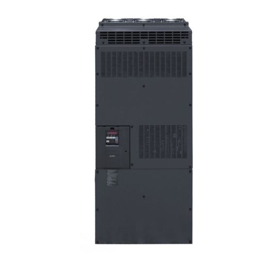
INVERTER
FR-CC2 Converter Unit
INSTALLATION GUIDELINE
FR-CC2-H315 kW to H630 kW
Thank you for choosing this Mitsubishi converter unit.
This Installation guideline gives handling information and precautions for use of this product.
Do not use this product until you have a full knowledge of the equipment, the safety information and the
instructions.
Please forward this Installation guideline to the end user.
INSTALLATION AND INSTRUCTIONS.....................................................................1
1
2
WIRING ......................................................................................................................3
3
PRECAUTIONS FOR USE OF THE CONVERTER UNIT .......................................19
4
DRIVE THE MOTOR ................................................................................................20
5
TROUBLESHOOTING .............................................................................................24
6
SPECIFICATIONS....................................................................................................26
Art. No.: 280308
10 08 2018
Version B
Version check
CONTENTS
Advertisement

Related Manuals for Mitsubishi Electric FR-CC2


Summary of Contents for Mitsubishi Electric FR-CC2
-
Page 1: Table Of Contents
INVERTER FR-CC2 Converter Unit INSTALLATION GUIDELINE FR-CC2-H315 kW to H630 kW Thank you for choosing this Mitsubishi converter unit. This Installation guideline gives handling information and precautions for use of this product. Do not use this product until you have a full knowledge of the equipment, the safety information and the instructions. - Page 2 10/2014 280308-A First edition 08/2018 280308-B Addition: FR-CC2-H560 kW, H630 kW Supplement BCN-C22005-733-A Change: All connection diagrams appear with the control logic of the input terminal as source logic. For Maximum Safety Mitsubishi transistorized inverters and converter units are not designed or manufactured to be used in equipment or systems in situations that can affect or endanger human life.
- Page 3 A person who took a proper engineering training. Please note if you can take a proper engineering training at your local Mitsubishi Electric office. Such training may be available at your local Mitsubishi Electric office. Contact your local sales office for schedules and locations.
- Page 4 Use the converter unit under the following environmental conditions. Otherwise, the converter unit may be damaged. Operating condition FR-CC2 Surrounding air FR-CC2-H315 kW to H560 kW: –10 °C to +50 °C (non-freezing) temperature FR-CC2-H630 kW: –10 °C to +40 °C (non-freezing)
- Page 5 Emergency stop CAUTION Provide a safety backup such as an emergency brake which will prevent the machine and equipment from hazardous conditions if the converter unit fails. When the breaker on the converter unit's input side trips, check for the wiring fault (short circuit), damage to internal parts of the converter unit, etc.
-
Page 7: Installation And Instructions
1 INSTALLATION AND INSTRUCTIONS 1.1 Converter unit model Symbol Voltage class Symbol Description 400V class 315 to 630 kW Rated converter unit capacity [kW] F R- C C 2 - H 315 kW -60 Circuit board coating Symbol (conforming to Plated conductor IEC60721-3-3 3C2/3S2) With... - Page 8 10cm Vertical 20cm For replacing the cooling fan 30cm of space is necessary in front of the converter unit. Refer to the FR-CC2 Instruction Manual for fan replacement. 1.3 Environment Before installation, check that the environment meets following specifications: Enclosure...
-
Page 9: Wiring
2 WIRING 2.1 Terminal connection diagrams Source logic Connection is not available Source logic Inverter Main circuit terminal DC reactor Control circuit terminal MCCB Inrush current R/L1 3-phase limit circuit S/L2 AC power supply T/L3 EMC filter ON/OFF R1/L11 Jumper connector S1/L21 Main circuit... - Page 10 For manufacturer setting. Do not use. For the FR-CC2-H400 kW or higher, two EMC filter ON/OFF connectors are provided. To use RDA signal of the converter unit, select the NC contact input specification for the input logic of MRS signal or X10 signal of the inverter.
- Page 11 WIRING Sink logic Sink logic Connection is not available Inverter Main circuit terminal Control circuit terminal DC reactor MCCB Inrush current R/L1 limit circuit 3-phase S/L2 AC power supply T/L3 EMC filter ON/OFF R1/L11 Jumper connector S1/L21 Main circuit Earth Control circuit Open collector output Control input signals...
- Page 12 For manufacturer setting. Do not use. For the FR-CC2-H400 kW or higher, two EMC filter ON/OFF connectors are provided. To use RDA signal of the converter unit, select the NC contact input specification for the input logic of MRS signal or X10 signal of the inverter.
- Page 13 WIRING Connection diagram with 12-pulse rectifier power transformer The FR-CC2 converter unit can be run with 12-pulse rectifier power supply. Main circuit terminal Connection is not available Control circuit terminal Inverter MCCB DC reactor Inrush R/L1 current limit S/L2 circuit...
- Page 14 WIRING 2.2 Main circuit terminal 2.2.1 Terminal layout and wiring FR-CC2-H315 kW to FR-CC2-H630 kW R1/L11 S1/L21 Charge lamp Jumper R/L1 T/L3 S/L2 To inverter Power supply CAUTION The power supply cables must be connected to R/L1, S/L2, T/L3. (Phase sequence needs not to be matched.) When wiring the main circuit conductor tighten a nut from the right side of the conductor.
- Page 15 WIRING 2.2.2 Wiring method for 12-pulse rectifier power supply In the initial status, terminals R/L1 and R2/L12, S/L2 and S2/L22, and T/L3 and T2/L32 of the converter unit are respec- tively shorted with shorting conductors. For 12-pulse applications, remove the bolts and nuts shown in the figure below to remove the shorting conductors.
- Page 16 WIRING CAUTION Make sure to connect the power cables to the right terminals: one set to terminals R/L1, S/L2, and T/L3, and the other set to terminals R2/L12, S2/L22, and T2/L32. When wiring the main circuit conductor tighten each nut from the right side of the conductor as seen from the front of the unit.
- Page 17 Cable Sizes Crimping AWG/MCM Terminal Converter HIV, etc. [mm PVC, etc. [mm Terminal Screw Tightening model Torque [Nm] Size * Earth Earth FR-CC2-H R/L1, R/L1, R/L1, R/L1, P/+, N/– Cable Cable S/L2, T/L3 S/L2, T/L3 S/L2, T/L3 S/L2, T/L3 Gauge Gauge...
- Page 18 ≤ 50 m ≤ 30 m For the cable gauge of the cable across the main circuit terminals P/+ and N/– (P and P, N and N), refer to page 11. Converter unit Inverter FR-CC2 MCCB R/L1 S/L2 Power supply...
- Page 19 WIRING 2.4 Control circuit terminals 2.4.1 Terminal layout ∗1 ∗1 NC NC NC NC NC +24 SD NC NC NC NC PC NC NC NC SE SE IPF RSO FAN PC NC NC NC NC NC NC OH SD SD RDI NC NC For manufacturer setting.
- Page 20 WIRING Blade terminal product Insulation product Crimping tool product Cable gauge (mm²) Manufacturer number number number 0.3 to 0.75 BT 0.75-11 VC 0.75 NICHIFU Co.,Ltd. NH 69 (3) Insert the wires into a socket. When using a single wire or stranded wires without a blade terminal, push the open/close button all the way down with a flathead screwdriver, and insert the wire.
- Page 21 WIRING 2.4.4 Control logic (sink/source) change Change the control logic of input signals as necessary. To change the control logic, change the jumper connector position on the control circuit board. Connect the jumper con- nector to the connector pin of the desired control logic. The jumper connector is in the sink logic (SINK) when shipped from the factory.
- Page 22 WIRING 2.5 Compatible inverters The table below shows the inverter models compatible with the FR-CC2 converter units. FR-A800 series Inverter ND (normal duty, Motor Converter SLD (superlight duty) LD (light duty) HD (heavy duty) initial value) capacity unit Rated Rated...
- Page 23 Applicable converter Molded case circuit breaker (MCCB) or earth Magnetic contactor (MC) model leakage circuit breaker (ELB) (NF, NV type) converter unit's input side [kW] FR-CC2-H315 kW 700 A S-N600 FR-CC2-H355 kW 800 A S-N600 FR-CC2-H400 kW 900 A S-N800...
- Page 24 Motor output Applicable converter Rated input current for one breaker (MCCB) on converter unit's input model circuit [kW] (NF type) side FR-CC2-H315 kW 406 A 500 A S-N400 FR-CC2-H355 kW 454 A 600 A S-N400 FR-CC2-H400 kW 512 A 600 A...
-
Page 25: Precautions For Use Of The Converter Unit
3 PRECAUTIONS FOR USE OF THE CONVERTER UNIT The FR-CC2 converter unit is a highly reliable product, but incorrect peripheral circuit making or operation/handling method may shorten the product life or damage the product. Before starting operation, always recheck the following items: Use crimping terminals with insulation sleeve to wire the power supply and the inverter. -
Page 26: Drive The Motor
4 DRIVE THE MOTOR 4.1 Operation panel (FR-DU08) 4.1.1 Components of the operation panel (FR-DU08) ³ · » ¿ ´ ² ¶ µ ¸ ¹ º ¾ Component Name Description ³ — Not used MON: Lit to indicate the monitoring mode. Operation panel Quickly flickers twice intermittently while the protective function is ·... - Page 27 Past eight faults can be displayed. (The latest fault is ended by ".".) When no fault history exists, is displayed. Long press Monitored items can be changed. (Refer to the FR-CC2 Instruction Manual.) For the details of faults history, refer to the FR-CC2 Instruction Manual.
- Page 28 DRIVE THE MOTOR 4.2 Parameter list Set the necessary parameters to meet the load and operational specifications. Parameter setting, change and check can be performed from the operation panel. Initial Initial Parameter Name Setting Range Parameter Name Setting Range Value Value Reset selection RDB terminal...
- Page 29 DRIVE THE MOTOR Initial Initial Parameter Name Setting Range Parameter Name Setting Range Value Value RS-485 Operation panel 9999 communication retry monitor selection 1 0 to 10, 9999 count 2, 8, 13, 20, 25, Operation panel 9999 43, 44, 55, 62, RS-485 monitor selection 2 98, 9999...
-
Page 30: Troubleshooting
5 TROUBLESHOOTING When a fault occurs in the converter unit, the protective function activates, and the PU display automatically changes to one of the fault or alarm indications listed on page 25. If the fault does not correspond to any of the following errors or if you have any other problem, please contact your sales representative. - Page 31 TROUBLESHOOTING 5.2 List of alarm display Operation Panel Data Operation Panel Data Name Name Indication code Indication code External thermal relay E - - - - Faults history — E.OHT (H90) operation HOLD Operation panel lock — Parameter storage device E.PE (HB0) fault...
-
Page 32: Specifications
6 SPECIFICATIONS 6.1 Converter unit rating Model FR-CC2-H 315 kW 355 kW 400 kW 450 kW 500 kW 560 kW 630 kW Applicable motor capacity [kW] 150 % 60 s, 120 % 60 s, 110 % 60 s, 200 % 60 s, 250 % 3 s... - Page 33 SPECIFICATIONS 6.2 OUTLINE DRAWING 3-φC ∗1 ∗1 (Unit: mm) Converter unit model FR-CC2-H315 kW, H355 kW 1330 1300 FR-CC2-H400 kW, H450 kW, H500 kW, 1580 1550 H560 kW, H630 kW...
-
Page 34: Aappendix
CE marking. The authorized representative in the EU The authorized representative in the EU is shown below: Name: Mitsubishi Electric Europe B.V. Address: Mitsubishi-Electric-Platz 1, 40882 Ratingen, Germany NOTE We declare that this converter unit conforms with the EMC Directive in industrial environments and affix the CE marking on the converter unit . - Page 35 Ambient humidity 2500 m 2500 m 10000 m Maximum altitude Wiring protection For installation Class T, Class J, Class CC, or Class L fuse must be provided. FR-CC2-H 315 kW 355 kW 400 kW 450 kW 500 kW 560 kW...
- Page 36 APPENDIX Provide the appropriate fuse in accordance with the table below. FR-CC2-H Fuse type Model Manufacturer Rating 170M6011, 170M6111 700 A, 700 V AC 315 kW 170M6012, 170M6112 800 A, 700 V AC 355 kW 170M6013, 170M6113 900 A, 700 V AC...
- Page 38 Fax: +356 (0)21 / 697 817 Phone: +1 (847) 478-2100 Fax: +1 (847) 478-0328 Mitsubishi Electric Europe B.V. / FA - European Business Group / Mitsubishi-Electric-Platz 1 / D-40882 Ratingen / Germany / Tel.: +49(0)2102-4860 / Fax: +49(0)2102-4861120 / info@mitsubishi-automation.com / https://eu3a.mitsubishielectric.com...