Advertisement
Quick Links
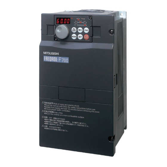
INVERTER
FR-AF700
INSTALLATION GUIDELINE
FR-AF740-00770 to 12120-EC
1
Introduction .................................................................1
2
Outline ..........................................................................1
3
Product Check .............................................................3
4
Setting Up ....................................................................5
CONTENTS
700
Advertisement

Related Manuals for Mitsubishi Electric FR-AF700-EC Series


Summary of Contents for Mitsubishi Electric FR-AF700-EC Series
- Page 1 INVERTER FR-AF700 INSTALLATION GUIDELINE FR-AF740-00770 to 12120-EC CONTENTS Introduction ..............1 Outline ................1 Product Check .............3 Setting Up ..............5...
-
Page 2: Introduction
Please forward this manual to the end user. 2 Outline The FR-AF700-EC series is a base unit of the inverter. A base unit is a main circuit section of the inverter, where three-phase AC power is converted to DC power and then converted to any three-phase AC power. - Page 3 Inverter type according to the combination of the base unit and control unit Inverter Type as a Result of Base Unit Type Control Unit Type Combination FR-CA70-EC FR-A740-00770-EC FR-AF740-00770-EC FR-CF70-EC FR-F740-00770-EC FR-CA70-EC FR-A740-00930-EC FR-AF740-00930-EC FR-CF70-EC FR-F740-00930-EC FR-CA70-EC FR-A740-01160-EC FR-AF740-01160-EC FR-CF70-EC FR-F740-01160-EC FR-CA70-EC FR-A740-01800-EC...
-
Page 4: Product Check
3 Product Check (1) Base unit • Unit type 00770 - EC FR - AF740 Symbol Voltage Class Symbol Type number Three-phase 00770 AF740 Displays the rated current 400V class 12120 Rating plate Rating plate FR-AF740-00770-EC Inverter type Input rating Output rating ND (50 C) XXA LD (50 C) XXA... - Page 5 (2) Control unit accessory • Unit type - EC FR - CA70 Compatible Base Unit Symbol Voltage Class Symbol FR-CA70 FR-CF70 Control unit for CA70 FR-A740-EC 00770 to 01800 00770 to 01160 Control unit for 02160 to 12120 01800 to 12120 CF70 FR-F740-EC Rating plate...
-
Page 6: Setting Up
4 Setting Up (1) Removal of a base unit front cover 1) Remove installation 2) Loosen the installation 3) Pull the front cover 2 toward screws on the front screws of the front you to remove by pushing an cover 1 to remove cover 2. - Page 7 Remove the sponge for connector pin protection of the control unit. Slightly tilt the control unit to insert a printed circuit board into three hooks of the base unit. Side surface of the control unit Insert this portion into a hook of the base unit.
- Page 8 Tip down the control unit to the base unit side( ) to closely attach to the base unit, then slide it downward( ). Slide it until it is firmly fixed with guides. Printed circuit board Guide Printed circuit board Guide...
- Page 9 Connect the base unit and the control unit with a cable provided with the control unit. Insert the cable side connector to the base unit connector straight until you hear a click sound of the cable side connector hooks and firmly fix it.
- Page 10 Insert the other side connector of the cable into the connector of the control unit. Insert the cable side connector until you hear a click sound of the cable side connector hooks and firmly fix it. Install the control circuit terminal block provided with the control unit using care not to bend the pins of the control circuit connector.
- Page 11 (3) Reinstallation of the front cover 1) Insert the two fixed hooks on the 2) Using the fixed hooks as supports, left side of the front cover 2 into the securely press the front cover 2 sockets of the inverter. against the inverter.
- Page 12 (4) Applying a logo sticker Apply a sticker provided with the control unit on the base unit as shown below. FR-CA70-EC(ECT) FR-CF70-EC(ECT) (5) Completed When set-up is completed, it can be used as the FR-A740-EC or FR-F740-EC. Refer to the instruction manual provided with the control unit for details of operation, specifications, etc.
- Page 13 REVISIONS *The manual number is given on the bottom left of the back cover. Print Date Revision Manual Number Mar., 2006 IB(NA)-0600267ENG-A First edition May, 2006 IB(NA)-0600267ENG-B Modification Combination of the base unit and control unit...