3Com 4210 Getting Started
Switch 4210 series
Hide thumbs
Also See for 4210:
- Getting started (80 pages) ,
- Release notes (43 pages) ,
- Datasheet (8 pages)
Table of Contents
Advertisement
Advertisement
Table of Contents

Related Manuals for 3Com 4210


Summary of Contents for 3Com 4210
-
Page 1: Getting Started
® 3Com Switch 4210 Family Getting Started Switch 4210 PWR 9-Port Switch 4210 PWR 18-Port Switch 4210 PWR 26-Port Switch 4210 9-Port Switch 4210 18-Port Switch 4210 26-Port Switch 4210 52-Port www.3Com.com Part Number: 10016119 Rev. AB Published: January, 2008... - Page 2 LICENSE.TXT or !LICENSE.TXT. If you are unable to locate a copy, please contact 3Com and a copy will be provided to you.
-
Page 3: Table Of Contents
ONTENTS BOUT UIDE Download the Latest Software and Documentation for Your 3Com Switch Before You Start Related Documentation RODUCT NTRODUCTION Overview Introduction to the Switch 4210 Family PWR Switches Introduction to the Switch 4210 Family Non-PWR Models Technical Specifications SFP Modules Supported for the Switch 4210... - Page 4 Purchase Extended Warranty and Professional Services Access Software Downloads Contact Us ETWORK ANAGEMENT 3Com Network Supervisor 3Com Network Director 3Com Network Access Manager 3Com Enterprise Management Suite Integration Kit with HP OpenView Network Node Manager EDUNDANT OWER Important Safety Information L’information de Sécurité Importante Wichtige Sicherheitsinformationen Información de Seguridad Importante...
-
Page 5: About This Guide
Download the Latest Thank you for purchasing a 3Com Switch 4210. As part of our commitment to Software and bringing you the most capable and dependable network equipment, 3Com offers Documentation for free software maintenance updates and documentation updates on our website. -
Page 6: Related Documentation
● Related In addition to this guide, the Switch 4210 documentation set includes the following: Documentation ■ ■ ■ 3Com Switch 4210 Family Configuration Guide This guide contains information on the features supported by your switch and how they can be used to optimize your network. It is supplied in PDF format on the 3Com Web site. -
Page 7: Product Introduction
NMS-manageable intelligent Ethernet switches that support wire-speed Layer 2 switching. Three of the Switch 4210 Family models support industry standard IEEE 802.3af Power over Ethernet (PoE). Figure 1 displays these models and Table 1 provides a description of their features. -
Page 8: Introduction To The Switch 4210 Family Pwr Switches
Combo port. You can use either the SFP port or the 10/100/1000BASE-T Ethernet port at one time. Figure 3 shows the front panel of a Switch 4210 9-port PWR. Figure 3 Front panel of a Switch 4210 9-port PWR... - Page 9 (1) AC power socket Side panel Each Switch 4210 9-port PWR provides a security slot through which you can lock the device together with an irremovable object to prevent theft. The security slot is located on the left side panel, as shown in Figure 7.
- Page 10 (1) AC power socket Side panel Each Switch 4210 18-port PWR provides a security slot, through which you can lock the device together with an irremovable object to prevent theft. The security slot is located on the left side panel, as shown in Figure 7.
- Page 11 Figure 7 Security slot on left side panel of a Switch 4210 18-port PWR (1): Security slot If the left screw hole above the security slot is used, the security slot cannot be used. Power system Switch 4210 18-port PWR units support AC input.
- Page 12 370W; enough to power 24-Ports at full 15.4W required of the PoE standard. 3Com recommends a Redundant Power System (RPS) from Eaton Powerware for providing DC power to the Switch 4210 PWR 26-Port. For full details, refer to www.3com.com/rps. Cooling system Switch 4210 26-port PWR units each run four fans for heat dissipation.
- Page 13 They indicate the port’s active, link, duplex, and speed status. In addition, there is an A/L LED and a D/S LED on each Switch 4210 PWR model. These two LEDs indicate the port status LEDs mode. When the A/L LED is on, the port status LEDs respectively indicate the port’s active status and link status.
-
Page 14: Introduction To The Switch 4210 Family Non-Pwr Models
1: P HAPTER RODUCT NTRODUCTION Table 5 The 1000 Mbps uplink port status LED on 4210 PWR models 1000 Mbps uplink port active LED Introduction to the This section describes each Switch 4210 Family model. Switch 4210 Family Non-PWR Models... - Page 15 The Switch 4210 cools off naturally. Switch 4210 18-port Front panel The Switch 4210 18-port models provide 16 10/100Base-TX autosensing Ethernet ports, two 10/100/1000Base-T autosensing Ethernet ports, two 100/1000Base-X SFP ports, and one Console port. Each SFP port and the corresponding 10/100/1000BASE-T autosensing Ethernet port form a Combo port.
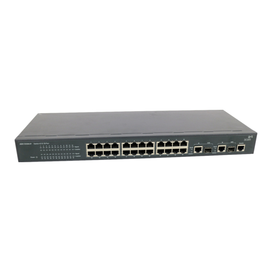
- Page 16 For each Combo port, you can use either the SFP port or the corresponding 10/100/1000BASE-T Ethernet port at one time. Figure 14 shows the front panel of the Switch 4210 26-port model. Figure 14 The Switch 4210 26-port front panel...
- Page 17 3Com Switch 4210 non-PWR models cool naturally through airflow. Switch 4210 52-port Front Panel The Switch 4210 52-port front panel provides 48 10/100Base-TX autosensing Ethernet ports, two 10/100/1000Base-T autosensing Ethernet ports, two 100/1000Base-X SFP ports (The 4 gigabit ports are all active), and one Console port.
- Page 18 Table 7 The Link/Act LED on the 3Com Switch 4210 Link/Act LED (green) Table 8 describes the Speed LED on the 10/100Base-TX port. Table 8 The 10/100Base-TX port Speed LED on the Switch 4210 10/100Base-TX autosensing port Speed LED (green) For a description of the Link/Act LED of the Combo port, see Table 7.
-
Page 19: Technical Specifications
Technical Specifications Table 10 Technical specifications for the Switch 4210 Model Switch 4210 52-port Switch 4210 26-port Switch 4210 18-port Switch 4210 9-port Physical dimensions (H 43.6 x 440 x 225 mm × W × D) (1.7 x 17.3 x 8.8 in.) Weight 12.1 lbs (5.5 Kgs) - Page 20 Number of fans Operating temperature Relative humidity (non-condensing) The Switch 4210 26-port, 18-port, and 9-port PWR models provide an over-temperature protection mechanism. When the internal temperature exceeds 65°C (149 is below 60°C (140 Related Standards The 3Com Switch 4210 Family is designed to the following standards:...
-
Page 21: Sfp Modules Supported For The Switch 4210
SFP Modules The Switch 4210’s front panel provides one or two 1000 Mbps SFP ports in which Supported for the you can plug small form-factor (SFP) modules, which are described in Table 12. Switch 4210 Table 12 SFP modules supported by the Switch 4210... - Page 22 1: P HAPTER RODUCT NTRODUCTION...
-
Page 23: Installing The Switch
NSTALLING THE WITCH ® This section contains information that you need to install and set up your 3Com switch. For information on upgrading your switch, refer to the Switch 4210 Release Notes available at www.3Com.com. WARNING: Safety Information. Before you install or remove any components... -
Page 24: Rack-Mounting The Switch
Switch 4210 26-Port and 52-Port models are rack-mountable in a standard Switch 19-inch rack. Switch 4210 9- and 18-Port models are not as wide as the 19-inch model and are intended for desktop or shelf installation. Follow the steps below to mount a 26- or 52-Port model unit in a standard 19-inch rack: 1 Check that the rack is sturdy and properly grounded. - Page 25 Front mount angle Front mount angle Mounting the rear The Switch 4210 26-Port does not need rear brackets. The description for bracket mounting rear brackets is only for the Switch 4210 PWR 24-Port. Mount a screw on the back of the switch to closely connect the switch with the rear bracket to support the switch.
- Page 26 2: I HAPTER NSTALLING THE WITCH Figure 20 Positions for screw mounting on the switch Follow the steps below to mount the rear bracket: 1 Use screws to fix the rear bracket to the rear mount angle. 2 Determine the position for screw mounting on the switch according to the position of the mount angle.
-
Page 27: Mounting The Switch On A Desktop
To place your switch on a desktop, you simply need to: ■ ■ ■ ■ The Power-up The following sections describe how to get your Switch 4210 powered-up and Sequence ready for operation. Powering-up the Switch Use the following sequence of steps to power-up the Switch. 4210 1 Plug the power cord into the power socket at the rear of the Switch. -
Page 28: Connecting A Redundant Power Supply
CAUTION: The Switch has no ON/OFF switch; the only method of connecting or disconnecting mains power is by connecting or disconnecting the power cord. Connecting a The Switch 4210 26-port PWR has a -48V DC Redundant Power Supply socket. Redundant Power Supply WARNING: Only properly trained and qualified personnel should install the Redundant Power Supply (RPS). - Page 29 WARNING: When powering any Switch 4210 from an RPS, make sure that the unit is earthed (grounded) by either connecting the power cord to the unit or by connecting the earth terminal on the rear of the unit to a reliable electrical earth (or by connecting both).
- Page 30 Table 15 shows the recommended System circuit breaker and cable rating for the Switch 4210. The recommended cable length should not exceed three metres (9.84 feet). Table 15 Switch 4210 Circuit Breaker and Cable Ratings WARNING: Make sure to follow the RPS Manufacturers recommendations when connecting the cable to the RPS.
-
Page 31: Using Power Over Ethernet
The recommended cable length should not exceed three meters (9.84 feet). Using Power over The Switch 4210 Power over Ethernet (PoE) units can supply power to any IEEE Ethernet 802.3af compliant device through any of its front panel ports over a Category 5 or Category 5e Ethernet cable. -
Page 32: Connecting The Console Cable
Ethernet cable does not require a separate power supply. If, for example, you use the switch to connect a 3Com 11 Mbps Wireless LAN Access Point 8500 to the network, then only a network cable is required to provide both power and network connectivity. - Page 33 Table 16 Console cable pinouts RJ-45 Signal Direction — <— When you want to use the terminal to configure the switch, follow these steps to connect a terminal device to your switch using console cables: 1 Plug the DB-9 female connector of the Console cable to the serial port of the PC or terminal where the switch is to be configured.
- Page 34 2: I HAPTER NSTALLING THE WITCH...
-
Page 35: Managing Your Switch
To make full use of the features offered by your switch, and to change and monitor the way it works, you have to access the management software that resides on the switch. Managing the switch can help you to improve its efficiency and therefore the overall performance of your network. -
Page 36: Methods Of Managing A Switch
The prompt for user view is <4210>. System View This view enables you to configure the system parameters. To display this view, from user view enter system-view. The prompt for system view is [4210]. Switch Console Port Connection... -
Page 37: Setting Up Your Switch
You can manage a switch using any network management workstation running the Simple Network Management Protocol (SNMP) as shown in Figure 28. For a description of 3Com network management applications refer to “3Com Network Management” on page 63. Figure 28 SNMP Management over the Network Refer to “Setting Up SNMP Management”... - Page 38 (Static IP addresses are necessary to ensure that the switch is always allocated the same IP information.) For most installations, 3Com recommends that you assign a known IP address to your switch. This makes management simpler and more reliable as it is not Power Up the Switch.
- Page 39 DHCP server. For a detailed description of how automatic IP configuration operates, refer to the Configuration Guide on the 3Com Web Site. You should use the automatic IP configuration method if: Your network uses DHCP to allocate IP information ■...
-
Page 40: Viewing Automatically Configured Ip Information
If the login prompt does not begin immediately, press Return a few times until it starts. 3 At the login and password prompts, enter Return at the password prompt. If you have logged on correctly, <4210> is displayed as shown in Figure 30. WITCH Connecting a workstation to the switch’s console port using a console cable. - Page 41 3Com Network Supervisor. Trial versions of both products are available at www.3com.com. You can use 3Com Network Supervisor or 3Com Network Director to discover the automatically allocated IP information. To do so: 1 Connect your switch to the network.
-
Page 42: Manually Configuring Ip Information
3: M HAPTER ANAGING YOUR Manually Configuring You can manually configure the switch IP information by: IP Information ■ ■ Connecting to the To set up your switch manually you can make a connection to the console port, Console Port (this example describes a local connection to the console port, rather than one using a modem). -
Page 43: Setting Up Switch With Ip Information
If the login prompt does not begin immediately, press Return a few times until it starts. 2 At the login prompts, enter admin password prompt press Return again. If you have logged on correctly, <4210> appears as shown below. Once you have logged in you are automatically in User View. *********************************************************** Switch 4210 9-Port BOOTROM, Version 4.01... - Page 44 A workstation running a suitable operating system. Refer to “Choosing a ■ Browser” on page 48. A Network Interface Card (NIC). ■ A Category 5 twisted pair Ethernet cable with RJ-45 connectors at both ends. ■ 1 23:57:15:490 2000 4210 SHELL/5/LOGIN:- 1 - admin(aux0) in prompt is [4210]...
- Page 45 A suitable Web browser. Refer to “Choosing a Browser”on page 48. ■ Existing IP address of the switch. ■ The switch’s IP information, including the: ■ IP address ■ subnet mask ■ default gateway ■ management VLAN ID, normally set to the default value (1) ■...
- Page 46 If the login prompt does not begin immediately, press Return a few times until it starts. 3 At the login prompt, enter admin as your user name and press Return at the password prompt. If you have logged on correctly, <4210> is displayed as shown below. **************************************************************************** Copyright(c) 2004-2007 3Com Corp.
-
Page 47: Setting Up Command Line Interface Management
The initial set up of your switch is now complete and you can set up your management method. See “Methods of Managing a Switch” on page 36. Setting Up Command This section describes how you can set up command line interface management Line Interface using a local console port connection or over the network. -
Page 48: Setting Up Command Line Interface Management Using Ssh
<4210>, as shown in on page 44. Setting Up Command To set up command line interface management using SSH, refer to the chapter Line Interface entitled “SSH Configuration” in the “3Com Switch 4210 Family Configuration Management using Guide.” Setting Up Web... -
Page 49: Web Management Over Network
VLAN. By default, the management VLAN is 1, and all ports on the switch are in VLAN 1. For a description of 3Com’s network management applications, see Appendix C, “3Com Network Management” on page 63. -
Page 50: Default Users And Passwords
Use the admin default user name (no password) to login and carry out initial switch setup. To set a password for the admin user in the CLI, enter the following from system view: [4210]local-user admin <cr> [4210-luser-admin]password simple xxxxxxxx (where xxxxxxxx is your chosen password). Save the configuration in the User View. -
Page 51: Problem Solving
■ If you experience a problem that is not listed here, it may be included in the Support section of the switch 4210 Command Reference Guide availabe on 3Com’s web site at www.3com.com. For Technical Support information, see “Obtaining Support for Your 3Com Products”... -
Page 52: Solving Problems Indicated By Leds
4: P HAPTER ROBLEM OLVING Solving Problems If the LEDs on the switch indicate a problem, refer to the list of suggested Indicated by LEDs solutions below. The PWR LED does not light Check that the power cable is firmly connected to the switch and to the supply outlet. -
Page 53: Solving Hardware Problems
3 Power cycle the unit. To do this, remove and reconnect the AC mains supply. If another fan failure warning message is generated using the Command Line Interface or the Web interface, return the unit to 3Com. Unit fails, no SNMP fan failure message is received 1 Power cycle the unit. -
Page 54: Solving Communication Problems
The switch has identified that the SFP does not meet the minimum requirements for the switch and has disabled the port. To correct this problem, completely remove the SFP and replace it with a 3Com approved SFP. Error message indicating that the SFP transceiver is faulty To correct this problem, completely remove the SFP and then reinsert it. -
Page 55: Solving Fabric Formation Problems
3Com suggests you use addresses in the range 192.168.0.0 to 192.168.255.255 with a subnet mask of 255.255.255.0. These suggested IP addresses are part of a group of IP addresses that have been set aside specially for use ‘in house’ only. - Page 56 4: P HAPTER ROBLEM OLVING...
-
Page 57: Pin - Outs
Null Modem Cable RJ-45 to RS-232 25-pin PC-AT Serial Cable RJ-45 to 9-pin OUTS Switch 5500 Cable connector: RJ-45 female Screen Shell Ground Switch 5500 Cable connector: RJ-45 female Screen Shell Ground PC/Terminal Cable connector: 25-pin male/female Screen only required if screen always required Ground required for handshake... -
Page 58: Modem Cable
A: P HAPTER OUTS Modem Cable RJ-45 to RS-232 25-pin Ethernet Port RJ-45 10/100 and 1000BASE-T RJ-45 connections. Pin Assignments Table 10 Pin assignments Pin Number Ports configured as MDI Table 11 Pin assignments Pin Number Ports configured as MDIX Switch 5500 Cable connector: RJ-45 female Screen... -
Page 59: Upport For Your
To take advantage of warranty and other service benefits, you must first register to Gain Service your product at: Benefits http://eSupport.3com.com/ 3Com eSupport services are based on accounts that are created or that you are authorized to access. Solve Problems Online 3Com offers the following support tool: ■... -
Page 60: Contact Us
3Com as a separately ordered product. Separately orderable software releases and licenses are listed in the 3Com Price List and are available for purchase from your 3Com reseller. - Page 61 Details about recent configuration changes, if applicable ■ To send a product directly to 3Com for repair, you must first obtain a return materials authorization number (RMA). Products sent to 3Com without authorization numbers clearly marked on the outside of the package will be returned to the sender unopened, at the sender’s...
- Page 62 Israel 180 945 3794 Italy 800 879489 You can also obtain support in this region using this URL: http://emea.3com.com/support/email.html You can also obtain non-urgent support in this region at these email addresses: Technical support and general requests: Return material authorization: warranty_repair@3com.com...
-
Page 63: Om Network Management
Director out key management and administrative tasks on midsized networks. By using 3ND you can discover, map, and monitor all your 3Com devices on the network. It simplifies tasks such as backup and restore for 3Com device configurations as well as firmware and agent upgrades. -
Page 64: 3Com Network Access Manager
C: 3C PPENDIX ETWORK To find out more about how 3Com Network Director can help you manage your 3Com network and to download a trial version, go to: www.3com.com/3nd 3Com Network Access 3Com Network Access Manager is installed seamlessly into Microsoft Active Manager Directory and Internet Authentication Service (IAS). -
Page 65: 3Com Enterprise Management Suite
The client-server offering operates on Windows and UNIX (Linux and Solaris) systems. 3Com EMS is available in four packages, varying in the maximum number of devices actively managed. These include SNMP-capable devices such as switches, routers, security switches, the 3Com VCX™ IP Telephony server, and wireless access points: ■... - Page 66 C: 3C PPENDIX ETWORK ANAGEMENT...
-
Page 67: Edundant Ower Supply Safety Information
WARNING: These instructions must be read in conjunction with the RPS flyer and the safety and installation instructions supplied with your RPS. WARNING: When powering any Switch 4210 from an RPS, the unit must be earthed (grounded). This can be achieved by either connecting the power cord to the unit or by connecting the earth terminal on the rear of the unit to a reliable electrical earth, or by connecting both. -
Page 68: L'information De Sécurité Importante
à la norme IEC 60950-1/UL 60950-1/EN 60950-1. AVERTISSEMENT: Ces instructions doivent être lues conjointement avec les caractéristiques de l'alimentation CC du Switch 4210 fournies en annexe C, Spécifications techniques. AVERTISSEMENT: Vous devez respecter les recommandations du fabricant lors du branchement du câble au module RPS. -
Page 69: Información De Seguridad Importante
VORSICHT: Diese Anleitungen müssen im Zusammenhang mit den Sicherheitshinweisen und Installationsanleitungen zu Ihrer RPS gelesen werden. VORSICHT: Bei der Stromversorgung eines Switch 4210 über eine RPS muss das Gerät geerdet sein. Hierfür kann entweder das Netzkabel an das Gerät angeschlossen werden oder die Erdungsklemme an der Rückseite des Geräts mit einer zuverlässigen elektrischen Erdung verbunden werden oder beides. - Page 70 Switch está conectado al terminal negativo (disyuntor) del RPS. ADVERTENCIA: asegúrese de que el disyuntor del RPS se encuentra en la posición de abierto (desactivado) al conectar el cable del RPS y el conector al Switch 3Com. ADVERTENCIA: No utilice un sistema de alimentación eléctrica redundante de -48 V con conexión a tierra positiva, adecuado para su uso con equipos de...
-
Page 71: Importanti Informazioni Di Sicurezza
AVVERTENZA: queste istruzioni devono essere lette insieme alle istruzioni di sicurezza e installazione fornite con l'RPS. AVVERTENZA: se si accende uno Switch 4210 da un RPS, l'unità deve disporre di messa a terra. Per accendere lo switch, è possibile collegare il cavo di alimentazione all'unità, collegare il terminale di terra situato sul retro dell'unità... - Page 72 źródła zasilania SELV zgodny z normami IEC 60950-1/UL 60950-1/EN 60950-1. OSTRZEŻENIE: Te instrukcje należy przeczytać razem z charakterystyką zasi- lającego prądu stałego przełącznika Switch 4210 opisaną w Dodatku C, Specy- fikacja techniczna. OSTRZEŻENIE: Podczas podłączania kabla do zasilacza RPS należy przestrze- gać...
-
Page 73: Regulatory Notices
Warning: This is a class A product. In a domestic environment this product may cause radio interference in which case the user may be required to take adequate measures. A copy of the signed Declaration of Conformity can be downloaded from the Product Support web page for the Switch 4210 Product Family at http://www.3com.com. Also available at http://support.3com.com/doc/Switch_4210_EU_DOC.pdf. VCCI Statement Reorient the receiving antenna. - Page 74 D: R PPENDIX EDUNDANT OWER UPPLY AFETY NFORMATION...