
Related Manuals for 3Com SUPERSTACK 4226T


Summary of Contents for 3Com SUPERSTACK 4226T
-
Page 1: Getting Started Guide
SuperStack Switch 4200 Family Getting Started Guide Switch 4226T (3C17300) Switch 4250T (3C17302) Switch 4228G (3C17304) http://www.3com.com/ Part No. DUA1730-0AAA04 Published July 2005 ®... - Page 2 Environmental Statement It is a 3Com policy to be environmentally friendly in all operations. This manual is printed on paper that comes from sustainable, managed European forests. The production process for making the pulp has a reduced AOX level (adsorbable organic halogen) resulting in elemental chlorine-free paper.
-
Page 3: Table Of Contents
Accessing Online Documentation NTRODUCING THE UPER TACK WITCH About the Switch 4200 Family Summary of Hardware Features Switch 4200 Family — Front View Detail 10BASE-T/ 100BASE-TX Ports 10/100/1000BASE-T Ports GBIC Ports LEDs Switch 4200 Family — Rear View Detail Power Socket... - Page 4 Manually Configuring IP Information Connecting to a Front Panel Port Connecting to the Console Port Viewing Automatically Configured IP Information Using 3Com Network Supervisor Connecting to the Console Port Methods of Managing a Switch Command Line Interface Management Web Interface Management...
- Page 5 Important Safety Information L’information de Sécurité Importante Wichtige Sicherheitsinformationen OUTS Null Modem Cable PC-AT Serial Cable Modem Cable RJ-45 Pin Assignments ECHNICAL PECIFICATIONS Switch 4226T (3C17300) Switch 4250T (3C17302) Switch 4228G (3C17304) BTAINING UPPORT FOR YOUR Register Your Product Purchase Value-Added Services...
-
Page 7: About This Guide
SuperStack 3 Switch 4200 Family Getting Started Guide (part number ■ DUA1730-0AAA03) available for download from the 3Com Web site, The guide is intended for use by network administrators who are responsible for installing and setting up network equipment; consequently, it assumes a basic working knowledge of LANs (Local Area Networks). -
Page 8: Conventions
BOUT UIDE Most user guides and release notes are available in Adobe Acrobat Reader Portable Document Format (PDF) or HTML on the 3Com World Wide Web site: http://www.3com.com/ Conventions Table 1 Table 1 Notice Icons Table 2 Text Conventions Convention... -
Page 9: Related Documentation
SuperStack 3 Switch Implementation Guide This guide contains information on the features supported by your Switch and how they can be used to optimize your network. It is supplied in PDF format on the CD-ROM that accompanies the Switch. SuperStack 3 Switch Management Quick Reference Guide This guide contains: a list of the software features supported by the Switch. -
Page 10: Accessing Online Documentation
CD-ROM to a suitable directory. ■ ■ 3Com recommends that you copy the Docs/reference directory as a whole to maintain the structure of the files. Documentation accompanying 3Com Network Supervisor. This is supplied on the CD-ROM that accompanies the Switch. -
Page 11: Introducing The Super Stack 3 Switch 4200 Family
For details on the Switch 26-Port (3C17300A), Switch 50-Port (3C17302A) and Switch 28-Port (3C17304A), refer to the following document: SuperStack 3 Switch 4200 Family Getting Started Guide (part number ■ DUA1730-0AAA03) available for download from the 3Com Web site, TACK WITCH 4200 www.3Com.com... -
Page 12: About The Switch 4200 Family
4200 Family consists of: ■ ■ ■ The Switch provides high-performance workgroups with a backbone to server connection. You can also add the Switch 4200 Family to any SuperStack Summary of Table 3 Hardware Features Switch 4200 Family. Table 3 Hardware features... -
Page 13: Switch 4200 Family - Front View Detail
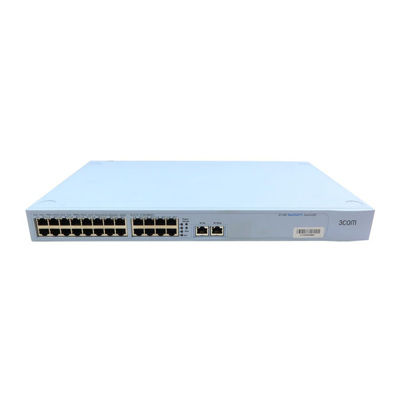
Switch 4200 Family Figure 1 Switch 4226T (3C17300) — front view — Front View Detail 10BASE-T / 100BASE-TX RJ-45 Ports 8 20 Figure 2 Switch 4250T (3C17302) — front view 10BASE-T / 100BASE-TX RJ-45 Ports 8 32 Figure 3 Switch 4228G (3C17304) — front view... -
Page 14: 10Base-T/ 100Base-Tx Ports
The 10/100/1000BASE-T ports will auto-negotiate to the appropriate speed. GBIC Ports This section applies to the SuperStack 3 Switch 4228G only. The two GBIC ports support Category 5 twisted pair cable and fiber Gigabit Ethernet short-wave (SX), long-wave (LX) and long-haul (LH70) GBIC transceivers in any combination. -
Page 15: Leds
LEDs Table 4 lists LEDs visible on the front of the Switch, and how to read their status according to color. For information on using the LEDs for problem solving, see “Solving Problems Indicated by LEDs”... - Page 16 The Switch is not receiving power or there is a fault with the Power Supply Unit. Green flashing The Switch Alert LED has been configured via the CLI or Web Interface to flash. The Switch Alert LED has been configured via the CLI or Web...
-
Page 17: Switch 4200 Family - Rear View Detail
Figure 4 Switch 4200 Family — rear view — Rear View Detail Power Socket Power Socket The Switch automatically adjusts its power setting to any supply voltage in the range 90-240 VAC. Redundant Power To protect against internal power supply failure, you can use this socket... -
Page 18: Default Settings
Table 5 Table 5 Default Settings If you initialize a Switch unit by selecting System > Control > Initialize in the Web interface or by entering system control initialize in the Command Line Interface, the following settings are retained to allow you to connect to and manage the Switch: ■... -
Page 19: Installing The Switch
GBIC Operation ■ WARNING: Safety Information. Before installing or removing any components from the Switch 4200 Family or carrying out any maintenance procedures, you must read the safety information provided Appendix A AVERTISSEMENT: Consignes de sécurité. Avant d'installer ou d'enlever tout composant du Switch 4200 ou d'entamer une procédure de... -
Page 20: Package Contents
Water or moisture cannot enter the case of the Switch. Air-flow is not restricted around the Switch or through the vents in the side of the Switch. 3Com recommends that you provide a minimum of 25mm (1in.) clearance. Air temperature around the Switch does not exceed 40 The air is as free from dust as possible. -
Page 21: Rack-Mounting
To rack-mount your Switch: 1 Place the Switch the right way up on a hard flat surface, with the front facing towards you. 2 Locate a mounting bracket over the mounting holes on one side of the... - Page 22 NSTALLING THE 3 Insert the two screws and tighten with a suitable screwdriver. 4 Repeat steps 2 and 3 for the other side of the Switch. 5 Insert the Switch into the 19-inch rack and secure with suitable screws 6 Connect network cabling.
-
Page 23: Placing Units On Top Of Each Other
The unit LEDs will display the unit number in the stack, from 1 at the bottom to 4 at the top. 3Com recommends that when you add a new unit to a stack, you should first initialize it to factory default settings. -
Page 24: The Power-Up Sequence
Use the following sequence of steps to power-up the Switch. Switch 4200 Family 1 Plug the power cord into the power socket at the rear of the Switch. 2 Plug the other end of the power cord into your power outlet. -
Page 25: Connecting A Redundant Power System
Yellow In addition, check the Unit LEDs on all Switches in the stack. If a Unit LED is off, initialization is not complete. 3Com recommends that you do not use the Switch's management interface until the Unit LED is green. -
Page 26: Choosing The Correct Fiber Cables
MDI port, you need to use a standard straight-through cable. See 3Com recommends that you use Category 5 twisted pair cable — the maximum segment length for this type of cable is 100 m (328 ft). CAUTION: If you want to install the Switch using a Category 5E or Category 6 cable, 3Com recommends that you briefly connect the cable to a grounded port before connecting network equipment. -
Page 27: Gbic Operation
■ These are correct at the time of publication. To access the latest list of approved GBIC transceivers for the Switch on the 3Com Corporation World Wide Web site, enter this URL into your internet browser: http://www.3com.com The URL is case sensitive. - Page 28 If the GBIC transceiver is faulty, it will not operate within the Switch. See “Solving Hardware Problems” Do not use non-3Com GBICs. If the GBIC transceiver is invalid it will not be recognised by the Switch. Use the following sequence of steps to activate the GBIC ports.
- Page 29 SC connector on the transceiver. 4 Connect the other end of the cable to a device fitted with an appropriate Gigabit Ethernet connection. 5 Check the LEDs on the front of the Switch to ensure that it is operating correctly. Refer to “LEDs”...
- Page 30 2: I HAPTER NSTALLING THE WITCH...
-
Page 31: Setting U P For Management
ETTING Your Switch can operate in its default state, that is, you can install it and it will work straight away (plug-and-play). However, to make full use of the features offered by the Switch, and to change and monitor the way it works, you have to access the management software that resides on the Switch. -
Page 32: Setting Up Overview
ETTING P FOR Setting Up This section gives an overview of what you need to do to get your Switch Overview set up and ready for management when it is in its default state. The whole setup process is summarised in are contained in the sections that follow. -
Page 33: Ip Configuration
(Static IP addresses are necessary to ensure that the Switch is always allocated the same IP information.) For most installations, 3Com recommends that you configure the Switch IP information manually. This makes management simpler and more reliable as it is not dependent on a DHCP or BootP server, and eliminates the risk of the IP address changing. -
Page 34: Preparing For Management
“SuperStack 3 Switch Management Interface Reference Guide” on the CD-ROM that is supplied with the Switch or on the 3Com Web site. ANAGEMENT your network uses DHCP or BootP to allocate IP information, or flexibility is needed. -
Page 35: Manually Configuring Ip Information
■ ■ Connecting to a Front To set up your Switch manually you can make a connection to a front Panel Port panel port. You must do this whilst the Switch is offline, that is, before you connect the Switch to a network. -
Page 36: Configuring Workstation With Ip Information
■ ■ Setting Up the Switch with IP Information You are now ready to manually set up the Switch with IP information. You can do this using the Web interface or the command line interface (CLI) via telnet. Using the Web Interface 1 Power-up the Switch. - Page 37 The final page displays a summary of the information entered. The initial set up of your Switch is now complete and the Switch is ready for you to set up your chosen management method. See Managing a Switch”...
-
Page 38: Connecting To The Console Port
5 Enter the IP address, subnet mask, and gateway IP address for the Switch. The screen displays a summary of the information entered. The initial set up of your Switch is now complete and the Switch is ready for you to set up your chosen management method. See Managing a Switch”... - Page 39 A workstation with terminal emulation software installed, such as ■ Microsoft Hyperterminal. This software allows you to communicate with the Switch via the console port directly, or through a modem. Documentation supplied with the terminal emulation software. ■ A suitable cable: ■...
- Page 40 Setting Up the Switch with IP Information You are now ready to manually set up the Switch with IP information using the command line interface. 1 The command line interface login sequence begins as soon as the Switch detects a connection to its console port.
- Page 41 4 Enter the IP address, subnet mask, and gateway IP address for the Switch. The screen displays a summary of the information entered. The initial set up of your Switch is now complete and the Switch is ready for you to set up your chosen management method. See Managing a Switch”...
-
Page 42: Viewing Automatically Configured Ip Information
DHCP or BootP server. If your network does not have a DHCP or BootP server, the workstation running 3Com Network Supervisor must be on the same subnet as the Switch, because Auto-IP addresses are non-routable. Connecting to the... - Page 43 1 Connect the workstation to the console port using a standard null modem cable as shown in Figure 13 Connecting a workstation to the Switch via the console port To connect the cable: a Attach the female connector on the cable to the male connector on the console port of the Switch.
- Page 44 You are now ready to view the automatically allocated IP information using the command line interface. 1 Connect your Switch to the network using an Ethernet cable. As soon as a network connection is made the Switch begins the automatic IP configuration process.
-
Page 45: Methods Of Managing A Switch
A summary of the automatically allocated IP information is displayed. Make a note of the Network IP Address. The initial set up of your Switch is now complete and the Switch is ready for you to set up your chosen management method. See Managing a Switch”... -
Page 46: Web Interface Management
CD-ROM that accompanies your Switch. ANAGEMENT “Setting Up Command Line Interface Management” 17). Connect over Network via web browser Workstation “Setting Up Web Interface Management” 18. For example, you can use the 3Com Network Supervisor Switch page... -
Page 47: Setting Up Command Line Interface Management
To manage a Switch using the command line interface over a network the Network using Telnet: 1 Ensure you have already set up the Switch with IP information as described in 2 Check that you have the IP protocol correctly installed on your management workstation. -
Page 48: Setting Up Web Interface Management
If the login prompt does not display immediately, press Return a few times until it starts. 6 If you have logged on correctly, the top-level menu of the command line interface for the Switch you wish to manage is displayed as shown in Figure 12 Setting Up Web... -
Page 49: Web Management Over The Network
Management Protocol (SNMP) can manage a Switch if: ■ ■ You can use the 3Com Network Supervisor application that is provided on the CD-ROM that accompanies your Switch to provide SNMP management for your Switch. If you use 3Com Network Supervisor it automatically loads the correct MIBs and necessary files onto your workstation. -
Page 50: Pre-Requisites
Passwords command line interface, or to change the default passwords, you need to log in with a valid user name and password. The Switch has three default user names, and each user name has a different password and level of access. - Page 51 Default Users and Passwords The Security > Device > User > Modify operation on the web interface. ■ For more information about default users and passwords, refer to the “Superstack 3 Switch Management Interface Reference Guide” on the Switch CD-ROM.
- Page 52 3: S HAPTER ETTING P FOR ANAGEMENT...
-
Page 53: Problem Solving
ROBLEM This chapter helps you to diagnose and solve problems you may have with the operation of your Switch. There is also an explanation of IP addressing. The topics covered are: Solving Problems Indicated by LEDs ■ Solving Hardware Problems ■... -
Page 54: Solving Problems Indicated By Leds
HAPTER ROBLEM OLVING Solving Problems If the LEDs on the Switch indicate a problem, refer to the list of suggested Indicated by LEDs solutions below. The Power LED does not light Check that the power cable is firmly connected to the Switch and to the supply outlet. -
Page 55: Solving Hardware Problems
The Switch has identified that the GBIC does not meet the minimum requirements for the Switch and has disabled the port. To correct this problem, completely remove the GBIC and replace it with a 3Com approved GBIC. See Error message indicating that the GBIC transceiver is faulty To correct this problem, completely remove the GBIC and then reinsert it. -
Page 56: Solving Stack Formation Problems
If your IP network is internal to your organization only, that is, you do not access the Internet, you may use any arbitrary IP address as long as it is not being used by another device on your network. 3Com suggests you use addresses in the series 192.160.100.X (where X is a number between 1 and 254) with a subnet mask of 255.255.255.0. -
Page 57: Solving Software Upgrade Problems
Solving Software You can upgrade the management software of the Switch by using the Upgrade Problems System > Control > Software Upgrade operation in the Web Interface, or the system control softwareUpgrade command in the command line interface. For details on these options, refer to the Management Interface Reference Guide supplied in HTML format on the CD-ROM that accompanies your Switch. - Page 58 4: P HAPTER ROBLEM OLVING...
-
Page 59: A Safety Information
You must read the following safety information before carrying out any installation or removal of components, or any maintenance procedures on the Switch 4200 Series. WARNING: Warnings contain directions that you must follow for your personal safety. Follow all directions carefully. -
Page 60: Important Safety Information
WARNING: Installation and removal of the unit must be carried out by qualified personnel only. WARNING: If installing the Switch 4200 Series unit in a stack with SuperStack II or SuperStack 3 units that are narrower than the 4200 Series, the Switch 4200 Series unit must be installed below the narrower units. - Page 61 † Impédance à la terre. WARNING: U.K. only: If connecting a modem to the console port of the Switch 4200 Series, only use a modem which is suitable for connection to the telecommunications system. WARNING: RJ-45 Ports. These are shielded RJ-45 data sockets. They cannot be used as standard traditional telephone sockets, or to connect the unit to a traditional PBX or public telephone network.
-
Page 62: L'information De Sécurité Importante
à un personnel qualifié. AVERTISSEMENT: Si vous entassez l'unité Switch avec les unités SuperStack 3 Hub, l'unité Switch 4200 doit être installée en dessous des unités Hub plus étroites. AVERTISSEMENT: Vous devez mettre l’appareil à la terre (à la masse) ce groupe. - Page 63 AVERTISSEMENT: Cordon électrique: Il doit être agréé ans le pays d'utilisation: Etats-Unis et Le cordon doit avoir reçu l'homologation des UL et un ■ Canada certificat de la CSA Le cordon souple doit respecter, à titre minimum, les ■ spécifications suivantes : calibre 18 AWG ■...
-
Page 64: Wichtige Sicherheitsinformationen
VORSICHT: Die Installation und der Ausbau des Geräts darf nur durch Fachpersonal erfolgen. VORSICHT: Wenn die Switch 4200 Einheit in einer Stapel mit anderen SuperStack 3 Hub Einheiten eingebaut werden soll, muß die Switch 4200 Einheit unter die schmaleren Hub Einheiten eingebaut werden. - Page 65 VORSICHT: Das Gerät muß an eine geerdete Steckdose angeschlossen werden, die europäischen Sicherheitsnormen erfüllt. VORSICHT: Der Anschlußkabelsatz muß mit den Bestimmungen des Landes übereinstimmen, in dem er verwendet werden soll. VORSICHT: Der Gerätestecker (der Anschluß an das Gerät, nicht der Wandsteckdosenstecker) muß...
- Page 66 A: S PPENDIX AFETY NFORMATION VORSICHT: Faseroptikanschlüsse – Optische Sicherheit Niemals ein Übertragungslaser betrachten, während dieses eingeschaltet ist. Niemals direkt auf die Faseransnchlüsse und auf die Faserkabelenden schauen, während diese eingeschaltet sind. VORSICHT: Die Verwendung von Steuerelementen oder die Anpassung von Leistungen und Verfahren in anderer als der hierin genannten Weise kann zu gefährlichen Laseremissionen führen.
-
Page 67: Null Modem Cable
Null Modem Cable 9-pin to RS-232 25-pin Switch 4200 Cable connector: 9-pin female PC-AT Serial Cable 9-pin to 9-pin Switch 4200 Cable connector: 9-pin female OUTS Screen Shell Ground Screen Shell Ground PC/Terminal Cable connector: 25-pin male/female Screen only required if screen... -
Page 68: Modem Cable
B: P PPENDIX OUTS Modem Cable 9-pin to RS-232 25-pin Switch 4200 Cable connector: 9-pin female RJ-45 Pin Pin assignments for ports configured as MDI and MDIX are given in Assignments Table 10 Table 10 Pin assignments Screen Shell Ground... - Page 69 Table 11 Pin assignments Pin Number 10/100 Ports configured as MDIX Receive Data + Receive Data - Transmit Data + Not assigned Not assigned Transmit Data - Not assigned Not assigned RJ-45 Pin Assignments 1000 Bidirectional Data B+ Bidirectional Data B- Bidirectional Data A+ Bidirectional Data A- Bidirectional Data D+...
- Page 70 B: P PPENDIX OUTS...
-
Page 71: Specifications
–40 ° to +70 °C (-40 ° to 158 °F) 10–95% relative humidity, non-condensing EN60068 to 3Com schedule (Package testing: paras 2.1, 2.2, 2.30, and 2.32. Operational testing: paras 2.1, 2.2, 2.30 and 2.13). UL 60950, EN60950, CSA 22.2 No. 60950, IEC 60950... - Page 72 C: T PPENDIX ECHNICAL PECIFICATIONS Standards Supported SNMP SNMP protocol (RFC 1157) MIB-II (RFC 1213) Bridge MIB (RFC 1493) RMON MIB II (RFC 2021) Remote Monitoring MIB (RFC 1757) MAU MIB (RFC 2239) Terminal Emulation Telnet (RFC 854) Protocols Used for Administration UDP (RFC 768) IP (RFC 791) ICMP (RFC 792)
-
Page 73: Switch 4250T (3C17302)
–40 ° to +70 °C (-40 ° to 158 °F) 10–95% relative humidity, non-condensing EN60068 to 3Com schedule (Package testing: paras 2.1, 2.2, 2.30, and 2.32. Operational testing: paras 2.1, 2.2, 2.30 and 2.13). UL60950, EN60950, CSA 22.2 No. 60950, IEC 60950... -
Page 74: Switch 4228G (3C17304)
–40 ° to +70 °C (-40 ° to 158 °F) 10–95% relative humidity, non-condensing EN60068 to 3Com schedule (Package testing: paras 2.1, 2.2, 2.30, and 2.32. Operational testing: paras 2.1, 2.2, 2.30 and 2.13). UL60950, EN60950, CSA 22.2 No. 60950, IEC 60950... -
Page 75: Upport For Your Product
More information on 3Com maintenance and Professional Services is available at http://www.3com.com/ Contact your authorized 3Com reseller or 3Com for a complete list of the value-added services available in your area. BTAINING UPPORT FOR YOUR... -
Page 76: Troubleshoot Online
D: O PPENDIX BTAINING Troubleshoot You will find support tools posted on the 3Com web site at Online http://www.3com.com/ 3Com Knowledgebase helps you troubleshoot 3Com products. This query-based interactive tool is located at http://knowledgebase.3com.com solutions written by 3Com support engineers. -
Page 77: Contact Us
To send a product directly to 3Com for repair, you must first obtain a return authorization number (RMA). Products sent to 3Com, without authorization numbers clearly marked on the outside of the package, will be returned to the sender unopened, at the sender’s expense. If your... - Page 78 Latin America Telephone Technical Support and Repair Antigua Barbuda AT&T +800 988 2112 Argentina Local Number 54 11 5556 3200 Argentina 0 810 444 3COM Argentina 810 44 32 66 Aruba AT&T +1 800 998 2112 Bahamas 1 800 998 2112...
- Page 79 Country Telephone Number US and Canada Telephone Technical Support and Repair 1 800 876 3266 Country Telephone Number Contact Us...
- Page 80 D: O PPENDIX BTAINING UPPORT FOR YOUR RODUCT...
-
Page 81: Index
NDEX Numbers 10/100/1000BASE-T ports 14 3C number 22 access levels of default users 50 automatic setup 42 3Com Network Supervisor 42 console port 42 browsers choosing 48 cable choosing the correct 25 fiber 26 maximum length 14 pin-outs 67 CD-ROM 10... - Page 82 55 IP addressing 55 LEDs 54 Solving software upgrade problems 57 stack formation problems 56 product name 22 rack mounting a Switch 4200 21 Redundant Power System. See RPS RPS 17 connecting 25 socket 17 safety information English 60...
- Page 83 EGULATORY OTICES FCC S TATEMENT NFORMATION CSA S TATEMENT CE S TATEMENT UROPE VCCI S TATEMENT This equipment has been tested and found to comply with the limits for a Class A digital device, pursuant to part 15 of the FCC rules. These limits are designed to provide reasonable protection against harmful interference when the equipment is operated in a commercial environment.