Table of Contents

Related Manuals for 3Com 3CR17561-91-US - Switch 4500 26PORT Managed 24 10/100 2 Gbe Stackable RJ45


Summary of Contents for 3Com 3CR17561-91-US - Switch 4500 26PORT Managed 24 10/100 2 Gbe Stackable RJ45
- Page 1 Switch 4500 Family Getting Started Guide Switch 4500 26-Port (3CR17561-91) Switch 4500 50-Port (3CR17562-91) Switch 4500 PWR 26-Port (3CR17571-91) Switch 4500 PWR 50-Port (3CR17572-91) www.3Com.com Part No. 10015034 Published March 2006...
- Page 2 3Com Corporation reserves the right to revise this documentation and to make changes in content from time MA 01752-3064 to time without obligation on the part of 3Com Corporation to provide notification of such revision or change. 3Com Corporation provides this documentation without warranty, term, or condition of any kind, either implied or expressed, including, but not limited to, the implied warranties, terms or conditions of merchantability, satisfactory quality, and fitness for a particular purpose.
-
Page 3: Table Of Contents
ONTENTS BOUT UIDE Before You Start Release Notes About Your CD-ROM Conventions Related Documentation Accessing Online Documentation Documentation Comments 4500 F NTRODUCING THE WITCH AMILY About the Switch 4500 Summary of Hardware Features Switch 4500 — Front View Detail 10BASE-T/ 100BASE-TX Ports Gigabit Ports Console Port Unit LED... - Page 4 NSTALLING THE WITCH Package Contents Choosing a Suitable Site Rack-mounting Rack Mounting the Back of your Switch 4500 (PWR only) Connecting a Redundant Power Supply to your Switch 4500 PWR Specifying the Redundant Power System Connecting the Switch to the Redundant Power System Connecting the Earthing Cable RPS LED Using Power over Ethernet...
- Page 5 Viewing Automatically Configured IP Information Using 3Com Network Director Connecting to the Console Port Setting Up Command Line Interface Management User Interface Overview CLI Management via the Console Port CLI Management over the Network Setting Up Command Line Interface Management using SSH...
- Page 6 Upgrading from the Bootrom Interface Introduction TFTP XModem Bootrom Upgrade Bootrom Upgrade via TFTP Bootrom Upgrade via FTP Bootrom Upgrade via XModem AFETY NFORMATION Power Cord Set — Japan Important Safety Information L’information de Sécurité Importante Wichtige Sicherheitsinformationen Información de Seguridad Importante Importanti Informazioni di Sicurezza Wa¿ne informacje o zabezpieczeniach OUTS...
- Page 7 BTAINING UPPORT FOR YOUR RODUCT Register Your Product Purchase Value-Added Services Troubleshoot Online Access Software Downloads Telephone Technical Support and Repair Contact Us NDEX EGULATORY OTICES...
-
Page 9: About This Guide
BOUT UIDE This guide provides all the information you need to install and use the following switches in their default state: Switch 4500 26-Port (3CR17561-91) ■ Switch 4500 50-Port (3CR17562-91) ■ Switch 4500 PWR 26-Port (3CR17571-91) ■ Switch 4500 PWR 50-Port (3CR17572-91) ■... -
Page 10: About Your Cd-Rom
■ A number of other useful links. ■ The latest versions of user guides and release notes are available in Adobe Acrobat Reader Portable Document Format (PDF) or HTML on the 3Com World Wide Web site: http://www.3com.com/ Conventions Table 1 and Table 2 list conventions that are used throughout this guide. -
Page 11: Related Documentation
Related Documentation Table 2 Text Conventions (continued) Convention Description The words “enter” When you see the word “enter” in this guide, you must type and “type” something, and then press Return or Enter. Do not press Return or Enter when an instruction simply says “type.” Keyboard key names If you must press two or more keys simultaneously, the key names are linked with a plus sign (+). -
Page 12: Accessing Online Documentation
Switch 4500 Family Getting Started Guide Page 21 Please note that we can only respond to comments and questions about 3Com product documentation at this e-mail address. Questions related to technical support or sales should be directed in the first instance to your network supplier. -
Page 13: Introducing The Switch 4500 Family
NTRODUCING THE 4500 F WITCH AMILY This chapter contains introductory information about the Switch 4500 and how it can be used in your network. It covers summaries of hardware and software features and also the following topics: About the Switch 4500 ■... -
Page 14: About The Switch 4500
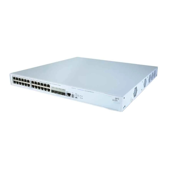
1: I 4500 F HAPTER NTRODUCING THE WITCH AMILY About the Switch The Switch 4500 Family are mixed media devices. Table 3 summarizes 4500 what each Switch consists of: Table 3 Switch 4500 Family Hardware Switch 4500 Family Switch 4500 26 Port Switch 4500 50 Port †... -
Page 15: Summary Of Hardware Features
Switch 4500 — Front View Detail Summary of Table 4 summarizes the hardware features that are supported by the Hardware Features Switch 4500. Table 4 Hardware Features Feature Switch 4500 Addresses Up to 8,000 supported Auto-negotiation Supported on all non-SFP ports Forwarding Modes Store and Forward Duplex Modes... - Page 16 1: I 4500 F HAPTER NTRODUCING THE WITCH AMILY Figure 2 Switch 4500 50-Port — front view Port Status LEDs Console Port Unit LED PWR LED 3CR17562-91 SuperStack 3 Switch 4500 50-Port Speed:Green = 100Mbps, Yellow = 10Mbps Duplex:Green = Full Duplex, Yellow = Half Duplex 51/49 52/50 RPS LED...
-
Page 17: 10Base-T/ 100Base-Tx Ports
Two 1000BASE-T SFP modules are inlcuded with these switches and can be used for uplinks or stacking using copper Ethernet cabling. While usable in any of the SFP ports, 3Com recommends these SFP modules be installed in the two right-most ports of the switches (27/28 or 51/52). -
Page 18: Unit Led
1: I 4500 F HAPTER NTRODUCING THE WITCH AMILY Unit LED The Unit LED is a seven segment display visible on the front of the Switch. The Unit LED can be used to indicate the unit number in a fabric, POST test ID and software upgrade information. - Page 19 Switch 4500 — Front View Detail Color Indicates RPS LED (3CR17571-91 and 3CR17572-91 only) Green AC and RPS supply connected. Yellow AC failed or not connected. RPS supply is OK. There is no RPS supply connected. 10BASE-T/100-TX Port LEDs Speed Green A high speed (100 Mbps) link is present, blinking off for every packet received or transmitted.
-
Page 20: Switch 4500 - Rear View Detail
1: I 4500 F HAPTER NTRODUCING THE WITCH AMILY Switch 4500 — Rear Figure 5 Switch 4500 — rear view View Detail Open Book Warning Labels Power Socket 100-240V; 50/60Hz; 1A Earthing Screw Figure 6 Switch 4500 PWR - rear view Open Book Warning Labels Power Socket NULL... -
Page 21: Redundant Power System Socket
Default Settings AVVERTENZA: Prima di installare o rimuovere qualsiasi componente dello Switch 4500 Family o di eseguire qualsiasi procedura di manutenzione, leggere le informazioni di sicurezza riportate nell'Appendice A di questa guida. OSTRZEŻENIE: Przed instalacją lub usunięciem jakichkolwiek elementów z przełącznika z rodziny 4500 lub przeprowadzeniem prac konserwacyjnych należy zapoznać... - Page 22 1: I 4500 F HAPTER NTRODUCING THE WITCH AMILY Feature Switch 4500 Traffic Prioritization All ports prioritize NBX VoIP traffic (LAN and IP). All ports set to “best effort” for all other traffic. Port Security Disabled per port Configuration Save and Disabled Restore...
-
Page 23: Installing The Switch
NSTALLING THE WITCH This chapter contains the information you need to install and set up the Switch 4500. It covers the following topics: Package Contents ■ Choosing a Suitable Site ■ Rack-mounting ■ Connecting a Redundant Power Supply to your Switch 4500 PWR ■... -
Page 24: Package Contents
2: I HAPTER NSTALLING THE WITCH AVVERTENZA: Informazioni di sicurezza. Prima di installare o rimuovere qualsiasi componente dal Switch 4500 o di eseguire qualsiasi procedura di manutenzione, leggere le informazioni di sicurezza riportate nell'Appendice A della presente guida per l'utente. OSTRZEŻENIE: Informacje o zabezpieczeniach. -
Page 25: Choosing A Suitable Site
■ Air flow is not restricted around the Switch or through the vents in the ■ side of the Switch. 3Com recommends that you provide a minimum of 25mm (1in.) clearance. Air temperature around the Switch does not exceed 40 (104 °C... -
Page 26: Rack-Mounting
2: I HAPTER NSTALLING THE WITCH Rack-mounting The Switch 4500 is 1U high and will fit in most standard 19-inch racks. CAUTION: Disconnect all cables from the Switch before continuing. Remove all self adhesive pads from the underside of the Switch if they have been fitted. -
Page 27: Rack Mounting The Back Of Your Switch 4500 (Pwr Only)
Rack-mounting Rack Mounting the To rack mount the back of your Switch 4500 (PWR only): Back of your Switch 4500 (PWR only) 1 Locate a rear rail bracket over the mounting holes on one side of the rear of the Switch, as shown in Figure 8. The bracket has two mounting positions depending on the rack depth. -
Page 28: Connecting A Redundant Power Supply To Your Switch 4500 Pwr
DC supply from the RPS. 3Com Switches which support -48V DC RPS inputs, that are PoE enabled, can only be powered by an RPS which complies with the isolation requirements of IEEE-Std 802.3af. - Page 29 Connecting a Redundant Power Supply to your Switch 4500 PWR WARNING: Any RPS must be approved as a SELV output in accordance with IEC 60950-1/UL 60950-1/EN 60950-1. WARNING: The characteristics of the Switch 4500 DC supply input are given in Appendix C on page 115. The Switch 4500 PWR units can be powered in three different ways: AC Mains only —...
-
Page 30: Specifying The Redundant Power System
-48V DC RPS that meets the requirements defined in Appendix C on System page 115. For an approved vendor list, more details about purchasing the 3Com recommended RPS and a full set of requirements go to: http://www.3Com.com/RPS The 3Com recommended RPS generates -48V DC power using power supply units (or rectifiers). -
Page 31: Connecting The Switch To The Redundant Power System
AC mains power. 3Com’s RPS solution uses -48V DC power distribution. The RPS system provides bulk -48V DC power that is separately distributed to a number of network switches. - Page 32 2: I HAPTER NSTALLING THE WITCH WARNING: Ensure that the circuit breaker in the RPS is in the open (off) position when connecting the cable to the RPS and the cable and connector to the Switch. WARNING: You must ensure that the positive terminal on the Switch is connected to the positive (common) terminal of the RPS and that the negative terminal on the Switch is connected to the negative (circuit breaker) terminal of the RPS.
-
Page 33: Connecting The Earthing Cable
Reduced Cabling — a PoE (802.3af) compliant device which has its ■ power supplied over its ethernet cable does not require a separate power supply. If, for example, the Switch is used to connect a 3Com 11 Mbps Wireless LAN Access Point 8500 to the network, then only a... -
Page 34: Placing Units On Top Of Each Other
The Switch 4500 supports 3Com 802.3af equipment. For the latest list of supported devices, refer to the product page on the 3Com web site at http://www.3com.com/ For further information on Power over Ethernet, refer to the Power over Ethernet Configuration chapter in the Configuration Guide supplied on the CD-ROM that accompanies your Switch 4500. -
Page 35: The Power-Up Sequence
The Power-up Sequence The Power-up The following sections describe how to get your Switch 4500 Sequence powered-up and ready for operation. Powering-up the Use the following sequence of steps to power-up the Switch. Switch 4500 1 Plug the power cord into the power socket at the rear of the Switch. 2 Plug the other end of the power cord into your power outlet. - Page 36 MDI port, you need to use a standard straight-through cable. See Table 13. 3Com recommends that you use at least Category 5 twisted pair cable — the maximum segment length for this type of cable is 100 m (328 ft.).
-
Page 37: Choosing The Correct Cables For The 1000Base-X Sfp Ports
The Power-up Sequence Choosing the Correct The 1000BASE-SX SFP transceiver supports a direct connection to a Cables for the multi-mode fiber-optic cable. The 1000BASE-LX SFP transceiver supports 1000BASE-X SFP Ports a direct connection to single-mode and multi-mode fiber-optic cables. The 1000BASE-LH70 SFP transceiver supports a direct connection to a single-mode fiber-optic cable and the 1000BASE-T SFP transceiver uses Category 5 copper cabling with RJ-45 connectors and supports segment lengths of up to 100 m (328 ft). -
Page 38: Sfp Operation
The 3CSFP93-4500 is approved for use in the Switch 4500 only. To access the latest list of approved SFP transceivers for the Switch on the 3Com Corporation World Wide Web site, enter this URL into your internet browser: http://www.3com.com/transceiver 1000BASE-SX, 1000BASE-LX, 1000BASE-LH70 or 1000BASE-T SFP... -
Page 39: Inserting An Sfp Transceiver
If the SFP transceiver is faulty, it will not operate within the Switch. See “Solving Hardware Problems” on page 69. 3Com recommends that you only use Gigabit Ethernet SFPs supplied by 3Com. If the SFP transceiver is invalid it will not be recognized by the Switch. Inserting an SFP... -
Page 40: Removing An Sfp Transceiver
Packing and This section describes how to correctly package your Switch 4500 should Shipping the Switch you need to return the Switch to 3Com. 4500 WARNING: The unit should be packaged safely to ensure that you do not invalidate the repair. -
Page 41: Setting U P For Management
ETTING P FOR ANAGEMENT To make full use of the features offered by your Switch, and to change and monitor the way it works, you have to access the management software that resides on the Switch. This is known as managing the Switch. -
Page 42: Methods Of Managing A Switch
3: S HAPTER ETTING P FOR ANAGEMENT Methods of To manage your Switch you can use one of the following methods: Managing a Switch Command line interface management ■ Command line interface management using SSH ■ Web interface management ■ SNMP management ■... -
Page 43: Command Line Interface Management Using Ssh
You can manage a Switch using any network management workstation running the Simple Network Management Protocol (SNMP) as shown in Figure 15. For example, you can use the 3Com Network Director software, available from the 3Com website. Figure 15 SNMP Management over the Network... -
Page 44: Setting Up Overview
How do you want to connect to the Switch? configured IP information? Connect to the con- Connect to a front panel port Use 3Com Network Connect to the console sole port and use the and use the Web Interface or Director (3ND). -
Page 45: Ip Configuration
(Static IP addresses are necessary to ensure that the Switch is always allocated the same IP information.) For most installations, 3Com recommends that you configure the Switch IP information manually. This makes management simpler and more reliable as it is not dependent on a DHCP server, and eliminates the risk of the IP address changing. -
Page 46: Preparing For Management
For a detailed description of how automatic IP configuration operates, please refer to the Configuration Guide on the CD-ROM that accompanies your Switch or the 3Com Web Site. You should use the automatic IP configuration method if: your network uses DHCP to allocate IP information, or ■... -
Page 47: Manually Configuring Ip Information
Manually Configuring IP Information Manually You can manually configure the Switch IP information in the following Configuring IP ways: Information Connecting to the console port — connect a workstation using a ■ console cable to the console port of the Switch. You can then manually enter IP information using the command line interface (CLI). - Page 48 3: S HAPTER ETTING P FOR ANAGEMENT Connecting the Workstation to the Switch 1 Connect the workstation to the console port using the console cable as shown in Figure 17. Figure 17 Connecting a Workstation to the Switch via the Console Port Workstation Switch (with terminal emulation...
- Page 49 Manually Configuring IP Information 2 At the login and password prompts, enter as your user name and admin press Return and at the password prompt press Return again. If you have logged on correctly, <4500> should be displayed as shown in Figure 18. Once you have logged in you will automatically be in User View.
-
Page 50: Connecting To A Front Panel Port
3: S HAPTER ETTING P FOR ANAGEMENT If you do not intend to use the command line interface via the console port to manage the Switch, you can disconnect the serial cable and close the terminal emulator software. Connecting to a Front To set up your Switch manually you can, alternatively, make a connection Panel Port to a front panel port. - Page 51 Manually Configuring IP Information Connecting the Workstation to the Switch 1 Connect the workstation to a front panel port using an Ethernet cable as shown in Figure 19. Figure 19 Connecting a Workstation to the Switch via a Front Panel Port Switch Workstation (with a Network...
- Page 52 3: S HAPTER ETTING P FOR ANAGEMENT 4 To enter basic setup information for the Switch, select Administration > IP Setup and then follow the wizard through various system screens to enter the IP address and subnet mask that you want the Switch to use when it is connected to the network.
-
Page 53: Viewing Automatically Configured Ip Information
IP information before you can begin to Configured IP manage the Switch. You can discover the IP information in two ways: Information Using 3Com Network Director — this application will auto-discover ■ the Switch and display the automatically allocated IP information assigned to the Switch. -
Page 54: Using 3Com Network Director
DHCP or BootP server. If your network does not have a DHCP or BootP server, the workstation running 3Com Network Director must be on the same subnet as the Switch, because Auto-IP addresses are non-routable. Connecting to the... - Page 55 Viewing Automatically Configured IP Information If the login prompt does not begin immediately, press Return a few times until it starts. 3 At the login and password prompts, enter as your user name and admin press Return at the password prompt. If you have logged on correctly, <4500>...
-
Page 56: Setting Up Command Line Interface Management
3: S HAPTER ETTING P FOR ANAGEMENT Setting Up This section describes how you can set up command line interface Command Line management using a local console port connection or over the network. Interface Management User Interface User interface configuration is provided by the Switch to configure and Overview manage the port data. -
Page 57: Setting Up Command Line Interface Management Using Ssh
SSH connections to the switch will be refused. 4 Install an SSH client application on the workstation you want to use to access the switch. 3Com recommends the following SSH clients; PuTTY, OpenSSH and SSH Communications Security Corp Secure Shell. -
Page 58: Setting Up Web Interface Management
3: S HAPTER ETTING P FOR ANAGEMENT 5 Open an SSH session and access the Switch using the Switch’s IP address and port number. The first time you connect to the switch the client will ask you to confirm that the host key is correct for the device. 6 The Switch and the SSH client will authenticate each other and a secure connection will be established. -
Page 59: Web Management Over The Network
VLAN 1 (the Default VLAN). By default, all ports on the Switch are in VLAN 1. You can use the 3Com Network Director application that is available from the 3Com website to provide SNMP management for your Switch. If you use 3Com Network Director it automatically loads the correct MIBs and necessary files onto your workstation. -
Page 60: Pre-Requisites
3: S HAPTER ETTING P FOR ANAGEMENT Pre-requisites Documentation supplied with the SNMP network management ■ application software. The default read community string is public. To change this setting in System View, enter display snmp community. The default write community string is private. To change this setting in System View, enter display snmp community. - Page 61 Default Users and Passwords Use the admin default user name (no password) to login and carry out initial Switch setup. To set a password for the admin user in the CLI, enter the following from system view: [4500]local-user admin <cr> [4500-luser-admin]password simple xxxxxxxx (where xxxxxxxx is your chosen password).
- Page 62 3: S HAPTER ETTING P FOR ANAGEMENT...
-
Page 63: Creating A Stack
Unit Numbering within the Stack ■ How To Up to eight 3Com Switch 4500 units can be interconnected to create a Interconnect Units stack and then treated as a single manageable unit with one IP address. You can interconnect your Switches to create a stack using a standard 1000 Mbps Ethernet connection. -
Page 64: Guidelines For Interconnecting Units
The maximum number of Switch units that can be interconnected is ■ eight. You can only create a stack by interconnecting a 3Com Switch 4500 ■ with other 3Com Switch 4500s. Stacking is only supported using Gigabit ports. -
Page 65: Unit Numbering Within The Stack
Switch with the lowest MAC address assumes the ID in question and the other unit will automatically renumber. 3Com recommends that you manually assign the unit IDs within the stack if you wish to have predictability of knowing which units have which IDs at all times. - Page 66 4: C HAPTER REATING A TACK Renumbering only occurs when the stack is next power cycled if the units are configured to auto-number. The unit LEDs will display the unit number in the stack, from 1 to 8. If you are having problems, refer to “Solving Stack Formation Problems” on page 73.
-
Page 67: Problem Solving
ROBLEM OLVING This chapter helps you to diagnose and solve problems you may have with the operation of your Switch. There is also an explanation of IP addressing and upgrading software. The topics covered are: Solving Problems Indicated by LEDs ■... -
Page 68: Solving Problems Indicated By Leds
5: P HAPTER ROBLEM OLVING Solving Problems If the LEDs on the Switch indicate a problem, refer to the list of suggested Indicated by LEDs solutions below. The PWR LED does not light Check that the power cable is firmly connected to the Switch and to the supply outlet. -
Page 69: Solving Hardware Problems
Solving Hardware Problems Auto-negotiation problems will occur with 10BASE-T or 100BASE-T where auto-negotiation is disabled and incorrect cables are being used (cross-over or straight) Auto-negotiation problems will occur with fiber if: The Receiver (RX) and Transceiver (TX) cable connectors are ■... - Page 70 RPS supply. 4 If another fan failure warning message is generated via the Command Line Interface or the Web interface, return the unit to 3Com. Unit fails, no SNMP fan failure message is received 1 Power cycle the unit. To do this, remove and reconnect the AC mains supply.
-
Page 71: Solving Communication Problems
IP address of the router. The Switch’s IP address has been entered correctly in your network ■ management application (such as 3Com Network Director). The following is a brief overview of IP addressing, and how to obtain a registered IP address. - Page 72 If your IP network is internal to your organization only, that is, you do not access the Internet, you may use any arbitrary IP address as long as it is not being used by another device on your network. 3Com suggests you use addresses in the range 192.168.0.0 to 192.168.255.255 with a subnet mask of 255.255.255.0.
-
Page 73: Solving Stack Formation Problems
Solving Stack Formation Problems Solving Stack If you are having problems with correctly forming a stack, first ensure that Formation Spanning Tree is enabled. If it is enabled, do the following: Problems 1 Power off all units in the stack. 2 Check all the cable connections in the stack. - Page 74 5: P HAPTER ROBLEM OLVING...
-
Page 75: Upgrading Software
PGRADING OFTWARE This chapter describes how to upgrade software to your Switch 4500. It covers the following topics: The Contents of the Executable File ■ Upgrading from the Command Line Interface ■ Upgrading from the Bootrom Interface ■ Bootrom Upgrade ■... -
Page 76: The Contents Of The Executable File
Bundled files with the extension NetMan.zip, can be used to upgrade your Switch using the 3Com Network Director Agent Update. Any attempt to upgrade individual .web, .btm or .app files using 3Com Network Director will fail. These files should be used to upgrade your Switch as described below. - Page 77 Upgrading from the Command Line Interface A file list similar to the following is displayed: Directory of unit1>flash:/ -rw- 714784 Apr 02 2005 01:36:16 s3p03_01_00.zip -rw- 11043 Apr 02 2005 01:37:17 3ComOScfg.def -rw- 11427 Apr 02 2005 00:01:01 3ComOScfg.cfg -rw- 4529259 Apr 02 2005 01:39:57 s3n03_01_00s168.app 15367 KB total (10215 KB free)
-
Page 78: Backup
6: U HAPTER PGRADING OFTWARE To check that deleted files have been removed from the recycle-bin for the remaining units in a fabric, replace unit1 with unit2 and so on for each Switch in the fabric. Backup The following steps enable you to backup each Switch in the fabric: 1 To back up the default configuration file on each Switch in the fabric, enter: copy unit1>flash:/3ComOScfg.def... - Page 79 Upgrading from the Command Line Interface 3 To download the default configuration file, enter: tftp aaa.aaa.aaa.aaa get 3ComOScfg.def 4 To download the bootrom file, enter: tftp aaa.aaa.aaa.aaa get s3o002_012_000.btm The bootrom firmware may not require upgrading for every software upgrade, therefore there may not be a new bootrom (.btm) file to download.
-
Page 80: Ftp
6: U HAPTER PGRADING OFTWARE To set the remaining Switches in the fabric to boot from the new software, replace unit1 with unit2 and so on for each Switch in the fabric. 2 To set the Switch to load the new bootrom firmware, enter: boot bootrom unit1>flash:/s3o002_012_000.btm To set the remaining Switches in the fabric to load the new bootrom firmware, replace unit1 with unit2 and so on for each Switch in the... -
Page 81: Xmodem (Via The Console Cable)
Upgrading from the Command Line Interface 200 PORT command successful. 150 Opening ASCII mode data connection for vrpcfg.def(10986 bytes)..226 Transfer complete. FTP: 10986 byte(s) received in 8.046 second(s) 1000.00 byte(s)/sec. 3 Enter quit to exit. XModem (via the To upgrade software to your Switch via XModem do the following: console cable) 1 From the User View, enter: xmodem get unit1>flash:/3ComOScfg.def... -
Page 82: Upgrading From The Bootrom Interface
6: U HAPTER PGRADING OFTWARE Upgrading from the This section describes how to upgrade your Switch from the Bootrom Bootrom Interface Interface. Introduction When the Switch is running the initial boot phase via the console, the following prompt is displayed with a five second countdown timer: Press CTRL-B to enter Boot Menu... - Page 83 Upgrading from the Bootrom Interface 3 Select option 3 from the Boot Menu. A file list similar to the following is displayed: Boot menu choice: 3 File Number File Size(bytes) File Name ==================================================== snmpboots private-data.txt 3(*) 4649088 s3n03_01_00s168.app 576218 s3p03_01_03_0024.zip 10301 3comoscfg.def 10369...
-
Page 84: Tftp
6: U HAPTER PGRADING OFTWARE TFTP To upgrade software to your Switch via TFTP, do the following: 1 From the Boot Menu, select option 1 (Download application file to flash) to display the following: 1. Set TFTP protocol parameter 2. Set FTP protocol parameter 3. -
Page 85: Xmodem
Upgrading from the Bootrom Interface Server IP address: FTP User Name: FTP User Password: 3 Enter the file name, Switch IP address, Server IP address and FTP user name and password to display the following: Are you sure to download file to flash? Yes or No(Y/N) 4 Enter y and the following information is displayed to indicate the file is downloading: Loading..done... -
Page 86: Bootrom Upgrade
6: U HAPTER PGRADING OFTWARE Now please start transfer file with XMODEM protocol If you want to exit, Press <Ctrl+X> Loading...CCCCCCCCCCCCCCCCCCCCCCCCCCCCC 5 As the file is downloading, start the XModem send file process with terminal emulation software, such as Microsoft Hyperterminal. When the download is complete, the following information is displayed: Please input the file attribute (main/backup/none):none done! -
Page 87: Bootrom Upgrade Via Tftp
Bootrom Upgrade Bootrom Upgrade To upgrade the bootrom firmware from the Boot menu via TFTP do the via TFTP following: 1 From the Boot menu, select option 6 to display the bootrom upgrade menu as shown: Bootrom update menu: 1. Set TFTP protocol parameter 2. -
Page 88: Bootrom Upgrade Via Xmodem
6: U HAPTER PGRADING OFTWARE Load File name: Switch IP address: Server IP address: FTP User Name: FTP User Password: 3 Enter the file name, Switch IP address, Server IP address, FTP user name and password to display the following: Are you sure to update your bootrom? Yes or No(Y/N) 4 Enter y and the following information is displayed to indicate the file is downloading:... - Page 89 Bootrom Upgrade 4 Press Enter to start the download. The following information is displayed: Now please start transfer file with XMODEM protocol If you want to exit, Press <Ctrl+X> Loading ...CCCCCCCCCCCCCCCCCCCCCCCCCCCCC 5 As the file is downloading, start the XModem send file process with terminal emulation software, such as Microsoft Hyperterminal.
- Page 90 6: U HAPTER PGRADING OFTWARE...
-
Page 91: Safety Information
AFETY NFORMATION You must read the following safety information before carrying out any installation or removal of components, or any maintenance procedures on the Switch 4500. WARNING: Warnings contain directions that you must follow for your personal safety. Follow all directions carefully. You must read the following safety information carefully before you install or remove the unit. -
Page 92: Power Cord Set - Japan
A: S PPENDIX AFETY NFORMATION AVVERTENZA: le avvertenze contengono istruzioni indispensabili per assicurare la sicurezza personale. Seguire attentamente tutte le indicazioni fornite. Prima di installare o rimuovere l'unità, leggere attentamente le seguenti informazioni di sicurezza. OSTRZEŻENIE: Ostrzeżenia zawierają wskazówki, których należy przestrzegać... - Page 93 Important Safety Information U.S.A. and The cord set must be UL-approved and CSA certified. ■ Canada The minimum specification for the flexible cord is: ■ No. 18 AWG Type SV or SJ 3-conductor The cord set must have a rated current capacity of at least ■...
- Page 94 A: S PPENDIX AFETY NFORMATION WARNING: U.K. only: If connecting a modem to the console port of the Switch 4500, only use a modem which is suitable for connection to the telecommunications system. WARNING: RJ-45 Ports. These are shielded RJ-45 data sockets. They cannot be used as standard traditional telephone sockets, or to connect the unit to a traditional PBX or public telephone network.
-
Page 95: L'information De Sécurité Importante
L’information de Sécurité Importante WARNING: The characteristics of the Switch 4500 DC supply input are given in Appendix C on page 115. WARNING: RPS Manufacturers recommendations must be followed when connecting the cable to the RPS. WARNING: Ensure that the circuit breaker in the RPS is in the open (off) position when connecting the cable to the RPS and the cable and connector to the Switch. - Page 96 A: S PPENDIX AFETY NFORMATION AVERTISSEMENT: Cordon électrique: Il doit être agréé ans le pays d'utilisation: Etats-Unis et Le cordon doit avoir reçu l'homologation des UL et un ■ Canada certificat de la CSA Le cordon souple doit respecter, à titre minimum, les ■...
- Page 97 L’information de Sécurité Importante AVERTISSEMENT: Points d’accès RJ-45. Ceux-ci sont protégés par des prises de données. Ils ne peuvent pas être utilisés comme prises de téléphone conventionnelles standard, ni pour la connection de l’unité à un réseau téléphonique central privé ou public. Raccorder seulement connecteurs de données RJ-45, systèmes de réseaux de téléphonie ou téléphones de réseaux à...
- Page 98 A: S PPENDIX AFETY NFORMATION AVERTISSEMENT: Le RPS doit être approuvé en tant que sortie SELV non reliée à la terre, conformément à la norme IEC 60950-1/UL 60950-1/EN 60950-1. AVERTISSEMENT: Ces instructions doivent être lues conjointement avec les caractéristiques de l'alimentation CC du Switch 4500 fournies en annexe C, Spécifications techniques.
-
Page 99: Wichtige Sicherheitsinformationen
Wichtige Sicherheitsinformationen Wichtige Sicherheitsinformationen VORSICHT: Alle Verfahren die in dieser Anleitung beschrieben werden gelten für alle Modelle, sofern nicht anders angegeben. Wo eine Vorgehensweise für die Schalter 4500 26 und Schalter 4500 50 gilt wird nur der Begriff Schalter verwendet. Diese Anleitung ist für Netzwerkadministratoren vorgesehen, die für die Installation und das Einstellen von Netzwerkkomponenten verantwortlich sind;... - Page 100 A: S PPENDIX AFETY NFORMATION VORSICHT: Der Betrieb dieses Geräts erfolgt unter den SELV-Bedingungen (Sicherheitskleinstspannung) gemäß IEC 60950. Diese Bedingungen sind nur gegeben, wenn auch die an das Gerät angeschlossenen Geräte unter SELV-Bedingungen betrieben werden. VORSICHT: RJ-45-Porte. Diese Porte sind geschützte Datensteckdosen. Sie dürfen weder wie normale traditionelle Telefonsteckdosen noch für die Verbindung der Einheit mit einem traditionellem privatem oder öffentlichem Telefonnetzwerk gebraucht werden.
- Page 101 Wichtige Sicherheitsinformationen verbunden werden oder beides. Es ist sicherzustellen, dass die Erdungsverbindung vor dem Anschließen der von der RPS bereitgestellten Gleichstromversorgung hergestellt wird. VORSICHT: Jede RPS muss als nicht geerdetes SELV-Ausgangsgerät gemäß IEC 60950-1/UL 60950-1/EN 60950-1 zugelassen sein. VORSICHT: Diese Anleitungen müssen im Zusammenhang mit den Eigenschaften des Gleichstrom-Versorgungseingangs des Switch 4500 gelesen werden, die in Anhang C, "Technische Daten", aufgeführt sind.
-
Page 102: Información De Seguridad Importante
A: S PPENDIX AFETY NFORMATION Información de Seguridad Importante ADVERTENCIA: La instalación o la extracción de la unidad sólo debe llevarla a cabo personal cualificado. ADVERTENCIA: Si instala el 4500 en una pila con unidades SuperStack II o SuperStack 3 que son más estrechas que el 4500, la unidad 4500 debe instalarse debajo de las unidades más estrechas. - Page 103 Información de Seguridad Importante ADVERTENCIA: El acoplador del equipo (el conector para la unidad y no la toma de la pared) debe tener una configuración que se adapte a una entrada del equipo EN60320/IEC320. ADVERTENCIA: El enchufe debe estar cerca de la unidad y ser de fácil acceso.
- Page 104 A: S PPENDIX AFETY NFORMATION ADVERTENCIA: Este dispositivo dispone de más de una entrada de alimentación. Desconecte todas las entradas de alimentación del dispositivo. ADVERTENCIA: La instalación del sistema de alimentación superflua (RPS) sólo debería llevarla a cabo personal cualificado y con la debida formación.
-
Page 105: Importanti Informazioni Di Sicurezza
Importanti Informazioni di Sicurezza Importanti Informazioni di Sicurezza AVVERTENZA: Le operazioni di installazione e rimozione dell'unità devono essere eseguite esclusivamente da personale qualificato. AVVERTENZA: Se si installa lo 4500 in uno stack con unità SuperStack II o SuperStack 3 più strette del modello 4500, posizionare lo 4500 sotto tali unità. - Page 106 A: S PPENDIX AFETY NFORMATION AVVERTENZA: L'accoppiatore (il connettore all'unità e non la spina a muro) deve avere una configurazione abbinabile a una presa EN60320/IEC320. AVVERTENZA: La presa deve trovarsi vicino all'unità ed essere facilmente accessibile. AVVERTENZA: Questa unità funziona alle condizioni SELV (Safety Extra Low Voltage) previste dalla norma IEC 60950.
- Page 107 Importanti Informazioni di Sicurezza AVVERTENZA: Il dispositivo presenta più punti di alimentazione. Per spegnere il dispositivo, scollegare tutti i punti di alimentazione. AVVERTENZA: le operazioni di installazione dell'RPS (Redundant Power Supply) devono essere eseguite esclusivamente da personale qualificato e opportunamente addestrato. AVVERTENZA: queste istruzioni devono essere lette insieme alle istruzioni di sicurezza e installazione fornite con l'RPS.
-
Page 108: Wa¿Ne Informacje O Zabezpieczeniach
A: S PPENDIX AFETY NFORMATION Ważne informacje o zabezpieczeniach OSTRZEŻENIE: Instalacja i demontaż urządzenia mogą być wykonywane tylko przez wykwalifikowany personel. OSTRZEŻENIE: Podczas instalacji Switch 4500 w stosie z urządzeniami SuperStack II lub SuperStack 3, które są węższe niż Switch 4500, urządzenie Switch 4500 musi być... - Page 109 Wa¿ne informacje o zabezpieczeniach OSTRZEŻENIE: Złączka urządzenia (podłączona do przełącznika, a nie do wtyczki ściennej) musi być odpowiednio dopasowana do normy EN60320/IEC320 otworu wlotowego. OSTRZEŻENIE: Gniazdo zasilające musi być umieszczone w pobliżu urządzenia i musi być łatwo dostępne. OSTRZEŻENIE: Urządzenie to pracuje w warunkach SELV (Safety Extra Low Voltage –...
- Page 110 A: S PPENDIX AFETY NFORMATION OSTRZEŻENIE: To urządzenie ma kilka punktów podłączenia zasilania. Aby wyłączyć urządzenie, należy odłączyć wszystkie punkty zasilania. OSTRZEŻENIE: Instalacja zasilacza nadmiarowego (RPS) powinna być wykonywana przez odpowiednio przeszkolony i wykwalifikowany person- OSTRZEŻENIE: Te instrukcje należy przeczytać razem z instrukcjami dotyczącymi bezpieczeństwa i instalacji dostarczonymi z systemem zasi- lania nadmiarowego.
-
Page 111: In Outs
OUTS Null Modem Cable RJ-45 to RS-232 25-pin Switch 4500 PC/Terminal Cable connector: RJ-45 female Cable connector: 25-pin male/female only required if screen Screen Shell Screen always required Ground Ground required for handshake PC-AT Serial Cable RJ-45 to 9-pin Switch 4500 PC-AT Serial Port Cable connector: RJ-45 female Cable connector: 9-pin female... -
Page 112: Modem Cable
B: P PPENDIX OUTS Modem Cable RJ-45 to RS-232 25-pin Switch 4500 RS-232 Modem Port Cable connector: RJ-45 female Cable connector: 25-pin male Screen Shell Screen Ground Ground Ethernet Port RJ-45 10/100 and 1000BASE-T RJ-45 connections. Pin Assignments Table 10 Pin assignments Pin Number 10/100 1000... - Page 113 Ethernet Port RJ-45 Pin Assignments Table 11 Pin assignments Pin Number 10/100 1000 Ports configured as MDIX Receive Data + Bidirectional Data B+ Receive Data - Bidirectional Data B- Transmit Data + Bidirectional Data A+ Not assigned Bidirectional Data A- Not assigned Bidirectional Data D+ Transmit Data –...
- Page 114 B: P PPENDIX OUTS...
-
Page 115: Specifications
–10 ° to +70 °C (14 ° to 158 °F) Operating Humidity 95% non-condensing Standards EN60068 to 3Com schedule (Package testing: paras 2.1, 2.2, 2.30, and 2.32. Operational testing: paras 2.1, 2.2, 2.30 and 2.13). Safety Agency Certifications UL 60950, EN60950, CSA 22.2 No. 60950, IEC 60950... -
Page 116: Switch 4500 (50 Port)
–10 ° to +70 °C (14 ° to 158 °F) Operating Humidity 95% non-condensing Standards EN60068 to 3Com schedule (Package testing: paras 2.1, 2.2, 2.30, and 2.32. Operational testing: paras 2.1, 2.2, 2.30 and 2.13). Safety Agency Certifications UL60950, EN60950, CSA 22.2 No. 60950, IEC 60950... -
Page 117: Switch 4500 Pwr (26 Port)
–10 ° to +70 °C (14 ° to 158 °F) Operating Humidity 95% non-condensing Standards EN60068 to 3Com schedule (Package testing: paras 2.1, 2.2, 2.30, and 2.32. Operational testing: paras 2.1, 2.2, 2.30 and 2.13). Safety Agency Certifications UL60950, EN60950, CSA 22.2 No. 60950, IEC 60950... -
Page 118: Switch 4500 Pwr (50 Port)
–10 ° to +70 °C (14 ° to 158 °F) Operating Humidity 95% non-condensing Standards EN60068 to 3Com schedule (Package testing: paras 2.1, 2.2, 2.30, and 2.32. Operational testing: paras 2.1, 2.2, 2.30 and 2.13). Safety Agency Certifications UL60950, EN60950, CSA 22.2 No. 60950, IEC 60950... -
Page 119: Rps
Standards Supported SNMP Terminal Emulation SNMP protocol (RFC 1157) Telnet (RFC 854) MIB-II (RFC 1213) Protocols Used for Administration Bridge MIB (RFC 1493) UDP (RFC 768) RMON MIB II (RFC 2021) IP (RFC 791) Remote Monitoring MIB (RFC ICMP (RFC 792) 1757) TCP (RFC 793) MAU MIB (RFC 2239) - Page 120 C: T PPENDIX ECHNICAL PECIFICATIONS...
-
Page 121: Register Your Product
More information on 3Com maintenance and Professional Services is available at http://www.3com.com/ Contact your authorized 3Com reseller or 3Com for a complete list of the value-added services available in your area. -
Page 122: Troubleshoot Online
PPENDIX BTAINING UPPORT FOR YOUR RODUCT Troubleshoot You will find support tools posted on the 3Com web site at Online http://www.3com.com/ 3Com Knowledgebase helps you troubleshoot 3Com products. This query-based interactive tool is located at and contains thousands of technical http://knowledgebase.3com.com... -
Page 123: Contact Us
Contact Us To send a product directly to 3Com for repair, you must first obtain a return authorization number (RMA). Products sent to 3Com, without authorization numbers clearly marked on the outside of the package, will be returned to the sender unopened, at the sender’s expense. If your... - Page 124 You can also obtain support in this region using the following URL: http://emea.3com.com/support/email.html Latin America Telephone Technical Support and Repair Antigua 1 800 988 2112 Guatemala AT&T +800 998 2112 Argentina 0 810 444 3COM Haiti 57 1 657 0888 Aruba 1 800 998 2112 Honduras AT&T +800 998 2112 Bahamas...
- Page 125 Switch 23 prerequisites 25 IP addressing registered 71 IP configuration 45 access levels of default users 60 automatic setup 53 3Com Network Director 54 console port 54 LEDs 18 logging in as a default user 60 browsers choosing 58 management...
- Page 126 NDEX rack mounting a Switch 4500 26 upgrading software redundant power supply (RPS) 28 bootrom 82 related documentation 11 bootrom via FTP 87 RPS connection 35 bootrom via TFTP 87 bootrom via XModem 88 file distribution 79 FTP 80, 84 safety information TFTP 78, 84 English 92...
- Page 127 EGULATORY OTICES FCC S TATEMENT This equipment has been tested and found to comply with the limits for a Class A digital device, pursuant to part 15 of the FCC rules. These limits are designed to provide reasonable protection against harmful interference when the equipment is operated in a commercial environment.