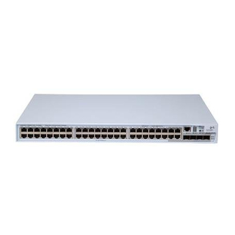
3Com 4200G Installation Manual
Switch 4200g 10g interface module
Hide thumbs
Also See for 4200G:
- Getting started manual (90 pages) ,
- Datasheet (8 pages) ,
- Quick reference manual (43 pages)
Advertisement
Quick Links
1. XFP Interface Module
1.1 Appearance and front panel
Figure 1 Appearance of an XFP interface module
Figure 2 Front panel an XFP interface module
1.2 Installation
Step 1: Put on an ESD-preventive wrist strap and verify it is properly
grounded. Then remove the XFP interface module from the package.
Step 2: Loosen the filler panel mounting screws on the rear panel of the
switch with a screwdriver and remove the filler panel.
Step 3: Hold the fastening screws on the front panel of the XFP interface
module, and gently push the module in along the slot guide rail until the
module is in close contact with the switch.
Step 4: Tighten the fastening screws with a screwdriver to secure the XFP
interface module.
3Com Switch 4200G
10G Interface Module
Installation Guide
1
Advertisement

Related Manuals for 3Com 4200G


Summary of Contents for 3Com 4200G
-
Page 1: Installation Guide
Step 4: Tighten the fastening screws with a screwdriver to secure the XFP interface module. 3Com Switch 4200G 10G Interface Module Installation Guide... - Page 2 (1): Switch (3): XFP interface module Figure 3 Installing an XFP interface module Note: (1) Store the filler panel for future use. (2) When tightening the fastening screws at both sides of the optional module with a screwdriver or an electric screwdriver, make sure that the torque is not bigger than 0.4 N-m.
-
Page 3: Xenpak Optical Module
2. XENPAK Optical Module 2.1 Appearance and front panel Figure 4 Appearance of a XENPAK optical module Figure 5 Front panel of a XENPAK optical module 2.2 Installation Step 1: Put on an ESD-preventive wrist strap and verify it is properly grounded. - Page 4 Figure 6 Installing a XENPAK optical module Note: (1) Retain the small cover plate for future use. (2) Do not tighten the module screws more than 0.4 Nm. (3) The switch 4200G supports hot swapping of XENPAK optical modules. 2.3 Removal Step 1: Put on an ESD-preventive wrist strap and verify it is properly grounded.