3Com 3C17203 Getting Started Manual
Superstack 3 switch 4400
Hide thumbs
Also See for 3C17203:
- Implementation manual (153 pages) ,
- Getting started manual (100 pages) ,
- Datasheet (8 pages)

Related Manuals for 3Com 3C17203


Summary of Contents for 3Com 3C17203
- Page 1 SuperStack Switch 4400 Getting Started Guide 3C17203 3C17204 3C17206 http://www.3com.com/ Part No. DUA1720-3AAA03 Published March 2002 ®...
- Page 2 All other company and product names may be trademarks of the respective companies with which they are associated. ENVIRONMENTAL STATEMENT It is the policy of 3Com Corporation to be environmentally-friendly in all operations. To uphold our policy, we are committed to: Establishing environmental performance standards that comply with national legislation and regulations.
-
Page 3: Table Of Contents
ONTENTS BOUT UIDE Conventions Related Documentation Accessing Online Documentation Product Registration Documentation Comments NTRODUCING THE UPER TACK WITCH About the Switch 4400 Summary of Hardware Features Summary of Software Features Switch 4400 — Front View Detail 10BASE-T/ 100BASE-TX Ports LEDs Switch 4400 —... - Page 4 Initial Switch Setup Manual Setup Connecting to a Front Panel Port Connecting to the Console Port Automatic Setup Using 3Com Network Supervisor Connecting to the Console Port Methods of Managing a Switch Command Line Interface Management Web Interface Management SNMP Management...
- Page 5 RJ-45 Pin Assignments ECHNICAL PECIFICATIONS Switch 4400 (24-port) Switch 4400 (48-port) ECHNICAL UPPORT Online Technical Services World Wide Web Site 3Com Knowledgebase Web Services 3Com FTP Site Support from Your Network Supplier Support from 3Com Returning Products for Repair NDEX EGULATORY OTICES...
-
Page 7: About This Guide
Most user guides and release notes are available in Adobe Acrobat Reader Portable Document Format (PDF) or HTML on the 3Com World Wide Web site: http://www.3com.com/... -
Page 8: Conventions
BOUT UIDE Conventions Table 1 Table 1 Notice Icons Table 2 Text Conventions Convention Screen displays This typeface represents information as it appears on the Syntax Commands The words “enter” and “type” Keyboard key names If you must press two or more keys simultaneously, the key Words in italics Table 2 list conventions that are used throughout this guide. -
Page 9: Related Documentation
Documentation accompanying the Advanced Redundant Power system. Documentation accompanying the Expansion Modules. Documentation accompanying 3Com Network Supervisor. This is supplied on the CD-ROM that accompanies the Switch. SuperStack 3 Switch Implementation Guide (PDF format) SuperStack 3 Switch Management Interface Reference Guide (HTML format). -
Page 10: Product Registration
■ 3Com recommends that you copy the Docs/reference directory as a whole to maintain the structure of the files. Product You can register your SuperStack 3 Switch 4400 on the 3Com Web site: Registration http://support.3com.com/registration/frontpg.pl Documentation Your suggestions are very important to us. They will help make our Comments documentation more useful to you. -
Page 11: Introducing The Super
NTRODUCING THE UPER This chapter contains introductory information about the Switch 4400 and how it can be used in your network. It covers summaries of hardware and software features and also the following topics: About the Switch 4400 ■ Switch 4400 — Front View Detail ■... -
Page 12: About The Switch 4400
1: I HAPTER NTRODUCING THE About the Switch The Switch 4400 is a stackable 10/100 Mbps device and provides 4400 high-performance work groups with a backbone to server connection. The Switch 4400 allows Cascade, Gigabit Ethernet or Fast Ethernet Fiber connections when expansion modules are installed in the expansion slots on the rear of the unit. -
Page 13: Summary Of Software Features
Summary of Software Table 4 Features Switch 4400. Table 4 Software features *Webcache support and Quality of Service (QoS) are not available on the SuperStack 3 Switch 4400 SE unless the product has been upgraded to the 4400 enhanced feature set. For information about managing the software features of the Switch, refer to the “SuperStack 3 Switch Management Interface Reference Guide”... -
Page 14: Switch 4400 - Front View Detail
1: I HAPTER NTRODUCING THE Switch 4400 — Figure 1 Switch 4400 / 4400 SE — front view 1 Front View Detail Figure 2 Switch 4400 / 4400 SE — front view 2 The appearance of the overlays in Figure 1 and Figure 2 differ but the functionality is identical for both Switches. -
Page 15: 10Base-T/ 100Base-Tx Ports
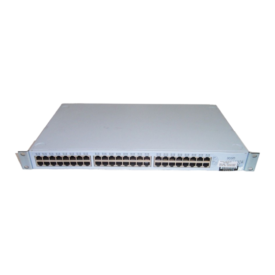
Switch 4400 — Front View Detail Figure 3 Switch 4400 (48-port) — front view WARNING: RJ-45 Ports. These are shielded RJ-45 data sockets. They cannot be used as standard traditional telephone sockets, or to connect the unit to a traditional PBX or public telephone network. Only connect RJ-45 data connectors, network telephony systems, or network telephones to these sockets. - Page 16 1: I HAPTER NTRODUCING THE Table 5 LED behavior Port Status LEDs Packet Green Status Green Module Packet LEDs Module Status LEDs Unit LEDs 1–8 4400 UPER TACK WITCH Color Indicates Full duplex packets are being transmitted/received on the port. Yellow Half duplex packets are being transmitted/received on the port.
-
Page 17: Switch 4400 - Rear View Detail
Power/Self Test LED Switch 4400 — Rear Figure 4 Switch 4400 / 4400 SE — rear view 1 View Detail Color Indicates Green rotating When a software upgrade is in progress, the Unit LEDs of the unit that is being upgraded flash on and off in the following sequence —... -
Page 18: Power Socket
1: I 4400 HAPTER NTRODUCING THE UPER TACK WITCH Figure 5 Switch 4400 / 4400 SE — rear view 2 The appearance of the Switches shown in Figure 1 and Figure 2 differ but the functionality is identical for both Switches. Power Socket The Switch automatically adjusts its power setting to any supply voltage in the range 90-260 VAC. -
Page 19: Default Settings
Default Settings Table 6 Table 6 Default Settings Webcache support and Quality of Service (QoS) are not available on the SuperStack 3 Switch 4400 SE unless the product has been upgraded to the 4400 enhanced feature set. If you initialize a Switch unit by selecting System > Control > Initialize in the Web interface or by entering system control initialize in the Command Line Interface, the following settings are retained to allow you to connect to and manage the Switch:... - Page 20 1: I 4400 HAPTER NTRODUCING THE UPER TACK WITCH...
-
Page 21: Installing The Switch
NSTALLING THE This chapter contains the information you need to install and set up the Switch 4400. It covers the following topics: Package Contents ■ Choosing a Suitable Site ■ Rack-mounting ■ Placing Units On Top of Each Other ■ The Power-up Sequence ■... -
Page 22: Package Contents
Water or moisture cannot enter the case of the Switch. Air-flow is not restricted around the Switch or through the vents in the side of the Switch. 3Com recommends that you provide a minimum of 25mm (1in.) clearance. Air flow around the Switch does not exceed 40 (104 °C... -
Page 23: Rack-Mounting
■ ■ ■ ■ ■ Rack-mounting The Switch 4400 is 1U high and will fit in most standard 19-inch racks. CAUTION: Disconnect all cables from the Switch before continuing. Remove all self adhesive pads from the underside of the Switch if they have been fitted. - Page 24 (not provided). Ensure that ventilation holes are not obstructed. position. The unit information label shows the following: The 3Com product name of the Switch ■ The 3Com 3C number of the Switch ■...
-
Page 25: Placing Units On Top Of Each Other
Placing Units On If the Switch units are free-standing, up to eight units can be placed one Top of Each Other on top of the other. If you are mixing a variety of SuperStack and Hub units, the smaller units must be positioned at the top. If you are placing Switch units one on top of the other, you must use the self-adhesive rubber pads supplied. -
Page 26: The Power-Up Sequence
HAPTER NSTALLING THE 3Com recommends that you initialize a Switch 4400 unit that has previously been used elsewhere in your network before you add it to an existing stack. If you do not initialize the unit, problems may be caused by conflicting Switch configurations. -
Page 27: Connecting A Redundant Power System
MDI port, you need to use a standard straight-through cable. See Table 3Com recommends that you use Category 5 twisted pair cable — the maximum segment length for this type of cable is 100 m (328 ft). - Page 28 (MDIX to MDI) CAUTION: If you want to install the Switch using a Category 5E or Category 6 cable, 3Com recommends that you briefly connect the cable to a grounded port before connecting network equipment. If you do not, the cable’s Electrostatic Discharge (ESD) may damage the Switch’s port.
-
Page 29: Setting U P For Management
ETTING Your Switch can operate in its default state, that is, you can install it and it will work straight away (plug-and-play). However, to make full use of the features offered by the Switch, and to change and monitor the way it works, you have to access the management software that resides on the Switch. -
Page 30: Setting Up Overview
■ ■ ■ For most installations, 3Com recommends that you configure the Switch manually. This makes management simpler and more reliable as it is not dependent on a DHCP or BootP server, and eliminates the risk of the IP address changing. - Page 31 If you use the automatic IP configuration method, you need to view the automatically allocated IP information before you can begin management. Work through the and use 3Com Network Supervisor or connect to the console port to discover the automatically allocated IP information. Setting Up Overview “Automatic Setup”...
-
Page 32: Preparing For Management
— Your Switch must be online, that is, connected to a network. You have two choices of how to view the allocated IP information, as shown in Table Using 3Com Network Supervisor Connecting to the console port “Methods of Managing a Switch”... -
Page 33: Manual Setup
Manual Setup You can set up a Switch manually in the following ways: ■ ■ Connecting to a Front To set up your Switch manually you can make a connection to a front Panel Port panel port. You must do this whilst the Switch is offline, that is, before you connect the Switch to a network. - Page 34 3: S HAPTER ETTING P FOR To connect the cable: a Attach an RJ-45 connector at one end of the Ethernet cable to the b Connect the RJ-45 connector at the other end of the cable to one of Configuring the Workstation with IP Information You need to change the IP address and subnet mask of the workstation that you have connected to the Switch.
-
Page 35: Connecting To The Console Port
Connecting to the To set up your Switch manually you can alternatively make a connection Console Port to the console port (this example describes a local connection to the console port, rather than a remote one via a modem). You can do this whilst the Switch is offline, that is, before you connect the Switch to a network, or whilst the Switch is online, that is, connected to a network. - Page 36 3: S HAPTER ETTING P FOR b Tighten the retaining screws on the cable to prevent it from being c Connect the other end of the cable to one of the serial ports (also 2 Open your terminal emulation software and configure the COM port settings to which you have connected the cable.
- Page 37 Figure 9 Example top-level command line interface menu 3 At the Select menu option prompt enter the protocol ip basicConfig command. At the Enter configuration method prompt enter manual. The screen prompts you to enter IP information. 4 Enter the IP address, subnet mask, and gateway IP address for the Switch. The screen displays a summary of the information entered.
-
Page 38: Automatic Setup
IP address the Switch will be given. Refer to the documentation that accompanies your DHCP or BootP server. If your network does not have a DHCP or BootP server, 3Com Network Supervisor must be on the same subnet as the Switch, as Auto-IP addresses are non-routable. - Page 39 A suitable cable: ■ A standard null modem cable — if you are connecting directly to ■ the console port, or A standard modem cable — if you are connecting to the console ■ port using a modem. You can find pin-out diagrams for both cables in A Category 5 twisted pair Ethernet cable with RJ-45 connectors to ■...
- Page 40 3: S HAPTER ETTING P FOR Viewing IP Information via the Console Port You are now ready to view the automatically allocated IP information using the command line interface. 1 Connect your Switch to the network using an Ethernet cable. As soon as a network connection is made the Switch begins the automatic IP configuration process.
-
Page 41: Methods Of Managing A Switch
The initial set up of your Switch is now complete and the Switch is ready for you to set up your chosen management method. See Managing a Switch” If you do not intend to use the command line interface via the console port to manage the Switch, you can disconnect the serial cable and close the terminal emulator software. -
Page 42: Web Interface Management
CD-ROM that accompanies your Switch. Figure 15 SNMP management over the network Refer to ANAGEMENT 14). “Setting Up Web Interface Management” 15. For example, you can use the 3Com Network Supervisor “Setting Up SNMP Management” page page... -
Page 43: Setting Up Command Line Interface Management
Setting Up This section describes how you can set up command line interface Command Line management using a local console port connection or over the network. Interface Management CLI Management via To manage a Switch using the command line interface via the local the Console Port console port connection: 1 Ensure you have connected your workstation to the console port correctly... -
Page 44: Setting Up Web Interface Management
3: S HAPTER ETTING P FOR If the login prompt does not display immediately, press Return a few times until it starts. 6 If you have logged on correctly, the top-level menu of the command line interface for the Switch you wish to manage is displayed as shown in Figure 9 Setting Up Web This section describes how you can set up web interface management... -
Page 45: Setting Up Snmp Management
Management Protocol (SNMP) can manage a Switch if: ■ ■ You can use the 3Com Network Supervisor application that is provided on the CD-ROM that accompanies your Switch to provide SNMP management for your Switch. If you use 3Com Network Supervisor it automatically loads the correct MIBs and necessary files onto your workstation. -
Page 46: Default Users And Passwords
3: S HAPTER ETTING P FOR Default Users and If you intend to manage the Switch using the web interface or the Passwords command line interface, or to change the default passwords, you need to log in with a valid user name and password. The Switch has three default user names, and each user name has a different password and level of access. -
Page 47: Problem Solving
ROBLEM This chapter helps you to diagnose and solve problems you may have with the operation of your Switch. There is also an explanation of IP addressing. The topics covered are: Solving Problems Indicated by LEDs ■ Solving Hardware Problems ■... -
Page 48: Solving Problems Indicated By Leds
4: P HAPTER ROBLEM OLVING Solving Problems If the LEDs on the Switch indicate a problem, refer to the list of suggested Indicated by LEDs solutions below. The Power LED does not light Check that the power cable is firmly connected to the Switch and to the supply outlet. -
Page 49: Solving Hardware Problems
■ ■ 4 Power cycle the unit. If a further thermal shutdown occurs, and all environmental conditions are satisfactory, return the unit to 3Com. The air vents are not obstructed. The ambient temperatures and environmental conditions meet those specified in... -
Page 50: Solving Communication Problems
IP address of the router. The Switch’s IP address has been entered correctly in your network management application (such as 3Com Network Supervisor). The first part (‘192.168.100’ in the example) identifies the network on which the device resides The second part (‘.8’... -
Page 51: Solving Software Upgrade Problems
If your IP network is internal to your organization only, that is, you do not access the Internet, you may use any arbitrary IP address as long as it is not being used by another device on your network. 3Com suggests you use addresses in the series 192.160.100.X (where X is a number between 1 and 254) with a subnet mask of 255.255.255.0. - Page 52 4: P HAPTER ROBLEM OLVING...
-
Page 53: A Safety Information
AFETY NFORMATION You must read the following safety information before carrying out any installation or removal of components, or any maintenance procedures on the Switch 4400. WARNING: Warnings contain directions that you must follow for your personal safety. Follow all directions carefully. You must read the following safety information carefully before you install or remove the unit. -
Page 54: Important Safety Information
A: S PPENDIX AFETY NFORMATION Important Safety Information WARNING: Installation and removal of the unit must be carried out by qualified personnel only. WARNING: If installing the Switch 4400 in a stack with SuperStack II or SuperStack 3 units that are narrower than the 4400, the Switch 4400 unit must be installed below the narrower units. -
Page 55: L'information De Sécurité Importante
L’information de Sécurité Importante WARNING: The socket outlet must be near to the unit and easily accessible. You can only remove power from the unit by disconnecting the power cord from the outlet. WARNING: This unit operates under SELV (Safety Extra Low Voltage) conditions according to IEC 950. - Page 56 A: S PPENDIX AFETY NFORMATION AVERTISSEMENT: Vous devez mettre l’appareil à la terre (à la masse) ce groupe. AVERTISSEMENT: Brancher l’unité à une source de courant mise à la terre pour assurer la conformité aux normes de sécurité. AVERTISSEMENT: Cordon électrique: Il doit être agréé...
-
Page 57: Wichtige Sicherheitsinformationen
Wichtige Sicherheitsinformationen AVERTISSEMENT: France et Pérou uniquement: Ce groupe ne peut pas être alimenté par un dispositif à impédance à la terre. Si vos alimentations sont du type impédance à la terre, ce groupe doit être alimenté par une tension de 230 V (2 P+T) par le biais d'un transformateur d'isolement à... - Page 58 A: S PPENDIX AFETY NFORMATION VORSICHT: Die Netzsteckdose muß in der Nähe des Geräts und leicht zugänglich sein. Die Stromversorgung des Geräts kann nur durch Herausziehen des Gerätenetzkabels aus der Netzsteckdose unterbrochen werden. VORSICHT: Europe ■ ■ VORSICHT: Der Betrieb dieses Geräts erfolgt unter den SELV-Bedingungen (Sicherheitskleinstspannung) gemäß...
-
Page 59: B Pin - Outs
Null Modem Cable 9-pin to RS-232 25-pin PC-AT Serial Cable 9-pin to 9-pin OUTS... -
Page 60: Modem Cable
B: P PPENDIX OUTS Modem Cable 9-pin to RS-232 25-pin RJ-45 Pin Pin assignments are identical for 10BASE-TX and 100BASE-T RJ-45 Assignments connectors. Table 11 Pin assignments Pin Number Signal Ports configured as MDI Transmit Data + Transmit Data + Receive Data + Not assigned Not assigned... - Page 61 Table 12 Pin assignments Pin Number Signal Ports configured as MDIX Receive Data + Receive Data - Transmit Data + Not assigned Not assigned Transmit Data Not assigned Not assigned RJ-45 Pin Assignments Function Bidirectional Data B+ Bidirectional Data B- Bidirectional Data A+ Bidirectional Data A- Bidirectional Data D+...
- Page 62 B: P PPENDIX OUTS...
-
Page 63: Specifications
–40 ° to +70 °C (-40 ° to 158 °F) 10–95% relative humidity, non-condensing EN60068 to 3Com schedule (Package testing: paras 2.1, 2.2, 2.30, and 2.32. Operational testing: paras 2.1, 2.2, 2.30 and 2.13). UL 1950, EN60950, CSA 22.2 No. 950, IEC 60950... - Page 64 C: T PPENDIX ECHNICAL PECIFICATIONS Standards Supported SNMP SNMP protocol (RFC 1157) MIB-II (RFC 1213) Bridge MIB (RFC 1493) RMON MIB II (RFC 2021) Remote Monitoring MIB (RFC 1757) MAU MIB (RFC 2239) Terminal Emulation Telnet (RFC 854) Protocols Used for Administration UDP (RFC 768) IP (RFC 791) ICMP (RFC 792)
-
Page 65: Switch 4400 (48-Port)
–40 ° to +70 °C (-40 ° to 158 °F) 10–95% relative humidity, non-condensing EN60068 to 3Com schedule (Package testing: paras 2.1, 2.2, 2.30, and 2.32. Operational testing: paras 2.1, 2.2, 2.30 and 2.13). UL60950, EN60950, CSA 22.2 No. 60950, IEC 60950... - Page 66 C: T PPENDIX ECHNICAL PECIFICATIONS...
-
Page 67: D Technical Support
Knowledgebase is updated daily with technical information discovered by 3Com technical support engineers. This complimentary service, which is available 24 hours a day, 7 days a week to 3Com customers and partners, is located on the 3Com Corporation World Wide Web site at: http://knowledgebase.3com.com... -
Page 68: 3Com Ftp Site
3Com FTP Site Download drivers, patches, software, and MIBs across the Internet from the 3Com public FTP site. This service is available 24 hours a day, 7 days a week. To connect to the 3Com FTP site, enter the following information into your FTP client: ■... - Page 69 ■ ■ ■ Here is a list of worldwide technical telephone support numbers. These numbers are correct at the time of publication. Refer to the 3Com Web site for updated information. Country Telephone Number Asia, Pacific Rim Australia 1 800 678 515...
-
Page 70: Returning Products For Repair
D: T PPENDIX ECHNICAL Returning Products Before you send a product directly to 3Com for repair, you must first for Repair obtain an authorization number. Products sent to 3Com without authorization numbers will be returned to the sender unopened, at the sender’s expense. - Page 71 Country U.S.A. and Canada Telephone Number 1 800 NET 3Com (1 800 638 3266) Enterprise Customers: 1 800 876 3266 Returning Products for Repair Fax Number 1 408 326 7120 (not toll-free)
- Page 72 D: T PPENDIX ECHNICAL UPPORT...
-
Page 73: Index
NDEX Numbers 3C number 24 3Com Knowledgebase Web Services 67 3Com URL 67 access levels of default users 46 automatic setup 38 3Com Network Supervisor 38 console port 38 browsers choosing 44 cable choosing the correct 27 pin-outs 59 cascade cable 25... - Page 74 24 size 63 stacking 25 unit information label 24 weight 63 system specifications 63 technical support 3Com Knowledgebase Web Services 67 3Com URL 67 network suppliers 68 product repair 70 troubleshooting 47 unit information label 24 URL 67...
- Page 75 EGULATORY OTICES FCC S TATEMENT NFORMATION CSA S TATEMENT CE S TATEMENT UROPE VCCI S TATEMENT BSMI S TATEMENT This equipment has been tested and found to comply with the limits for a Class A digital device, pursuant to part 15 of the FCC rules. These limits are designed to provide reasonable protection against harmful interference when the equipment is operated in a commercial environment.