Table of Contents
Advertisement
Quick Links
Advertisement
Table of Contents

Related Manuals for Baumer HUBNER BERLIN POG 10 + DSL


Summary of Contents for Baumer HUBNER BERLIN POG 10 + DSL
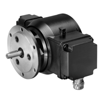
- Page 1 Montage- und Betriebsanleitung Mounting and operating instructions POG 10 + DSL Kombination Inkrementaler Drehgeber mit integriertem programmierbaren, digitalen Drehzahlschalter - EURO-Flansch B10 Combination Incremental encoder with integrated programmable, digital speed switch - EURO flange B10...
-
Page 2: Table Of Contents
Schritt 1 ..................................Schritt 2 ..................................Schritt 3 ..................................Schritt 4 ..................................Maximal zulässige Montagefehler unter Verwendung der Baumer Hübner Federscheibenkupplung K 35 ..................Hinweis bei Verwendung einer Klauenkupplung (zum Beispiel „ROTEX®“) ......Montagehinweis ..............................Abmessung ..................................... Elektrischer Anschluss .............................. - Page 3 Step 2 ..................................... Step 3 ................................... Step 4 ................................... Maximum permissible mounting tolerance when the Baumer Hübner K 35 spring disk coupling is used ................Note when using a jaw-type coupling (for example “ROTEX®”) ........... Mounting instruction ............................. Dimension ....................................
-
Page 4: Allgemeine Hinweise
Gebrauchte Elektro- und Elektronikgeräte dürfen nicht im Hausmüll entsorgt werden. Das Produkt enthält wertvolle Rohstoffe, die recycelt werden können. Wenn immer möglich sollen Altgeräte lokal am entsprechenden Sammeldepot entsorgt werden. Im Bedarfsfall gibt Baumer den Kunden die Möglichkeit, Baumer-Produkte fachgerecht zu entsor- gen. Weitere Informationen siehe www.baumer.com. Achtung! Beschädigung des auf dem Gerät befindlichen Siegels... -
Page 5: General Notes
Whenever possible, waste electrical and electronic equipment should be disposed locally at the authorized collection point. If necessary, Baumer gives customers the opportunity to dispose of Baumer products profession- ally. For further information see www.baumer.com. -
Page 6: Betrieb In Explosionsgefährdeten Bereichen
Betrieb in explosionsgefährdeten Bereichen Betrieb in explosionsgefährdeten Bereichen (nur bei Option ATEX) Das Gerät entspricht der Richtlinie 2014/34/EU für explosionsgefährdete Bereiche. Der Einsatz ist gemäß den Gerätekategorien 3 G (Ex-Atmosphäre Gas) und 3 D (Ex-Atmo- sphäre Staub) zulässig. Das Relaismodul DS 93 R, als Zubehör erhältlich, siehe Abschnitt 7.2.5, darf nicht in explosions- gefährdeten Bereichen eingesetzt werden. -
Page 7: Operation In Potentially Explosive Environments
Operation in potentially explosive environments Operation in potentially explosive environments (only with option ATEX) The device complies with the directive 2014/34/EU for potentionally explosive atmospheres. It can be used in accordance with equipment categories 3 G (explosive gas atmosphere) and 3 D (explosive dust atmosphere). -
Page 8: Sicherheitshinweise
Sicherheitshinweise Sicherheitshinweise Verletzungsgefahr durch rotierende Wellen Haare und Kleidungsstücke können von rotierenden Wellen erfasst werden. • Vor allen Arbeiten alle Betriebsspannungen ausschalten und Maschinen stillsetzen. Zerstörungsgefahr durch elektrostatische Aufladung Die elektronischen Bauteile im Gerät sind empfindlich gegen hohe Spannungen. • Steckkontakte und elektronische Komponenten nicht berühren. •... -
Page 9: Security Indications
Security indications Security indications Risk of injury due to rotating shafts Hair and clothes may become tangled in rotating shafts. • Before all work switch off all voltage supplies and ensure machinery is stationary. Risk of destruction due to electrostatic charge Electronic parts contained in the device are sensitive to high voltages. -
Page 10: Vorbereitung
Vorbereitung / Preparation Vorbereitung Preparation Lieferumfang Scope of delivery Gehäuse Housing EURO-Flansch B10 EURO flange B10 Vollwelle mit Passfeder Solid shaft with key Erdungsanschluss Earth connection Klemmenkastendeckel DSL Terminal box cover DSL Torxschraube M4x25 mm Torx screw M4x25 mm Federring 4, DIN 7980 Spring washer 4, DIN 7980 Kabelverschraubung M20x1,5 mm Cable gland M20x1.5 mm für Kabel ø5...13 mm... -
Page 11: Zur Montage Erforderlich (Nicht Im Lieferumfang Enthalten)
Vorbereitung / Preparation Zur Montage erforderlich Required for mounting (nicht im Lieferumfang enthalten) (not included in scope of delivery) Anbauvorrichtung, kundenspezifisch Installation fitting, customized Befestigungsschrauben M6x16 mm für An- Fixing screws M6x16 mm for installation fit- bauvorrichtung, ISO 4017 ting, ISO 4017 Federscheibenkupplung K 35, Spring disk coupling K 35, als Zubehör erhältlich, siehe Abschnitt 5.5. -
Page 12: Montage
Montage / Mounting Montage Mounting Schritt 1 Step 1 Anzugsmoment: Tightening torque: = 1 Nm 2.5 mm Schritt 2 Step 2 10 mm * Siehe Seite 7 oder 8 See page 7 or 8 Antriebswelle einfetten. Lubricate drive shaft. Die Antriebswelle sollte einen The drive shaft should have as less möglichst kleinen Rundlauffehler runout as possible because this can... -
Page 13: Schritt 3
Montage / Mounting Schritt 3 Step 3 10 mm Schritt 4 Step 4 Anzugsmoment: Tightening torque: = 1.3 ±10 % Nm 2.5 mm * Siehe Seite 8 See page 8 MB142 - 11055755 Baumer_POG10-DSL_II_DE-EN (20A2) -
Page 14: Maximal Zulässige Montagefehler Unter Verwendung Der Baumer Hübner Federscheibenkupplung K 35
Montage / Mounting Maximal zulässige Montagefehler Maximum permissible mounting toler- unter Verwendung der Baumer Hübner ance when the Baumer Hübner K 35 Federscheibenkupplung K 35 spring disk coupling is used Geräte mit Vollwelle sollten unter Verwen- Devices with a solid shaft should be dung der Baumer Hübner Federschei-... -
Page 15: Hinweis Bei Verwendung Einer Klauenkupplung (Zum Beispiel „Rotex®")
Montage / Mounting Hinweis bei Verwendung einer Klauen- Note when using a jaw-type coupling kupplung (zum Beispiel „ROTEX®“) (for example “ROTEX®”) Eine falsche Montage der Klauenkupplung Incorrect mounting of the jaw-type cou- führt zur Beschädigung des Gerätes. pling can damage the device. Mit einem Tiefenmessschieber die Use a depth gauge to find and observe korrekten Abstände (L, L1), siehe unten,... -
Page 16: Montagehinweis
Montage - Abmessung / Mounting - Dimension Montagehinweis Mounting instruction Wir empfehlen, das Gerät so zu It is recommended to mount the device montieren, dass der Kabelanschluss with cable connection facing down- keinem direkten Wassereintritt ward and being not exposed to water. ausgesetzt ist. Abmessung Dimension (75640, 75650) -
Page 17: Elektrischer Anschluss
Elektrischer Anschluss / Electrical connection Elektrischer Anschluss Electrical connection POG 10 POG 10 7.1.1 Beschreibung der Anschlüsse 7.1.1 Terminal significance Betriebsspannung Voltage supply Masseanschluss 0V ( ) Ground Erdungsanschluss (Gehäuse) Earth ground (housing) Ausgangssignal Kanal 1 Output signal channel 1 Ausgangssignal Kanal 1 invertiert Output signal channel 1 inverted Ausgangssignal Kanal 2 (90°... -
Page 18: Kabelanschluss
Elektrischer Anschluss / Electrical connection POG 10 POG 10 7.1.3 Kabelanschluss 7.1.3 Cable connection 7.1.3.1 Schritt 1 7.1.3.1 Step 1 TX 20 12 * 22 mm 7.1.3.2 Schritt 2 7.1.3.2 Step 2 TX 10 * Siehe Seite 7 oder 8 See page 7 or 8 MB142 - 11055755 Baumer_POG10-DSL_II_DE-EN (20A2) - Page 19 Elektrischer Anschluss / Electrical connection 7.1.3.3 Schritt 3 und 4 7.1.3.3 Step 3 and 4 13 * Ansicht X siehe Abschnitt 7.1.4. Kabelschirm View X Cable shield see section 7.1.4. ø5...13 mm Zur Gewährleistung der angegebenen To ensure the specified protection of Schutzart sind nur geeignete Kabel- the device the correct cable diameter durchmesser zu verwenden.
-
Page 20: Klemmenbelegung
Elektrischer Anschluss / Electrical connection POG 10 POG 10 7.1.3 Kabelanschluss 7.1.3 Cable connection 7.1.3.5 Schritt 6 7.1.3.5 Step 6 Anzugsmoment: Tightening torque: = 2...3 Nm TX 20 Großer, um 180° wendbarer Klemmenkasten. Big terminal box, turn by 180°. * Siehe Seite 7 oder 8 See page 7 or 8 Vor der Montage des Klemmenkasten- Check that the seal of the terminal box... -
Page 21: Dsl.r Für Den Betrieb Mit Einem Externem Relaismodul Ds 93 R (Zubehör)
Elektrischer Anschluss / Electrical connection DSL.R für den Betrieb mit einem exter- DSL.R suitable for operation with the nem Relaismodul DS 93 R (Zubehör) external relay modul DS 93 R (acces- sory) 7.2.1 Kabelanschluss 7.2.1 Cable connection Ansicht Y siehe Abschnitt 7.2.2. View Y see section 7.2.2. -
Page 22: Klemmenbelegung
RS485 Schnittstelle für PC oder Laptop (Adapter erforderlich). Interface for PC or Laptop (adapter required). Programmierung des DSL über Software zum Download unter www.baumer.com: Software für Windows XP Benutzerhandbuch für Windows XP Software für Windows 7-10 Benutzerhandbuch für Windows 7-10 Programming of the DSL via software available for download at www.baumer.com:... -
Page 23: Blockschaltbild
Elektrischer Anschluss / Electrical connection 7.2.3 Blockschaltbild 7.2.3 Block diagramm Kombination/Combination 15...30 VDC High = 12 V, Low = 0 V POG 10 DSL.R 0 V (GND) RS485 für/for PC/Laptop A, B 0 V (GND) 7.2.4 Ausgangsschaltverhalten 7.2.4 Switching characteristics 12 VDC 1,2,3 0 V (GND) -ns off -ns on... -
Page 24: Ds 93 R Relaismodul (Zubehör)
Elektrischer Anschluss / Electrical connection 7.2.5 DS 93 R Relaismodul (Zubehör) 7.2.5 DS 93 R relay modul (accessory) 7.2.5.1 Klemmenbelegung 7.2.5.1 Terminal assignment 3 Kontroll-LED‘s Höhe = 55 mm 3 control LEDs Kunststoffgehäuse für Tragschienenmontage (EN 50022) IP 20 Height = 55 mm 3 Relais/relays Plastic housing for ≤6 A / 250 VAC... -
Page 25: Dsl.e Mit Drei Internen Elektronischen Relais
Elektrischer Anschluss / Electrical connection DSL.E mit drei internen elektronischen DSL.E with three internal electronic Relais relays 7.3.1 Kabelanschluss 7.3.1 Cable connection Ansicht Z siehe Abschnitt 7.3.2. View Z see section 7.3.2. TX 20 Anzugsmoment: Tightening torque: = 2...3 Nm 22 mm Großer, um 180° wendbarer Klemmenkasten. Big terminal box, turn by 180°. -
Page 26: Klemmenbelegung
Abschnitt 7.3.1. Benutzerhandbuch für Windows 7-10 View Z Programming of the DSL via software available see section 7.3.1. for download at www.baumer.com: Software for Windows XP User manual for Windows XP Software for Windows 7-10 User manual for Windows 7-10... -
Page 27: Blockschaltbild
Sensor cable HEK 8 (Zubehör für POG 10) (accessory for POG 10) Es wird empfohlen, das Baumer Hübner Baumer Hübner sensor cable HEK 8 is Sensorkabel HEK 8 zu verwenden oder recommended. As a substitute a shielded ersatzweise ein geschirmtes, paarig ver- twisted pair cable should be used. -
Page 28: Demontage
Demontage / Dismounting Demontage Dismounting Schritt 1 Step 1 Elektrische Verbindung trennen. Disconnect electrical connection. TX 10 TX 20 22 mm 12 * * Siehe Seite 7 oder 8 See page 7 or 8 MB142 - 11055755 Baumer_POG10-DSL_II_DE-EN (20A2) - Page 29 Demontage / Dismounting Schritt 2 Step 2 Elektrische Verbindung trennen. Disconnect electrical connection. * Siehe Seite 7 See page 7 MB142 - 11055755 Baumer_POG10-DSL_II_DE-EN (20A2)
- Page 30 Demontage / Dismounting Schritt 3 Step 3 10 mm 2.5 mm Schritt 4 Step 4 Schritt 5 Step 5 2.5 mm * Siehe Seite 8 See page 8 MB142 - 11055755 Baumer_POG10-DSL_II_DE-EN (20A2)
-
Page 31: Eu-Konformitätserklärung
Signature/nom/fonction Baumer_POGxDSL_HOGxDSL_DE-EN-FR_CoC_81201223.docm/kwe Baumer Hübner GmbH P.O. Box 126943 ∙ D-10609 Berlin ∙ Max-Dohrn-Str. 2+4 ∙ D-10589 Berlin Phone +49 (0)30 69003-0 ∙ Fax +49 (0)30 69003-104 ∙ info@baumerhuebner.com ∙ www.baumer.com Sitz der Gesellschaft / Registered Office: Berlin, Germany ∙ Geschäftsführer / Managing Director: Dr. Oliver Vietze, Dr. Johann Pohany Handelsregister / Commercial Registry: AG Charlottenburg HRB 96409 ∙... -
Page 32: Technische Daten
Technische Daten Technische Daten 10.1 Technische Daten - elektrisch • Betriebsstrom ohne Last: ≤200 mA POG 10 + DSL.E • Betriebsspannung: 9...30 VDC POG 10 + DSL.R • Betriebsspannung: 15...30 VDC 10.2 Technische Daten - elektrisch (Drehgeber) • Impulse pro Umdrehung: 512...2500 (je nach Bestellung) •... -
Page 33: Technische Daten - Mechanisch
10.4 Technische Daten - mechanisch • Baugröße (Flansch): ø115 mm • Wellenart: ø11 mm Vollwelle • Zulässige Wellenbelastung: ≤300 N axial ≤450 N radial • Flansch: EURO-Flansch B10 • Schutzart DIN EN 60529: IP66 • Drehzahl (n): ≤6000 U/min (mechanisch) •... -
Page 34: Technical Data
Technical data Technical data 10.1 Technical data - electrical ratings • Consumption w/o load: ≤200 mA POG 10 + DSL.E • Voltage supply: 9...30 VDC POG 10 + DSL.R • Voltage supply: 15...30 VDC 10.2 Technical data - electrical ratings (encoder) • Pulses per revolution: 512...2500 (as ordered) •... -
Page 35: Technical Data - Mechanical Design
10.4 Technical data - mechanical design • Size (flange): ø115 mm • Shaft type: ø11 mm solid shaft • Admitted shaft load: ≤300 N axial ≤450 N radial • Protection DIN EN 60529: IP66 • Speed (n): ≤6000 rpm • Range of switching speed (ns ): Pulses = 512: ±16...6000 rpm Pulses = 1024: ±8...6000 rpm Pulses = 2048:... -
Page 36: Zubehör
• Analyzer for encoders HENQ 1100 HENQ 1100 * Siehe Abschnitt 4 See section 4 Baumer Hübner GmbH Originalsprache der Anleitung ist Deutsch. P.O. Box 12 69 43 · 10609 Berlin, Germany Technische Änderungen vorbehalten. Phone: +49 (0)30/69003-0 · Fax: +49 (0)30/69003-104 Original language of this instruction is German.