
Related Manuals for Baumer HUBNER BERLIN HOG 8


Summary of Contents for Baumer HUBNER BERLIN HOG 8
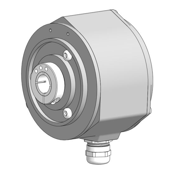
- Page 1 Montage- und Betriebsanleitung Mounting and operating instructions HOG 8 Inkrementaler Drehgeber Incremental encoder...
-
Page 2: Table Of Contents
Inhaltsverzeichnis Inhaltsverzeichnis Allgemeine Hinweise ..............................Sicherheitshinweise ..............................Vorbereitung .................................. Lieferumfang ..............................Zur Montage erforderlich (nicht im Lieferumfang enthalten) ........... Zusätzlich erforderlich bei Standardversion (nicht im Lieferumfang enthalten) .... Zusätzlich erforderlich für Montage mit Stützblech (nicht im Lieferumfang enthalten) ......................Erforderliches Werkzeug (nicht im Lieferumfang enthalten) ........... - Page 3 Table of contents Table of contents General notes ................................Security indications ..............................Preparation ..................................Scope of delivery ............................Required for mounting (not included in scope of delivery) ............Additionally required for standard version (not included in scope of delivery) ....Additionally required for mounting with support plate (not included in scope of delivery) ......................
-
Page 4: Allgemeine Hinweise
Gebrauchte Elektro- und Elektronikgeräte dürfen nicht im Hausmüll entsorgt werden. Das Produkt enthält wertvolle Rohstoffe, die recycelt werden können. Wenn immer möglich sollen Altgeräte lokal am entsprechenden Sammeldepot entsorgt werden. Im Bedarfsfall gibt Baumer den Kunden die Möglichkeit, Baumer-Produkte fachgerecht zu entsor- gen. Weitere Informationen siehe www.baumer.com. Achtung! Beschädigung des auf dem Gerät befindlichen Siegels... -
Page 5: General Notes
Whenever possible, waste electrical and electronic equipment should be disposed locally at the authorized collection point. If necessary, Baumer gives customers the opportunity to dispose of Baumer products profession- ally. For further information see www.baumer.com. -
Page 6: Sicherheitshinweise
Sicherheitshinweise Sicherheitshinweise Verletzungsgefahr durch rotierende Wellen Haare und Kleidungsstücke können von rotierenden Wellen erfasst werden. • Vor allen Arbeiten alle Betriebsspannungen ausschalten und Maschinen stillsetzen. 2.2 Zerstörungsgefahr durch elektrostatische Aufladung Die elektronischen Bauteile im Gerät sind empfindlich gegen hohe Spannungen. • Steckkontakte und elektronische Komponenten nicht berühren. •... -
Page 7: Security Indications
Security indications Security indications Risk of injury due to rotating shafts Hair and clothes may become tangled in rotating shafts. • Before all work switch off all voltage supplies and ensure machinery is stationary. Risk of destruction due to electrostatic charge Electronic parts contained in the device are sensitive to high voltages. -
Page 8: Vorbereitung
Vorbereitung / Preparation Vorbereitung Preparation Lieferumfang Scope of delivery Gehäuse Housing Durchgehende Hohlwelle Through hollow shaft Klemmring Clamping ring Torxschraube M3x12 mm Torx screw M3x12 mm Gewindestift ISO 4029, M4x6 mm Setscrew ISO 4029, M4x6 mm Abdeckhaube Cover Torxschraube M3x12 mm Torx screw M3x12 mm Kabelverschraubung M16x1,5 mm Cable gland M16x1.5 mm für Kabel ø5...9 mm... -
Page 9: Zur Montage Erforderlich (Nicht Im Lieferumfang Enthalten)
Vorbereitung / Preparation Zur Montage erforderlich Required for mounting (nicht im Lieferumfang enthalten) (not included in scope of delivery) HEK 8 Sensorkabel, HEK 8 sensor cable, als Zubehör erhältlich, siehe Abschnitt 6.5. available as accessory, see section 6.5. Zusätzlich erforderlich bei Standard- Additionally required for standard ver- version sion... -
Page 10: Zusätzlich Erforderlich Für Montage Mit Stützblech (Nicht Im Lieferumfang Enthalten)
Vorbereitung / Preparation Zusätzlich erforderlich für Montage mit Additionally required for mounting Stützblech with support plate (nicht im Lieferumfang enthalten) (not included in scope of delivery) Drehmomentstütze, als Zubehör erhältlich: Torque arm, available as accessory: Bestellnummer Länge L, Version Order number Length L, version 11043628 67...70 mm, Standard 11043628... -
Page 11: Montage
Montage / Mounting Montage Mounting Mit Drehmomentblech (Standard) With torque sheet (standard) 4.1.1 Schritt 1 4.1.1 Step 1 TX 10 4.1.2 Schritt 2 4.1.2 Step 2 TX 10 (Hohlwelle / Hollow shaft ø10, 12 mm) 2 mm (Hohlwelle / Hollow shaft ø14, 15, 16 mm) * Siehe Seite 5 oder 6 See page 5 or 6 MB148 - 11055761... -
Page 12: Schritt 3
Montage / Mounting 4.1.3 Schritt 3 4.1.3 Step 3 2.5 mm Anzugsmoment: Tightening torque: = 2...2.5 Nm Antriebswelle einfetten. Lubricate drive shaft. Die Antriebswelle sollte einen The drive shaft should have as less möglichst kleinen Rundlauffehler runout as possible because this can aufweisen, da dieser zu einem otherwise result in an angle error, see Winkelfehler führen kann, siehe... -
Page 13: Mit Stützblech Und Drehmomentstütze
Montage / Mounting Mit Stützblech und Drehmomentstütze With support plate and torque arm 4.2.1 Schritt 1 4.2.1 Step 1 10 mm 10 mm 4.2.2 Schritt 2 4.2.2 Step 2 TX 10 (Hohlwelle / Hollow shaft ø10, 12 mm) 2 mm (Hohlwelle / Hollow shaft ø14, 15, 16 mm) * Siehe Seite 5 oder 7 See page 5 or 7 MB148 - 11055761... -
Page 14: Schritt 3
Montage / Mounting 4.2.3 Schritt 3 4.2.3 Step 3 10 mm * Siehe Seite 7 See page 7 Antriebswelle einfetten. Lubricate drive shaft. Die Antriebswelle sollte einen The drive shaft should have as less möglichst kleinen Rundlauffehler runout as possible because this can aufweisen, da dieser zu einem otherwise result in an angle error, see Winkelfehler führen kann, siehe... -
Page 15: Schritt 4 - Drehmomentstütze
Montage / Mounting 4.2.4 Schritt 4 - Drehmomentstütze 4.2.4 Step 4 - Torque arm Die Montage der Drehmomentstütze The torque arm should be mounted sollte spielfrei erfolgen. Ein Spiel von free from clearance. A play of just beispielsweise ±0,03 mm entspricht ±0.03 mm, results in a runout of the einem Rundlauffehler des Gerätes von device of 0.06 mm. -
Page 16: Hinweis Zur Vermeidung Von Messfehlern
Montage / Mounting 4.2.5 Hinweis zur Vermeidung von Messfeh- 4.2.5 How to prevent measurement errors lern Für einen einwandfreien Betrieb des To ensure that the device operates cor- Gerätes ist eine korrekte Montage, ins- rectly, it is necessary to mount it ac- besondere auch der Drehmomentstütze, curately as described in section 4.2.1 to notwendig, wie beschrieben in Abschnitt... -
Page 17: Schritt 5
Montage / Mounting 4.2.6 Schritt 5 4.2.6 Step 5 TX 10 (Hohlwelle / Hollow shaft ø10, 12 mm) 2 mm (Hohlwelle / Hollow shaft ø14, 15, 16 mm) * Siehe Seite 5 See page 5 MB148 - 11055761 Baumer_HOG8_II_DE-EN (20A1) -
Page 18: Abmessungen
Abmessungen / Dimensions Abmessungen Dimensions Mit Drehmomentblech (Standard) With torque sheet (standard) (73300, 73314) (73300, 73314) Zubehör Accessory ød Positive Drehrichtung Positive rotating direction Mit Stützblech für Drehmomentstütze With support plate for torque arm (73306) (73306) Positive Drehrichtung Positive rotating direction ød Zubehör Accessory Alle Abmessungen in Millimeter (wenn nicht anders angegeben) -
Page 19: Elektrischer Anschluss
Elektrischer Anschluss / Electrical connection Elektrischer Anschluss Electrical connection Kabelanschluss Cable connection 6.1.1 Schritt 1 6.1.1 Step 1 TX 10 17 mm 6.1.2 Schritt 2 6.1.2 Step 2 Kabelschirm Cable shield Ansicht X siehe Abschnitt 6.4. View X see section 6.4. ø5...9 mm * Siehe Seite 5 oder 6 See page 5 or 6 Zur Gewährleistung der angegebenen... -
Page 20: Beschreibung Der Anschlüsse
Elektrischer Anschluss / Electrical connection Beschreibung der Anschlüsse 6.2 Terminal significance Betriebsspannung Voltage supply Masseanschluss 0V ( ) Ground Erdungsanschluss (Gehäuse) Earth ground (housing) Ausgangssignal Kanal 1 Output signal channel 1 Ausgangssignal Kanal 1 invertiert Output signal channel 1 inverted Ausgangssignal Kanal 2 (90° versetzt zu Kanal 1) Output signal channel 2 (offset by 90°... -
Page 21: Anschlussbelegung
Elektrischer Anschluss / Electrical connection Anschlussbelegung Connecting assignment 6.4.1 D … C 6.4.1 D … C Ansicht X Anschlussklemmen, siehe Abschnitt 6.1.2. View X connecting terminal, see section 6.1.2. 0V ( ) Betriebsspannung nicht auf Ausgänge Do not connect voltage supply to outputs! Danger of damage! legen! Zerstörungsgefahr! Spannungsabfälle in langen Leitungen Please, beware of possible voltage drop... -
Page 22: Sensorkabel Hek 8 (Zubehör)
(inputs and outputs). Sensorkabel HEK 8 (Zubehör) Sensor cable HEK 8 (accessory) Es wird empfohlen, das Baumer Hübner Baumer Hübner sensor cable HEK 8 is Sensorkabel HEK 8 zu verwenden oder recommended. As a substitute a shielded ersatzweise ein geschirmtes, paarig ver- twisted pair cable should be used. -
Page 23: Demontage
Demontage / Dismounting Demontage Dismounting Elektrische Verbindung trennen Disconnect electrical connection 7.1.1 Schritt 1 7.1.1 Step 1 TX 10 17 mm 7.1.2 Schritt 2 7.1.2 Step 2 * Siehe Seite 5 oder 6 See page 5 or 6 MB148 - 11055761 Baumer_HOG8_II_DE-EN (20A1) -
Page 24: Mit Drehmomentblech (Standard)
Demontage / Dismounting Mit Drehmomentblech (Standard) With torque sheet (standard) 7.2.1 Schritt 1 7.2.1 Step 1 TX 10 (Hohlwelle / Hollow shaft ø10, 12 mm) 2 mm (Hohlwelle / Hollow shaft ø14, 15, 16 mm) 7.2.2 Schritt 2 7.2.2 Step 2 2.5 mm * Siehe Seite 5 oder 6 See page 5 or 6 MB148 - 11055761 Baumer_HOG8_II_DE-EN (20A1) -
Page 25: Mit Stützblech Und Drehmomentstütze
Demontage / Dismounting 7.2.3 Schritt 3 7.2.3 Step 3 Mit Stützblech und Drehmomentstütze With support plate and torque arm 7.3.1 Schritt 1 7.3.1 Step 1 TX 10 (Hohlwelle / Hollow shaft ø10, 12 mm) 2 mm (Hohlwelle / Hollow shaft ø14, 15, 16 mm) * Siehe Seite 5 See page 5 MB148 - 11055761 Baumer_HOG8_II_DE-EN (20A1) - Page 26 Demontage / Dismounting 7.3.2 Schritt 2 7.3.2 Step 2 10 mm 7.3.3 Schritt 3 7.3.3 Step 3 * Siehe Seite 7 See page 7 MB148 - 11055761 Baumer_HOG8_II_DE-EN (20A1)
-
Page 27: Zubehör
Zubehör / Accessories Zubehör Accessories • Drehmomentblech Montageset: • Torque sheet mounting kit: Bestellnummer 11077218 Order number 11077218 • Drehmomentstütze Größe M6: • Torque arm size M6: Bestellnummer siehe Order number see Abschnitt 3.4 section 3.4 • Montageset für Drehmoment- • Mounting kit for torque arm: stütze: Bestellnummer 11071904 Order number 11071904 •... -
Page 28: Technische Daten
Montage / Mounting Technische Daten Technische Daten Technische Daten - elektrisch • Betriebsspannung: 9...26 VDC (HTL, TTL - Version R) 5 VDC ±5 % (TTL) • Betriebsstrom ohne Last: ≤100 mA • Impulse pro Umdrehung: 1...5000 (je nach Bestellung) • Phasenverschiebung: 90°... -
Page 29: Technical Data
Technical data Technical data Technical data - electrical ratings • Voltage supply: 9...26 VDC (HTL, TTL - version R) 5 VDC ±5 % (TTL) • Consumption w/o load: ≤100 mA • Pulses per revolution: 1...5000 (as ordered) • Phase shift: 90° ±20° • Duty cycle: 40...60 % •... - Page 30 MB148 - 11055761 Baumer_HOG8_II_DE-EN (20A1)
- Page 31 MB148 - 11055761 Baumer_HOG8_II_DE-EN (20A1)
- Page 32 Baumer Hübner GmbH P.O. Box 12 69 43 · 10609 Berlin, Germany Phone: +49 (0)30/69003-0 · Fax: +49 (0)30/69003-104 info@baumerhuebner.com · www.baumer.com/motion Version: 73300, 73306, 73314 MB148 - 11055761 Baumer_HOG8_II_DE-EN (20A1-19.02.2020)