Baumer HUBNER BERLIN HOG 28 Mounting And Operating Instructions
Incremental encoder with clamping set
Hide thumbs
Also See for HUBNER BERLIN HOG 28:
- Mounting and operating instructions (40 pages) ,
- Installation and operating instructions manual (36 pages)

Related Manuals for Baumer HUBNER BERLIN HOG 28


Summary of Contents for Baumer HUBNER BERLIN HOG 28
- Page 1 Montage- und Betriebsanleitung Mounting and operating instructions HOG 28 Inkrementaler Drehgeber mit Spannsatz Incremental encoder with clamping set...
-
Page 2: Table Of Contents
Inhaltsverzeichnis Inhaltsverzeichnis Allgemeine Hinweise ................................Betrieb in explosionsgefährdeten Bereichen ....................Sicherheitshinweise ................................Vorbereitung .................................... Lieferumfang ................................Zur Montage erforderlich (nicht im Lieferumfang enthalten) ............. Erforderliches Werkzeug (nicht im Lieferumfang enthalten) ............. Montage ....................................... Schritt 1 ..................................Schritt 2 ..................................Schritt 3 .................................. - Page 3 Table of contents Table of contents General notes ..................................Operation in potentially explosive environments ................... Security indications ................................Preparation ....................................Scope of delivery ..............................Required for mounting (not included in scope of delivery) ..............Required tools (not included in scope of delivery) ..................
-
Page 4: Allgemeine Hinweise
Gebrauchte Elektro- und Elektronikgeräte dürfen nicht im Hausmüll entsorgt werden. Das Produkt enthält wertvolle Rohstoffe, die recycelt werden können. Wenn immer möglich sollen Altgeräte lokal am entsprechenden Sammeldepot entsorgt werden. Im Bedarfsfall gibt Baumer den Kunden die Möglichkeit, Baumer-Produkte fachgerecht zu entsor- gen. Weitere Informationen siehe www.baumer.com. Achtung! Beschädigung des auf dem Gerät befindlichen Siegels... -
Page 5: General Notes
Whenever possible, waste electrical and electronic equipment should be disposed locally at the authorized collection point. If necessary, Baumer gives customers the opportunity to dispose of Baumer products profession- ally. For further information see www.baumer.com. -
Page 6: Betrieb In Explosionsgefährdeten Bereichen
Betrieb in explosionsgefährdeten Bereichen Betrieb in explosionsgefährdeten Bereichen (nur bei Option ATEX) Das Gerät entspricht der Richtlinie 2014/34/EU für explosionsgefährdete Bereiche. Der Einsatz ist gemäß den Gerätekategorien 3 G (Ex-Atmosphäre Gas) und 3 D (Ex-Atmo- sphäre Staub) zulässig. Gerätekategorie 3 G: - Ex-Kennzeichnung: II 3 G Ex ec IIC T4 Gc - Normenkonformität:... -
Page 7: Operation In Potentially Explosive Environments
Operation in potentially explosive environments Operation in potentially explosive environments (only with option ATEX) The device complies with the directive 2014/34/EU for potentionally explosive atmospheres. It can be used in accordance with equipment categories 3 G (explosive gas atmosphere) and 3 D (explosive dust atmosphere). -
Page 8: Sicherheitshinweise
Sicherheitshinweise Sicherheitshinweise Verletzungsgefahr durch rotierende Wellen Haare und Kleidungsstücke können von rotierenden Wellen erfasst werden. • Vor allen Arbeiten alle Betriebsspannungen ausschalten und Maschinen stillsetzen. Zerstörungsgefahr durch elektrostatische Aufladung Die elektronischen Bauteile im Gerät sind empfindlich gegen hohe Spannungen. • Steckkontakte und elektronische Komponenten nicht berühren. •... -
Page 9: Security Indications
Security indications Security indications Risk of injury due to rotating shafts Hair and clothes may become tangled in rotating shafts. • Before all work switch off all voltage supplies and ensure machinery is stationary. Risk of destruction due to electrostatic charge Electronic parts contained in the device are sensitive to high voltages. •... -
Page 10: Vorbereitung
Vorbereitung / Preparation Vorbereitung Preparation Lieferumfang Scope of delivery Gehäuse Housing Durchgehende Through Hohlwelle hollow shaft Spannelement Clamping element Druckring Pressure ring 8x Befestigungsschraube M4x12 mm, ISO 4762 8x fixing screw M4x12 mm, ISO 4762 Stütze für Drehmomentstütze Brace for torque arm Sechskantschraube ø12 mm auf M10x35 mm Hexagon screw ø12 mm to M10x35 mm Scheibe A13, ISO 7090 Washer A13, ISO 7090... -
Page 11: Zur Montage Erforderlich (Nicht Im Lieferumfang Enthalten)
Vorbereitung / Preparation Zur Montage erforderlich Required for mounting (nicht im Lieferumfang enthalten) (not included in scope of delivery) 16b 16c 3x 3x Drehmomentstütze, als Zubehör erhältlich: Torque arm, available as accessory: Bestellnummer Länge L, Version Order number Length L, version 11054922 155 (-10/+15) mm, Standard 11054922 155 (-10/+15) mm, standard... -
Page 12: Montage
Montage / Mounting Montage Mounting Schritt 1 Step 1 17 mm 19 mm Schritt 2 Step 2 Schrauben leicht lösen. Untighten the screws a little bit. 3 mm * Siehe Seite 7 oder 8 See page 7 or 8 MB178aT1 - 11067736 Baumer_HOG28A_T1_DE_EN_202201_MI_11067736 (22A1) -
Page 13: Schritt 3
Montage / Mounting Schritt 3 Step 3 18 mm 11 * * Siehe Seite 7 oder 8 1.6x8 mm See page 7 or 8 Antriebswelle einfetten. Lubricate drive shaft. Das Gerät nicht über das Gerätege- Apply mounting force only via device häuse sondern nur über die Geräte- shaft, never via device housing to welle auf die Antriebswelle schieben. -
Page 14: Schritt 4 - Drehmomentstütze
Montage / Mounting Schritt 4 - Drehmomentstütze Step 4 - Torque arm Die Montage der Drehmomentstütze The torque arm should be mounted sollte spielfrei erfolgen. Ein Spiel von free from clearance. A play of just beispielsweise ±0,03 mm entspricht ±0.03 mm, results in a runout of the einem Rundlauffehler des Gerätes von device of 0.06 mm. -
Page 15: Hinweis Zur Vermeidung Von Messfehlern
Montage / Mounting Hinweis zur Vermeidung von How to prevent measurement errors Messfehlern Für einen einwandfreien Betrieb des To ensure that the device operates cor- Gerätes ist eine korrekte Montage, ins- rectly, it is necessary to mount it accu- besondere auch der Drehmomentstütze, rately as described in section 5.1 to 5.4, notwendig, wie beschrieben in Abschnitt which includes correct mounting of the... -
Page 16: Schritt 5
Montage / Mounting Schritt 5 Step 5 3 mm Anzugsmoment: Tightening torque: = 3...4 Nm * Siehe Seite 7 See page 7 MB178aT1 - 11067736 Baumer_HOG28A_T1_DE_EN_202201_MI_11067736 (22A1) -
Page 17: Abmessungen
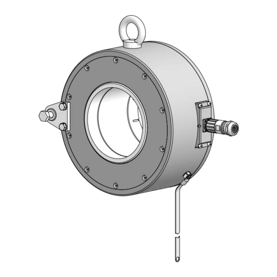
Abmessungen / Dimensions Abmessungen Dimensions Mit Klemmenkasten With terminal box (74285) (74285) Drehrichtung positiv Transportöse Positive rotating direction Eye bolt ø419 Zubehör Accessory Mit Flanschdose M23 und Rundsteck- With flange connector M23 and mating verbinder connector (74280) (74280) Transportöse Drehrichtung positiv Eye bolt Positive rotating direction ø419 Zubehör... -
Page 18: Elektrischer Anschluss
Elektrischer Anschluss / Electrical connection Elektrischer Anschluss Electrical connection Beschreibung der Anschlüsse Terminal significance Betriebsspannung Voltage supply Masseanschluss 0V ( ) Ground Erdungsanschluss (Gehäuse) Earth ground (housing) Ausgangssignal Kanal 1 Output signal channel 1 Ausgangssignal Kanal 1 invertiert Output signal channel 1 inverted Ausgangssignal Kanal 2 (90°... -
Page 19: Mit Klemmenkasten
Elektrischer Anschluss / Electrical connection Mit Klemmenkasten With terminal box 7.3.1 Kabelanschluss Schritt 1 7.3.1 Cable connection step 1 12b * TX 20 22 mm 7.3.2 Kabelanschluss Schritt 2 7.3.2 Cable connection step 2 TX 10 * Siehe Seite 7 See page 7 MB178aT1 - 11067736 Baumer_HOG28A_T1_DE_EN_202201_MI_11067736 (22A1) -
Page 20: Kabelanschluss Schritt 3
Elektrischer Anschluss / Electrical connection Mit Klemmenkasten With terminal box 7.3.3 Kabelanschluss Schritt 3 7.3.3 Cable connection step 3 Ansicht X siehe Abschnitt 7.3.6 und 7.3.7. Kabelschirm View X Cable shield see section 7.3.6 and 7.3.7. 12c * ø5...13 mm Zur Gewährleistung der angegebenen To ensure the specified protection of Schutzart sind nur geeignete Kabel- the device the correct cable diameter... -
Page 21: Kabelanschluss Schritt 5
Elektrischer Anschluss / Electrical connection 7.3.5 Kabelanschluss Schritt 5 7.3.5 Cable connection step 5 12b * TX 20 Großer, um 180° Anzugsmoment: wendbarer Klemmenkasten. Tightening torque: Big terminal box, = 2...3 Nm turn by 180°. * Siehe Seite 7 oder 8 See page 7 or 8 Vor der Montage des Klemmenkasten- Check that the seal of the terminal box deckels prüfen, ob die Klemmenka-... -
Page 22: Anschlussklemmen Dn
Elektrischer Anschluss / Electrical connection Mit Klemmenkasten With terminal box 7.3.6 Anschlussklemmen 7.3.6 Connecting terminal DN … C DN … C Max. 1,5 mm Ansicht X Anschlussklemmen, Max. AWG 16 siehe Abschnitt 7.1.3. View X Connecting terminal, see section 7.1.3. Zwischen besteht keine Verbindung. There is no connection between 7.3.7 Anschlussklemmen 7.3.7... -
Page 23: Mit Flanschdose Und Rundsteckverbinder
Elektrischer Anschluss / Electrical connection Mit Flanschdose und Rundsteckverbin- With flange connector and mating con- nector 7.4.1 Kabelanschluss Schritt 1 7.4.1 Cable connection step 1 Ansicht Y Löteinsatz, Belegung siehe ø7...12 mm Abschnitt 7.4.3. View Y Kabelschirm Insert with solder contacts, Cable shield assignment see section 7.4.3. -
Page 24: Kabelanschluss Schritt 2
Elektrischer Anschluss / Electrical connection Mit Flanschdose und Rundsteckverbin- With flange connector and mating con- nector 7.4.2 Kabelanschluss Schritt 2 7.4.2 Cable connection step 2 Ansicht Z siehe Abschnitt 7.4.3. View Z see section 7.4.3. Handfest Hand-tight * Siehe Seite 7 See page 7 Wir empfehlen, das Gerät so zu It is recommended to mount the device montieren, dass der Kabelanschluss... -
Page 25: Pinbelegung Flanschdose
(inputs and outputs). Sensorkabel HEK 8 (Zubehör) Sensor cable HEK 8 (accessory) Es wird empfohlen, das Baumer Hübner Baumer Hübner sensor cable HEK 8 is Sensorkabel HEK 8 zu verwenden oder recommended. As a substitute a shielded ersatzweise ein geschirmtes, paarig ver- twisted pair cable should be used. -
Page 26: Austausch Der Einschubelektronik (Zubehör)
Austausch der Einschubelektronik (Zubehör) / Plug-in electronics replacement (accessories) Austausch der Einschub- Plug-in electronics replacement elektronik (Zubehör) (accessories) Mit Klemmenkasten With terminal box 8.1.1 Lieferumfang 8.1.1 Scope of delivery Einschubelektronik mit Klemmenkasten, Plug-in electronics with terminal box, als Zubehör erhältlich: available as accessory: Klemmenkastendeckel Terminal box cover Torx-/Schlitzschraube M4x32 mm Torx/slotted screw M4x32 mm Kabelverschraubung M20x1,5 mm... -
Page 27: Montage
Austausch der Einschubelektronik (Zubehör) / Plug-in electronics replacement (accessories) 8.1.2 Montage 8.1.2 Mounting 3 mm Führungsstift Guide pin 12g * Führungsnut Guide slot TX 20 * Siehe Seite 23 See page 23 Elektrischer Anschluss und Klemmen- Electrical connection and terminal belegung wie in Abschnitt 7.3 be- assignment as described in section schrieben. -
Page 28: Mit Flanschdose Und Rundsteckverbinder
Austausch der Einschubelektronik (Zubehör) / Plug-in electronics replacement (accessories) Mit Flanschdose und Rundsteckverbin- With flange connector and mating con- nector 8.2.1 Lieferumfang 8.2.1 Scope of delivery Einschubelektronik mit Flanschdose und Plug-in electronics with flange connector and Rundsteckverbinder, als Zubehör erhältlich: mating connector, available as accessory: Flanschdose M23, 12-polig, Flange connector M23, 12-pin, Stiftkontakte, rechtsdrehend, male, CW, siehe Abschnitt 7.4.2 und 7.4.3. -
Page 29: Montage
Austausch der Einschubelektronik (Zubehör) / Plug-in electronics replacement (accessories) 8.2.2 Montage 8.2.2 Mounting Führungsstift 3 mm Guide pin 13c * Führungsnut Guide slot Handfest Hand-tight * Siehe Seite 25 See page 25 Elektrischer Anschluss und Pinbele- Electrical connection and pin gung wie in Abschnitt 7.4 beschrieben. assignment such as described in section 7.4. -
Page 30: Demontage
Demontage / Dismounting Demontage Dismounting Schritt 1 Step 1 TX 20 TX 10 22 mm * Siehe Seite 7 oder 8 See page 7 or 8 MB178aT1 - 11067736 Baumer_HOG28A_T1_DE_EN_202201_MI_11067736 (22A1) - Page 31 Demontage / Dismounting Schritt 2 Step 2 3 mm 11 * 18 mm 1.6x8 mm Schritt 3 Step 3 * Siehe Seite 7 oder 8 See page 7 or 8 Das Gerät nicht über das Gerätege- Apply force only via the device shaft, häuse sondern nur über die Geräte- never via the device housing to welle von der Antriebswelle abziehen.
-
Page 32: Technische Daten
Technische Daten Technische Daten 10.1 Technische Daten - elektrisch • Betriebsspannung: 9...26 VDC (HTL - Version C, TTL - Version R) 5 VDC ±5 % (TTL) • Betriebsstrom ohne Last: ≤100 mA • Impulse pro Umdrehung: 1024...2048 (je nach Bestellung) •... -
Page 33: Technical Data
Technical data Technical data 10.1 Technical data - electrical ratings • Voltage supply: 9...26 VDC (HTL - version C, TTL - version R) 5 VDC ±5 % (TTL) • Consumption w/o load: ≤100 mA • Pulses per revolution: 1024...2048 (as ordered) • Phase shift: 90°... -
Page 34: Zubehör
Montage / Mounting Zubehör / Accessories Zubehör Accessories • Drehmomentstütze Größe M12: • Torque arm size M12: Bestellnummer siehe Order number see Abschnitt 4.2 section 4.2 • Montageset für Drehmomentstütze • Mounting kit for torque arm Größe M12 und Erdungsband: size M12 and earthing strap: Bestellnummer 11069336 Order number 11069336 • Sensorkabel für Drehgeber •... - Page 35 MB178aT1 - 11067736 Baumer_HOG28A_T1_DE_EN_202201_MI_11067736 (22A1)
- Page 36 Baumer Hübner GmbH P.O. Box 12 69 43 · 10609 Berlin, Germany Phone: +49 (0)30/69003-0 · Fax: +49 (0)30/69003-104 info@baumerhuebner.com · www.baumer.com/motion Version: 74280, 74285 MB178aT1 - 11067736 Baumer_HOG28A_T1_DE_EN_202201_MI_11067736 (22A1-20.01.2022)