Advertisement
Installa on Instruc ons and
Use & Care Guide
Heat Pump Water Heater
DO NOT RETURN THIS UNIT TO THE STORE
Read this manual and the labels on the water heater before you install,
operate, or service it. If you have diffi culty following the direc ons, or
aren't sure you can safely and properly do any of this work yourself:
• Call our Technical Assistance Hotline at 1-888-479-8324 . We can help you with
installation, operations, troubleshooting, or maintenance. Before you call, write
down the model and serial number from the water heater's data plate.
Incorrect installa on, opera on, or service can damage the water heater, your house
and other property, and present risks including fi re, scalding, electric shock, and
explosion, causing serious injury or death.
LOW LEAD
CONTENT
Table of Contents
IMPORTANT SAFETY INFORMATION ................................. 3
GETTING STARTED ............................................................ 6
INSTALLATION ................................................................... 7
DIAGNOSTIC CODES ........................................................ 20
TROUBLESHOOTING CHART ........................................... 22
MAINTENANCE ............................................................... 28
REPAIR PARTS ILLUSTRATION .......................................... 33
Keep this manual in the pocket on heater for future reference whenever maintenance, adjustment or service is required.
Hybrid Electric
Retain your original receipt as proof of purchase.
Page
November 2015
100269085
Advertisement

Related Manuals for A.O. Smith Vortex HPTU-50


Summary of Contents for A.O. Smith Vortex HPTU-50
-
Page 1: Table Of Contents
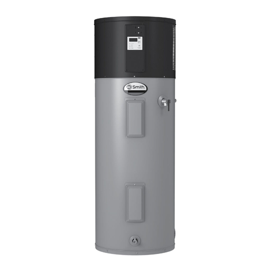
Installa on Instruc ons and Use & Care Guide Hybrid Electric Heat Pump Water Heater DO NOT RETURN THIS UNIT TO THE STORE Read this manual and the labels on the water heater before you install, operate, or service it. If you have diffi culty following the direc ons, or aren’t sure you can safely and properly do any of this work yourself: •... - Page 2 COMPLETED INSTALLATION TYPICAL Condensate Drain Air Filter Access Cover (See Figure 15, p.12) Connectivity Port User Interface Module (UIM) Temperature and Shut-off Valve Pressure Relief Valve (Hot) Upper Element and ECO (Outlet) Primary Condensate Drain (3/4” PVC) Discharge Pipe (Do Not Cap or Plug) Thermal Expansion Tank Lower Element Cold...
-
Page 3: Important Safety Information
IMPORTANT SAFETY INFORMATION Read and follow all safety messages and instruc ons in Important informa on to keep this manual. Fill out this sec on and keep this manual in the pocket of the water This is the safety alert symbol. It is used to alert you to heater for reference. - Page 4 IMPORTANT SAFETY INFORMATION o reduce the risk of property RISKS DURING OPERATION For informa on about changing the damage, serious injury or death, factory thermostat se ng(s), refer to Scalding Risk read and follow the precau ons below, the “Adjusting the This water heater all labels on the water heater, and Temperature”...
- Page 5 IMPORTANT SAFETY INFORMATION According to a na onal standard • Keep the water heater from becom- Maintain the T&P Relief Valve properly. American Society of Sanitary Engineer- ing wet. Immediately shut the water Follow the maintenance instructions ing (ASSE 1070) and most local plumbing heater off and have it inspected by a provided by the manufacturer of the codes, the water heater’s thermostat...
-
Page 6: Getting Started
GETTING STARTED Review all of the instruc ons • Teflon® tape or pipe joint com- pound approved for potable water before you begin work. Improper installa on can • Tools to make the electrical connec- damage the water heater, your home tions (for example, screwdrivers, and other property, and can present wire strippers) -
Page 7: Installation
INSTALLATION ✓ Follow these steps for proper Water pressure installa on: increase caused by Step 1: thermal expansion Verify that you have a properly sized ✓ Verify that your Thermal Expansion Tank (Figure 7). We home is equipped recommend installing an expansion tank if your home does not have one. - Page 8 INSTALLATION BACKGROUND: Water expands when . WARNING! Even if the water heater thermostat is set to a rela vely heated, and the increased volume low temperature, hot water can scald. of water must have a place to go, or Install Thermosta c Mixing Valves thermal expansion will cause large to reduce the risk of scalding (page increases in water pressure (despite...
- Page 9 INSTALLATION The loca on has adequate The site loca on must be The loca on is not prone to space (clearances) for period- free from any corrosive physical damage by vehicles, ic servicing. For op mal water elements in the atmosphere fl...
- Page 10 INSTALLATION Step 3: WARNING! Be sure the water runs When the tank is empty, cool before draining the tank to re- disconnect the Temperature & Removing the old water duce the risk of scalding. Pressure (T&P) Relief Valve discharge pipe. You may be able to heater Connect a garden hose to reuse the discharge pipe, but do not...
- Page 11 INSTALLATION Step 4: • There is adequate access and space Locate the white 22 AWG wire around the water heater for future loop inside the condensate maintenance. A minimum clearance Installing the new drain access compartment by of 6in (150mm) must be maintained removing the 4 screws attaching the water heater from all sides and 6in (150mm) from...
- Page 12 INSTALLATION • If a condensate pump is installed, WARNING! To avoid serious injury Condensate Drain Access Cover or death from explosion, install a T&P it should be wired to shut off the Primary Drain Relief Valve according to the following heat pump in the event the con- Connection instruc ons:...
- Page 13 INSTALLATION Terminate the discharge pipe Install a Thermosta c Mixing Step 9: a maximum of 12” (300mm) Valve . Consult the valve Connect the water above a fl oor drain, sump or manufacturer’s instruc ons or supply other safe loca on . Do not drain the a qualifi...
- Page 14 INSTALLATION IF YOU HAVE COPPER PIPES: NOTICE: This water heater model con- tains an outlet connec on (J-tube) that If your home has copper water pipes, has an orienta on mark that must line you can solder the water pipe connec- up with arrow (in a 12 o’clock posi on).
- Page 15 INSTALLATION Open a hot water faucet and This water heater requires a allow the water to run un l it 240/208 VAC single phase 30 fl ows with a full stream. amp power supply, at 60Hz. Check the water heater’s data plate Let the water run full stream (see Figure 22) and ensure that the for three full minutes.
- Page 16 INSTALLATION Opera on delivery. For detailed descrip ons of all To adjust the water heater’s tempera- opera onal modes see “Adjus ng the ture se ng: The water heater is now ready for User Interface Module/Opera onal • The water temperature setting can normal operation.
- Page 17 INSTALLATION Post Installa on Review Water Temperature Ad- unit has the ability to use one element (upper or lower) and the heat pump justment Understand how to use the simultaneously to help improve User Interface Module to set recovery. This transi on is seamless The water temperature can be the various modes and and will go unno ced.
- Page 18 INSTALLATION Hybrid Mode - NOTE: When Vacation Mode is Heat pump defrosting indication: selected, the vacation timer will be This is the default, recommended • There will be frost accumulat- displayed. Press the Up and Down setting, combining high energy ing on the evaporator when the button to modify the timer to desired efficiency with reduced recovery time.
- Page 19 INSTALLATION User Interface Module (UIM) Display Figure 25 - Optional Heat Trap Piping Vacuum Relief Valve (when required by local code) Union Cold Water Union Inlet Valve Temperature and Shut-off Valve (Hot) Pressure Relief Valve Cold Water Inlet 1/2” Flexible Untempered Water Outlet Secondary Pressure Reducing Valve (PRV)
-
Page 20: Diagnostic Codes
DIAGNOSTIC CODES DISPLAY SHOWS INDICATES CORRECTIVE ACTION “-”,”--”,”---” Unit is doing a system diagnostic. Heat pump is in defrosting cycle. Normal operation--no action Ambient temperature 45°F-120°F (7.2°C-49°C), average tank temperature of 59°F (15°C) or less. Upper element is not Turn off power at the circuit breaker/fuse box and functioning check for a loose connection at the element. - Page 21 DIAGNOSTIC CODES DISPLAY SHOWS INDICATES CORRECTIVE ACTION Power supply voltage is too low. Check the power supply to the unit and make sure it is higher than 187V. For further information refer to “Step 11:”. Heat Pump Discharge Contact a qualified technician to service the unit. Temperature is too high.
-
Page 22: Troubleshooting Chart
TROUBLESHOOTING CHART PROBLEM POSSIBLE CAUSE(S) CORRECTIVE ACTION “No Hot Water” on page 24 1. No power to the water heater (No • Check for blown fuse or tripped breaker. lights on the unit are on). Restore power to unit. 2. Unit in Vacation mode •... - Page 23 TROUBLESHOOTING CHART PROBLEM POSSIBLE CAUSE(S) CORRECTIVE ACTION “Water Heater Sounds” on page 1. Normal expansion and contraction of • No action required. metal parts during periods of heat-up and cool-down. 2. Sediment buildup on or around the • Drain and flush the tank as directed under elements.
- Page 24 TROUBLESHOOTING WARNING! Working near an ener- Check the top two screws of gized circuit can result in severe injury the ECO using a non-contact or death from electrical shock. circuit tester and confi rm that power is off (screw terminals 1 and 3 WARNING! When you are fi...
- Page 25 TROUBLESHOOTING Check/Reset Energy Cut Off • The ECO was not tripped if you defec ve. Refer to the instruc ons that didn’t hear a click. In that case it ECO Bu on. came with the Thermal Expansion Tank should be checked by a qualified for more informa on.
- Page 26 TROUBLESHOOTING Water Heater Sounds A nonfunc oning thermostat or a Insuffi cient Hot Water shorted hea ng element can cause or Slow Hot Water Re- During the normal operation of the extremely hot water. If the Temperature covery water heater, sounds or noises may be and Pressure Relief Valve (T&P Valve) heard.
- Page 27 TROUBLESHOOTING Undersized water heater. If your water heater runs out of hot water too quickly, it may be too small for your needs. If the water heater is old, con- sider replacing it with a larger model. If the water heater is in good condi on, you may be able to meet your fami- lies hot water needs with the exis ng water heater by installing Thermosta c...
-
Page 28: Maintenance
MAINTENANCE Rou ne Maintenance • Sediment may form large masses that Open the drain valve on the can prevent the tank from draining. water heater. Have a qualified person use a de-lim- Rou ne maintenance will help your ing agent suitable for potable water water heater last longer and work bet- to remove the sediment buildup. - Page 29 MAINTENANCE Anode Rod. The anode rod is a sac- Replacing the Hea ng • Some regular sockets (1.5in) may work, but regular sockets are often rifi cial metal rod that helps reduce Element beveled and may slip. Inexpensive corrosion and premature failure (leaks) element wrenches are available at in the tank.
- Page 30 MAINTENANCE Open a hot water faucet and Make sure the new element is Once the element is success- let the hot water run un l it is the correct replacement by fully installed and there are no cool. referring to the water heater’s leaks, replace the power data plate for voltage and wa age wires, thermostat cover, insula on,...
- Page 31 MAINTENANCE • A replacement ECO (available by Disconnect the wires from the T&P Relief Valve Main- calling the number in the “REPAIR bad ECO and remove the ECO tenance PARTS LIST” on page 33). A busi- from the metal moun ng clip. ness card to check the gap between Read and follow the opera ng and Install the new ECO in the...
- Page 32 MAINTENANCE • Damage caused by corrosive water Condensate Drain conditions, mineral deposits, or Maintenance other problems can only be deter- mined when a qualified person NOTE: Before a emp ng to clean the removes and inspects the valve and condensate drain pan or lines shut its components.
-
Page 33: Repair Parts Illustration
REPAIR PARTS ILLUSTRATION REPAIR PARTS LIST ITEM PARTS DESCRIPTION Element Access Cover Element (4500 Wa s) Energy Cut-Off (ECO) Switch Temperature & Pressure Relief Valve (T&P) J-Tube (at hot water outlet; sizes for J-tubes are dependent upon capacity of water heater) Anode (Op onal for 50gal/189.3L and 66gal/249.8L models) Controller... - Page 34 A.O. Water Heaters 599 Hill Street West Fergus, ON Canada N1M 2X1 Should you have any questions, please Visit us online at www.hotwatercanada.ca, or Call our Technical Support line at 1-888-479-8324 Copyright © 2015, Inc. All Rights Reserved ®Tefl on is a registered trademark of E.I. Du Pont De Nemours and Company...