
Related Manuals for Yamaha MG12/4


Summary of Contents for Yamaha MG12/4
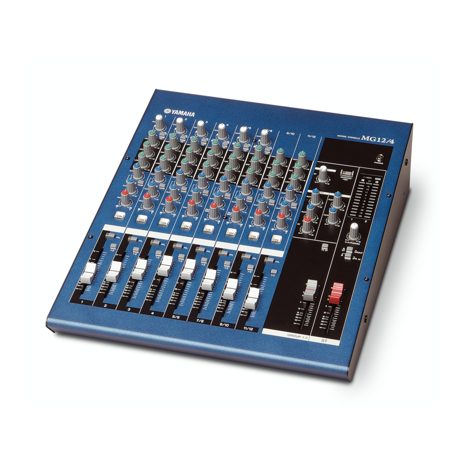
- Page 1 MIXING CONSOLE Owner’s Manual MG16/4 MG12/4 Making the Most Of Your Mixer Pages 6 to 17...
- Page 2 Never pull the cord. A damaged power cord is a potential fire and electrical shock hazard. Do not touch the power plug with wet hands. Doing so is a potential electrical shock hazard. MG16/4, MG12/4 Precautions —For safe operation— WARNING...
- Page 3 The wire which is coloured BROWN must be connected to the terminal which is marked with the letter L or coloured RED. Making sure that neither core is connected to the earth terminal of the three pin plug. • This applies only to products distributed by Yamaha-Kemble Music (U.K.) Ltd. (2 wires) Influence on cell phone usage Using a cell phone (mobile telephone) near this unit may induce noise.
-
Page 4: Table Of Contents
Thank you for your purchase of the YAMAHA MG16/4 or MG12/4 mixing console. This mixing console combines ease of operation with support for multiple usage environments, and is ideal for SR setups, installed systems, and many other such applications. Please read through this Owner’s Manual carefully before beginning use, so that you will be able to take full advantage of the mixer’s superlative features and enjoy trouble-free operation... -
Page 5: Before Turning On The Mixer
Note that trace current continues to flow while the switch is in the STANDBY position. If you do not plan to use the mixer again for a long while, please be sure to unplug the adaptor from the wall outlet. MG16/4, MG12/4... -
Page 6: Making The Most Of Your Mixer
Well, if you’ve done this before you won’t have any problems, but if this is the first time you’ve ever used a mixer you might want to read through this little tutorial and pick up a few basics that will help you get better performance and make better mixes. MG16/4, MG12/4... -
Page 7: Place For Everything And Everything In Its Place
Microphone cables usually have this type of connector, as do the inputs and outputs of most professional audio gear. Male Female Making the Most Of Your Mixer The Versatile Phone Jack Stereo/TRS phone plug Mono phone plug MG16/4, MG12/4... -
Page 8: How Do Balanced Lines Reject Noise
Normal-phase signal + normal-phase noise. Normal-phase signal + reverse-phase noise. MG16/4, MG12/4 Use balanced lines. Unbalanced lines are fine if you’re in a relatively noise-free environment. The ambient electromagnetic noise level will be the ultimate deciding factor, but balanced is best. - Page 9 –10 or +4 dB. Be sure to set these switches to match the level of the connected equipment. Inputs that feature a “Gain” control—such as the mono-channel inputs on your Yamaha mixer—will accept a very wide range of input levels because the control can be used to match the input’s sensi- tivity to the signal.
-
Page 10: Where Your Signal Goes Once It's Inside The Box
You can actually overload the input channel by applying too much EQ boost. It’s usually better to cut than boost. MG16/4, MG12/4 Input Channel Signals from the mixer’s other input channels (if they are assigned to this master output or “bus”). -
Page 11: Head Amplifier “Gain” Control Is Key
Just remember that too much initial gain is bad too, because it will over- load our channel circuitry and cause clipping. Making the Most Of Your Mixer MG16/4, MG12/4... - Page 12 “dynamic range” of your program material. MG16/4, MG12/4 Start by setting all level controls to their minimum: master fad- ers, group faders (if provided), channel faders, and input gain controls.
-
Page 13: External Effects, Monitor Mixes, And Groups
AUX send level control and the channel fader. Post-fader sends are most commonly used in conjunc- tion with the mixer’s AUX or effect returns for external effect processing. Master Fader MG16/4, MG12/4... -
Page 14: Using Groups
Channel faders Assigned to Group (Controlled As a Group) Channel faders Assigned to Stereo (Controlled Individually) MG16/4, MG12/4 A group of channels whose levels need to maintain the same relationship—a drum mix, for example—can be assigned to a group bus. -
Page 15: Channel Inserts For Channel-Specific Processing
“return” signal from the output of the pro- cessor. To the INSERT I/O jack Making the Most Of Your Mixer Channel Fader To the input jack of the external processor Sleeve Sleeve Ring To the output jack of the external processor MG16/4, MG12/4... -
Page 16: Making Better Mixes
Once again, there are no rules, but these are concepts that have been proven to work well. MG16/4, MG12/4 Music First—Then Mix In any case, the music comes first. Think about the music and let it guide the mix, rather than try- ing to do things the other way around. - Page 17 You don’t want reverb to dominate the mix unless you are trying to create the effect of a band in a cave—which is a perfectly legitimate creative goal if that’s the sort of thing you’re aim- ing for. MG16/4, MG12/4...
-
Page 18: Front & Rear Panels
3 dB below the clipping level. For XLR-equipped stereo input channels (9/10 and 11/12 on the MG16/4; 5/6 and 7/8 on the MG12/4), detects both post-EQ and post-mic-amp peak levels, and lights red if either of these levels reaches 3 dB below the clipping level. - Page 19 NOTE and BAL controls (9/10 and 11/12 on the MG16/4; 5/6 and 7/8 on the MG12/4), the knob operates as a PAN control if you are inputting through the MIC jack or into the L (MONO) input only, and operates as a BAL control if you are inputting into both L and R inputs.
-
Page 20: Master Control Section
This switch toggles phantom power on and off. If you set the switch on, the mixer supplies power to all channels that provide XLR mic input jacks (CHs 1–8, 9/10, 11/12 on MG16/4, 1–4, 5/6, 7/8 on MG12/4). Set this switch on when using one or more condenser microphones. NOTE ), the mixer sends the signals processed ) onto the Stereo bus. - Page 21 The signal monitored by these jacks is selected by NOTE the settings of the ST-GROUP toggle switch, the 2TR IN switch, and the PFL switches on the input channels. C-R OUT & PHONES ), then only the Front & Rear Panels MG16/4, MG12/4...
-
Page 22: Rear Input/Output Section
CHs 1 to 4, 5/6, 7/8) These are balanced XLR-type microphone input jacks (1:Ground; 2:Hot; 3:Cold). • LINE jacks (MG16/4: CHs 1 to 8. MG12/4: CHs 1 to 4) These are balanced TRS phone-type line input jacks (T: Hot; R: Cold; S: Ground). - Page 23 Pin 2: Hot (+) Pin 3: Cold (–) Tip: Hot (+) Ring: Cold (–) Sleeve: Ground Tip: Output Ring: Input Sleeve: Ground Tip: L Ring: R Sleeve: Ground Tip: Hot Sleeve: Ground Front & Rear Panels INPUT OUTPUT Ring Sleeve Sleeve MG16/4, MG12/4...
-
Page 24: Setting Up
LINE or MIC jack on the mixer. (LINE jacks on MG16/4: CHs 1 to 8; on MG12/4: 1 to 4. MIC jacks on MG16/4: CHs 1 to 8, 9/10, 11/12; on MG12/4: 1 to 4, 5/6.) -
Page 25: Sound Reinforcement For Live Performance
Monitor Speakers (Internal) Drums Power Amp Effector Microphones CD, Cassette, or DAT Synthesizer Recorder Bass CD Player Effector Guitar Microphones Power Amp Guitar Headphones Main Speakers (External) Example of Speaker Arrangement Stage (Internal) AUX 1 ( PRE Audience (External) MG16/4, MG12/4... -
Page 26: Rack Mounting
Do not install the mixer near power amps or other heat-generating devices. MG16/4, MG12/4 I Mounting the MG12/4 (1) Two metal rack-mount supports are screwed onto the unit. Use a screwdriver to remove these supports. (2) Turn the supports over, and fasten them into place again using the same screws. -
Page 27: Appendix
0.1 % (THD+N) @+14 dBu, 20 Hz–20 kHz, 600 (MG16/4 CH1-8, MG12/4 CH1-4) Equivalent input noise 150 –128 dBu MG12/4: CHs 1 to 4) –100 dBu Residual output noise (ST OUT) ST, GROUP Master fader at nominal level and all Ch –88 dBu (92 dB S/N) - Page 28 Where 0 dBu = 0.775 V and 0 dBV= 1 V Specifications and descriptions in this owner’s manual are for information purposes only. Yamaha Corp. reserves the right to change or modify products or specifications at any time without prior notice. Since specifications, equipment or options may not be the same in every locale, please check with your Yamaha dealer.
-
Page 29: Dimensional Diagrams
Dimensional Diagrams I MG16/4 H 108 101.3 I MG12/4 W 423 W 322 317.4 Appendix When mounted on rack When mounted on rack MG16/4, MG12/4... -
Page 30: Block Diagram And Level Diagram
Appendix Block Diagram and Level Diagram MG16/4, MG12/4... - Page 31 For details of products, please contact your nearest Yamaha representative or the authorized distributor listed below. Pour plus de détails sur les produits, veuillez-vous adresser à Yamaha ou au distributeur le plus proche de vous figurant dans la liste suivante.
- Page 32 Yamaha Manual Library http://www2.yamaha.co.jp/manual/english/ U.R.G., Pro Audio & Digital Musical Instrument Division, Yamaha Corporation © 2002 Yamaha Corporation V981800 312CRCR68.2-06D0 Printed in China...