Table of Contents
Advertisement
Advertisement
Table of Contents

Related Manuals for Yamaha MG 6FX


Summary of Contents for Yamaha MG 6FX
- Page 1 MIXING CONSOLE Owner’s Manual Making the Most Of Your Mixer Pages 6 to 18...
- Page 2 Installation Connect this unit’s AC power adaptor only to an AC outlet of the type stated in this Owner’s Manual or as marked on the unit. Failure to do so is a fire and electrical shock hazard. Do not allow water to enter this unit or allow the unit to become wet.
- Page 3 The above statements apply ONLY to those products distributed by Yamaha Corporation of America or its subsidiaries. * This applies only to products distributed by YAMAHA CORPORATION OF AMERICA. (class B) Connecting the Plug and Cord • This applies only to products distributed by Yamaha-Kemble Music (U.K.) Ltd. (2 wires).
-
Page 4: Table Of Contents
Thank you for your purchase of the YAMAHA MG16/6FX mixing console. This mixing console combines ease of operation with support for multiple usage environments, and is ideal for SR setups, installed systems, and many other such applications. Please read through this Owner’s Manual carefully before beginning use, so that you will be able to take full advantage of this mixer’s superlative features and enjoy trouble-free operation... -
Page 5: Before Turning On The Mixer
Before Turning on the Mixer (1) Be sure that the mixer’s power switch is in the STANDBY position. Use only the PA-30 adaptor included with this mixer. Use of a different adaptor may result in equipment damage, overheating, or fire. (2) Connect the power adaptor to the AC ADAPTOR IN con- nector ( ) on the rear of the mixer, and then turn the fas-... -
Page 6: Making The Most Of Your Mixer
Making the Most Of Your Mixer An Introduction You’ve got yourself a mixer and now you’re ready to use it. Just plug everything in, twiddle the controls, and away you go … right? Well, if you’ve done this before you won’t have any problems, but if this is the first time you’ve ever used a mixer you might want to read through this little tutorial and pick up a few basics that will help you get better performance and make better mixes. -
Page 7: Place For Everything And Everything In Its Place
A Place For Everything and Everything In Its Place 1-1. A Plethora Of Connectors—What Goes Where? Questions you’re likely to encounter when setting up a system for the first time might include “Why all these different types of connectors on the back of my mixer?” and “What’s the difference?”. Let’s start by taking a look at the most common connector types. -
Page 8: How Do Balanced Lines Reject Noise
Making the Most Of Your Mixer 1-2. Balanced, Unbalanced—What’s the Difference? In a word: “noise.” The whole point of balanced lines is noise rejection, and it’s something they’re very good at. Any length of wire will act as an antenna to pick up the random electromagnetic radiation we’re constantly surrounded by: radio and TV signals as well as spurious electromagnetic noise generated by power lines, motors, electric appliances, computer monitors, and a variety of other sources. - Page 9 –10 or +4 dB. Be sure to set these switches to match the level of the connected equipment. Inputs that feature a “Gain” control—such as the mono-channel inputs on your Yamaha mixer—will accept a very wide range of input levels because the control can be used to match the input’s sensi- tivity to the signal.
-
Page 10: Where Your Signal Goes Once It's Inside The Box
Making the Most Of Your Mixer Where Your Signal Goes Once It’s Inside the Box At first glance the block diagram of even a modest mixer can look like a space-station schematic. In reality, block diagrams are a great aid in understanding how the signal flows in any mixer. Here’s a greatly simplified block diagram of a generic mixer to help you become familiar with the way these things work. -
Page 11: The First Steps In Achieving Great Sound
The First Steps in Achieving Great Sound Before you even consider EQ and effects, or even the overall mix, it is important to make sure that levels are properly set for each individual source. This can’t be stressed enough—initial level setup is vitally important for achieving optimum performance from your mixer! Here’s why …... - Page 12 Making the Most Of Your Mixer 3-2. Level Setup Procedure For Optimum Performance Now that we know what we have to do, how do we do it? If you take another quick look at the mixer block diagram you’ll notice that there’s a peak indicator located right after the head amplifier and EQ stages, and therein lays our answer! Although the exact procedure you use will depend on the type of mixer you use and the application, as well as your personal preferences, here’s a general outline: That’s basically all there is to it.
-
Page 13: External Effects, Monitor Mixes, And Groups
External Effects, Monitor Mixes, and Groups 4-1. AUX Buses For Monitor Sends and Overall Effects There are a number of reasons why you might want to “tap” the signal flowing through your mixer at some point before the main outputs: the two most common being 1) to create a monitor mix that is separate from the main mix, and 2) to process the signal via an external effect unit and... -
Page 14: Using Groups
Making the Most Of Your Mixer 4-2. Using Groups Group buses and faders can greatly simplify the mixing process—particularly in live situations in which changes have to be made as quickly as possible. If you have a group of channels that need to be adjusted all together while maintaining their relative levels, grouping is the way to go. -
Page 15: Channel Inserts For Channel-Specific Processing
4-3. Channel Inserts for Channel-specific Processing Another way to get the mixer’s signal outside the box is to use the channel inserts. The channel inserts are almost always located before the channel fader and, when used, actually “break” the mixer’s internal sig- nal path. -
Page 16: Making Better Mixes
Making the Most Of Your Mixer Making Better Mixes 5-1. Approaching the Mix—Where Do You Start? Mixing is easy, right? Just move the faders around until it sounds right? Well, you can do it that way, but a more systematic approach that is suited to the material you’re mixing will produce much better results, and faster. - Page 17 5-2. Panning For Cleaner Mixes Not only does the way you pan your individual channels determine where the instruments appear in the stereo sound field, but it is also vital to give each instrument it’s own “space” so that it doesn’t conflict with other instruments.
- Page 18 Making the Most Of Your Mixer 5-4. Ambience Judicious application of reverb and/or delay via the mixer’s AUX busses can really polish a mix, but too much can “wash out” the mix and reduce overall clarity. The way you set up your reverb sound can make a huge difference in the way it meshes with the mix.
-
Page 19: Front & Rear Panels
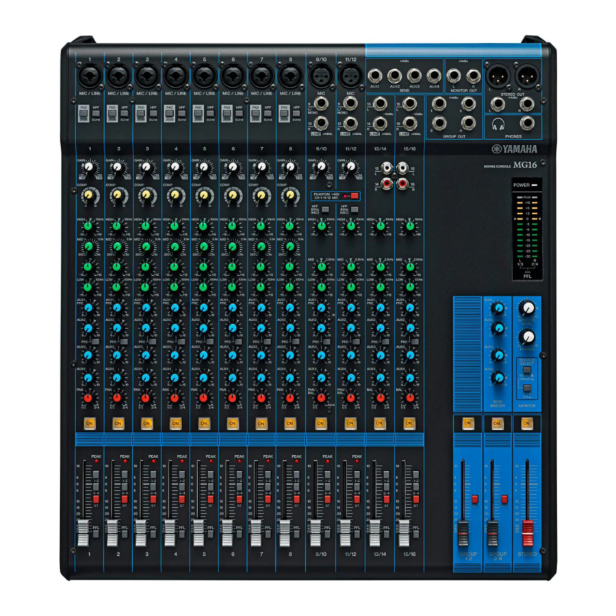
Front & Rear Panels Channel Control Section Channels Channels Channels 1 to 8 9/10 and 11/12 13/14 and 15/16 (Monaural) (Stereo) (Stereo) 1 GAIN Control Adjusts the input signal level. To get the best balance between the S/N ratio and the dynamic range, adjust the level so that the peak indicator ( ) comes on only at about maximum input level. - Page 20 Front & Rear Panels 5 AUX1 and AUX2 Controls The AUX1 knob controls the signal level that the channel sends to the AUX1 bus; the AUX2 knob controls the signal level to the AUX2 bus. These knobs should generally be set close to the position.
-
Page 21: Master Control Section
Master Control Section 1 ST Master Fader Adjusts the signal level to the ST OUT jacks. 2 GROUP Faders (1-2, 3-4) Adjust the signal level to the GROUP OUT 1 to 4 jacks. 3 TO ST Switch If this switch is on ( by the GROUP faders ( signal go to Stereo L and the Group 2/4 signal go to Stereo R. - Page 22 Front & Rear Panels 8 Level-Meter Signal Switches These level-meter switches, together with the channel PFL switches, select the signal that is sent through the C-R/PHONES control to the C-R OUT jacks, the PHONES jack, and the level meter. The following illustration shows how the switch settings corre- spond to the signal selection.
-
Page 23: Rear Input/Output Section
Rear Input/Output Section 1 Channel Input Jacks • MIC jacks (CHs 1 to 8, 9/10, 11/12) These are balanced XLR-type input jacks. • LINE jacks (CHs 1 to 8) These are balanced phone-type input jacks. You can connect either balanced or unbalanced phone plugs to these jacks. Where an input channel provides both a MIC jack NOTE and a LINE jack, you may use either one of these... - Page 24 Front & Rear Panels 6 C-R OUT Jacks These are impedance-balanced phone-type output jacks. These jacks output the mixed signal whose level is adjusted by the C-R/PHONES control. Output is in stereo (L and R). These jacks are typically used to connect to a monitor system. The signal monitored by these jacks is selected by NOTE the Level-Meter Signal switches and the channel...
-
Page 25: Setting Up
Setup Procedure (1) Before connecting to microphones and instruments, be sure that all devices are turned off. Also be sure that all of the mixer’s channel faders and master control faders are set all the way down. (2) For each connection, connect one end of the cable to the rele- vant microphone or instrument and connect the other end to the appropriate LINE or MIC jack on the mixer. -
Page 26: Sound Reinforcement For Live Performance
Setting Up I Sound Reinforcement for Live Performance Monitor Speakers (Internal) Power Amp CD, Cassette, or DAT Power Amp Main Speakers (External) MG16/6FX Drums Effector Microphones Recorder CD Player Synthesizer Bass Effector Guitar Microphones Guitar Headphones Example of Speaker Arrangement Stage (Internal) AUX 1 Audience (External) -
Page 27: Rack Mounting
Rack Mounting I Mounting (1) Two metal rack-mount supports are screwed onto the unit. Use a screwdriver to remove these supports. (2) Turn the supports over, and fasten them into place again using the same screws. (3) Mount the unit into the rack, and fasten it into place. If you wish you may move the left support to the NOTE right side and the right support to the left side, as... -
Page 28: Appendix
Specifications I General Specifications Frequency Characteristics (ST OUT) Total Harmonic Distortion (ST OUT) Hum and Noise Maximum Voltage Gain Monaural/Stereo Input Gain Control Monaural/Stereo High Pass Filter Crosstalk (1 kHz) Monaural Input Channel Equalization: Max. Variation (CHs 1 to 8) Stereo Input Channel Equalization: Max. - Page 29 Where 0 dBu = 0.775 V and 0 dBV= 1 V Specifications and descriptions in this owner’s manual are for information purposes only. Yamaha Corp. reserves the right to change or modify products or specifications at any time without prior notice. Since specifications, equipment or options may not be the same in every locale, please check with your Yamaha dealer.
-
Page 30: Dimensional Diagrams
Appendix Dimensional Diagrams W 423 When mounted on rack MG16/6FX H 108 101.3 Unit: mm... -
Page 31: Block Diagram And Level Diagram
Appendix Block Diagram and Level Diagram MG16/6FX... - Page 32 Pour plus de détails sur les produits, veuillez-vous adresser à Yamaha ou au distributeur le plus proche de vous figurant dans la liste suivante. NORTH AMERICA CANADA Yamaha Canada Music Ltd. 135 Milner Avenue, Scarborough, Ontario,...