
Related Manuals for Yamaha MG Series


Summary of Contents for Yamaha MG Series
- Page 1 Owner’s Manual Precautions pages 5, 6 Quick Start Guide pages 9 to 11 Troubleshooting pages 29 to 31...
- Page 3 Explanation of Graphical Symbols Explication des symbols The lightning flash with arrowhead symbol within an equilateral triangle is intended to alert the user to the presence of uninsulated “dangerous voltage” within the product’s enclosure that may be of sufficient magnitude to constitute a risk of electric shock to per- sons.
- Page 4 If these corrective measures do not produce satisfactory results, please contact the local retailer authorized to distribute this type of product. If you cannot locate the appropriate retailer, please contact Yamaha Corporation of America, 6600 Orangethorpe Ave., Buena Park, CA90620, USA.
-
Page 5: Precautions
• When one of the following problems occur, immediately turn PLEASE READ CAREFULLY off the power switch and disconnect the electric plug from the outlet. Then have the device inspected by Yamaha BEFORE PROCEEDING service personnel. - The power cord or plug becomes frayed or damaged. - Page 6 • Avoid inserting or dropping foreign objects (paper, plastic, metal, etc.) into any gaps or openings on the device (vents). Yamaha cannot be held responsible for damage caused If this happens, turn off the power immediately and unplug by improper use or modifications to the device, or data the power cord from the AC outlet.
-
Page 7: Table Of Contents
Thank you for purchasing the Yamaha MG20XU/MG20/MG16XU/MG16X/ MG16/MG12XU/MG12X/MG12 mixing console. Please read this manual thor- oughly to get the most out of the product and ensure long-term, trouble-free use. After reading this manual, please keep it available for future reference. -
Page 8: Main Features
Improved Convenience with Built-in Universal Switching Power Supply The MG series features a universal switching power supply. This power supply supports input voltages of 100 V to 240 V, for stable operation even in environments where power voltage fluctuates easily. Lowering the impedance of the power sup- ply has resulted in improved sound quality with a faster attack. -
Page 9: Quick Start Guide
Quick Start Guide We’ll begin this guide by connecting a pair of speakers and generating some stereo output. Note that the operations and procedures will vary somewhat according to the input devices you are using. • Power switch (rear panel) •... -
Page 10: Step 4 Getting Sound To The Speakers
Quick Start Guide Step 4 Getting Sound to the Speakers [PHONES] jack [GAIN] knobs Level meter [PEAK] indicator Level meter [PFL] indicator [PHONES] knob Channel [ON] switches [STEREO] master [ON] switch Channel [ST] switches [STEREO] master fader Channel [PFL] switches Channel faders Turn on ( ) the [PFL] switches for each chan-... -
Page 11: Step 5 Using The Built-In Effects (Xu Models And X Models)
Quick Start Guide Step 5 Using the Built-in Effects (XU Models and X Models) Display [PROGRAM] knob* [PARAMETER] knob* [AUX (2, 4)/FX] knobs [ON] switch for [FX RTN] [ST] switch for [FX RTN] * The [PROGRAM] knob and [PARAMETER] knob on the MG20XU are in slightly different [FX RTN] fader locations than shown here. -
Page 12: Setup
Mono input jacks accept both XLR connectors and phone connectors. Rear Panel Computer (for music Foot switch playback and/or recording) (Yamaha FC5) (The [FOOT SW] jack is on XU models and X models.) (The [USB 2.0] jack is on XU models only.) - Page 13 Setup 2. For Events and Parties Front Panel Microphones DVD player (voice) Powered speakers DJ mixer Headphones Rear Panel CD player Computer (for music playback and/or recording) Power amp (The [USB 2.0] jack is on XU models only.) Speakers NOTE On the MG20XU/MG20, the [SEND] jack, [GROUP OUT] jack, [MONITOR OUT], jack, and [STEREO OUT] jack are located on the rear panel.
-
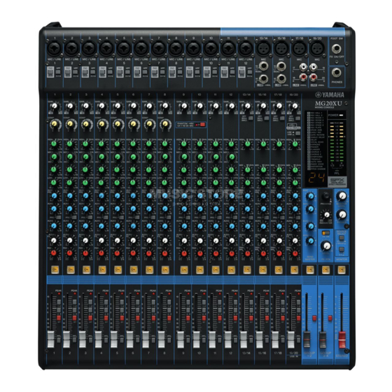
Page 14: Controls And Connectors
Controls and Connectors Front Panel The number and locations of jacks and controls vary slightly by model. Carefully check the name indicated near each jack and control while referring to this manual. Mono input channels (page 16) Mono/stereo input channels (page 16) Stereo input channels (page 16) Master block jacks (page 24) -
Page 15: Rear Panel
Controls and Connectors Rear Panel MG16XU Power Block (page 27) USB Block (XU models only) (page 28) MG20XU Master block jacks (page 24) Master Block The master block jacks on the MG20XU/MG20 are all located on the rear panel, except the [PHONES] jack. MG20XU/MG20/MG16XU/MG16X/MG16/MG12XU/MG12X/MG12 Owner’s Manual... -
Page 16: Input Channel Block
Controls and Connectors q Mono input jacks Input Channel Block MG20XU/MG20: 1 – 12 Mono input Mono/stereo input Stereo input MG16XU/MG16X/MG16: 1 – 8 channels channels channels MG12XU/MG12X/MG12: 1 – 4 1 – 12 13/14 – 19/20 (MG20XU/MG20) (MG20XU/MG20) 1 – 8 9/10 –... - Page 17 Controls and Connectors r [PAD] switch u [COMP] knobs For adjusting the amount of compression applied to the chan- When this switch is turned on ( ), the input signal from nel. As the [COMP] knob is turned to the right the threshold, the [MIC/LINE] jack of the mono input channel is attenuated ratio, and output gain are adjusted simultaneously.
- Page 18 Controls and Connectors !0 Equalizer ([HIGH]/[MID]/[LOW]) !1 [AUX 1 – 4] knobs [PRE] switches [AUX (2, 4)/FX] knobs MG20XU/MG16XU/MG16X: [AUX1], [AUX2 – 3], [AUX4/FX] MG20/MG16: [AUX1], [AUX2 – 4] MG12XU/MG12X: [AUX1], [AUX2/FX] MG12: [AUX1 – 2] The levels of each signal sent to the AUX 1 – 4 buses from each channel can be adjusted independently.
- Page 19 Controls and Connectors • BAL: Sets the volume balance of the signal sent from These switches determine the bus(es) to which each channel’s each stereo input channel (L/R) to the STEREO signal is sent. Turn the switch on ( ) to output the signal to L/R bus or GROUP bus.
- Page 20 Controls and Connectors Mono input channels MG20XU/MG20 : CH1–12 MG16XU/MG16X/MG16 : CH1–8 MG12XU/MG12X/MG12 : CH1–4 (*) Only MG20XU, MG20, MG16XU, MG16X and MG16 PHANTOM MG20XU/MG20 : CH1–8 PEAK MG16XU/MG16X/MG16 : CH1–8 PAD OFF MG12XU/MG12X/MG12 : CH1–4 [-60dBu – -16dBu] ON (CH Fader) 3-4 (*) PAD ON...
- Page 21 Controls and Connectors Stereo input channels MG16XU/MG16X/MG16 : CH13/14,15/16 MG12XU/MG12X/MG12 : CH9/10,11/12 (*) Only MG16XU, MG16X and MG16 MG16XU : CH13/14 MG16X/MG16 : CH13/14,15/16 MG12XU : CH9/10 (ST CH Fader) 3-4 (*) MG12X/MG12 : CH9/10,11/12 L [-10dBu] MG12XU/MG12X/MG12 AUX1 MG16XU/MG16X/MG16 : 3-Stage USB-PLAY-L...
-
Page 22: Built-In Effects Block
Controls and Connectors q Display Built-in Effects Block (XU Models and X Models) MG20XU/MG16XU/MG16X : AUX4/FX MG12XU/MG12X : AUX2/FX Indicates the effect program number selected with the [PRO- (*) Only MG16XU and MG16X MG16XU/MG16X GRAM] knob e. The number flashes during selection; how- MG12XU/MG12X USB-Att. - Page 23 Bus assign switch (MG16XU/MG16X/MG12XU/MG12X) Connect a foot switch to this phone type input jack. An optional Yamaha FC5 foot switch (sold separately) can be used to toggle the effects ON and OFF. MG16XU/MG16X MG12XU/MG12X...
-
Page 24: Master Block
Controls and Connectors q [SEND] jacks Master Block MG20XU/MG20/MG16XU/MG16X/MG16: [AUX1 – 4] MG12XU/MG12X/MG12: [AUX1 – 2] You use these jacks, for example, to connect to an external effect device or a stage/studio monitoring system. These are impedance-balanced* phone-type output jacks. * Impedance-balanced Since the hot and cold terminals of impedance-balanced output jacks have the same impedance, these output jacks... - Page 25 Controls and Connectors r [STEREO OUT] jacks • [POWER] indicator This indicator lights up when the mixer’s power is on • Level meter The level meter LED shows the level of the signal in the STEREO L/R and GROUP buses, or selected with [PFL] switches.
- Page 26 Controls and Connectors u [SEND MASTER] section i [GROUP] section (*) Only MG20XU, MG20, MG16XU, MG16X and MG16 (*) Only MG20XU, MG20, MG16XU, MG16X and MG16 AUX1 G1 MONI SEND AUX1 G2 MONI [+4dBu] GROUP 1-2 AUX2 GROUP OUT 1 SEND AUX2 [+4dBu] [+4dBu]...
-
Page 27: Power Block
Controls and Connectors o [STEREO] section Power Block • ] POWER switch USB-REC-L STL MONI USB-REC-R STR MONI STEREO OUT L STEREO [+4dBu] Turns power to the unit on or off. Press the switch to the “ ” position to turn on the power. Press the switch to the STEREO OUT R “... -
Page 28: Usb Block (Xu Models Only)
You can down- dB. (The minus sign is not displayed.) load the driver from the following Yamaha website, and install it on your computer. 3. Press the [PROGRAM] knob again to exit the setting. -
Page 29: Troubleshooting
Troubleshooting When No Sound Is Output Refer to this section when no sound is output or the volume is very low. This information is for when sound is output from the [STEREO OUT] jacks or the [PHONES] jack. For details about these functions, see “Controls and Connectors” on pages 14 – 28. ... - Page 30 Troubleshooting STEP 2 Setting Switches and Controls Check the overall balance Use the settings shown in the illustration to check the overall balance from speakers or headphones. [GAIN] knobs [PHANTOM +48V] switch Turn until the [PEAK] indi- Turn this switch on (the indicator lit) when using a condenser microphone. cator begins to flash inter- •...
-
Page 31: Other
Use the “Attenuator Function” . For details, see page 28. The volume of audio play- back from a computer need to be adjusted. If any specific problem should persist, please contact your Yamaha dealer. MG20XU/MG20/MG16XU/MG16X/MG16/MG12XU/MG12X/MG12 Owner’s Manual... -
Page 32: Appendix
0 to + 40°C For other specifications, see the included “Technical Specifications.” The contents of this manual apply to the latest specifications as of the publishing date. To obtain the latest manual, access the Yamaha web- site then download the manual file. -
Page 33: Effect Programs
Appendix Effect Programs Program Parameter Description REV HALL 1 Reverb Time Reverb simulating a large space such as a concert hall. REV HALL 2 Reverb Time REV ROOM 1 Reverb Time Reverb simulating the acoustics of a small space (room). REV ROOM 2 Reverb Time REV STAGE 1... -
Page 34: Jack And Connector List
Appendix Jack and Connector List Jacks and Connectors Polarities Configurations INPUT OUTPUT Pin 1: Ground MIC/LINE, MIC, STEREO OUT Pin 2: Hot (+) Pin 3: Cold (–) XLR Jack MIC/LINE*, AUX SEND, Tip: Hot (+) Ring GROUP OUT, MONITOR OUT, Ring: Cold (–) STEREO OUT Sleeve: Ground... -
Page 35: Rack Mounting
Appendix Mounting Procedures Rack Mounting (The illustration shows the MG12XU.) The MG12XU/MG12X/MG12 require at least 10 U* of rack space. To take into account the cable connections, we recommend Use a screwdriver to loosen the screws on the to ensure 11 U* of rack space. The MG20XU/MG20/MG16XU/ sides of the mixer (six total). -
Page 36: Index
Appendix Index Numerics [1-2] switch ............19, 23 [ON] switch .......... 19, 23, 26, 27 [3-4] switch ............19, 23 [PAD] switch ............17 [AC IN] jack ............27 [PAN] knob ............18 Attenuator Function ..........28 [PAN/BAL] knob ............ 18 [AUX1] knob ............23 [PARAMETER] knob .......... - Page 37 MEMO MG20XU/MG20/MG16XU/MG16X/MG16/MG12XU/MG12X/MG12 Owner’s Manual...
- Page 38 MG20XU/MG20/MG16XU/MG16X/MG16/MG12XU/MG12X/MG12 Owner’s Manual...
- Page 39 Head Office/Manufacturer: Yamaha Corporation 10-1, Nakazawa-cho, Naka-ku, Hamamatsu, 430-8650, Japan PA57 Importer (European Union): Yamaha Music Europe GmbH Siemensstrasse 22-34, 25462 Rellingen, Germany Importer (United Kingdom): Yamaha Music Europe GmbH (UK) Sherbourne Drive, Tilbrook, Milton Keynes, MK7 8BL, United Kingdom...
- Page 40 Yamaha Pro Audio global website http://www.yamahaproaudio.com/ Yamaha Downloads https://download.yamaha.com/ Manual Development Group © 2021 Yamaha Corporation Published 11/2021 POEM-A0 VFN3500...