
Related Manuals for Comelit 8461V


Summary of Contents for Comelit 8461V
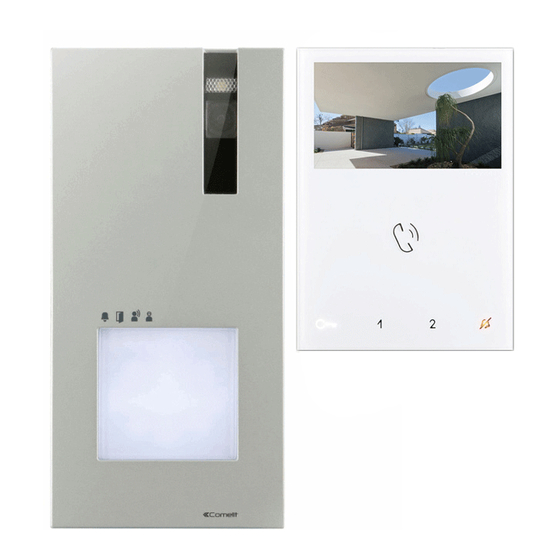
- Page 1 TECHNICAL MANUAL Technical manual for single-family KIT Art. 8461V Passion.Technology. Design.
-
Page 2: Warning
Do not tamper with the internal elements offering protection against short circuits and overcurrents. • All the equipment must only be used for the purpose it was designed for. Comelit Group S.p.A. declines any responsibility for improper use of the apparatus, for any alterations made by others for any reason or for the use of non-original accessories or materials. -
Page 3: Table Of Contents
External unit settings ................10 and switching device Art. 1404 .............33 Call address programming for 2-4 users Wiring diagram for system with 2 single-family KITS KIT 8461V and additional external unit ..............11 and main external unit Art. 4893 ............34 Programming a generic call address ...........12 KIT 8461V: additional actuator relay Art. -
Page 4: Package Contents
• Sluit de voeding af voordat u onderhoudswerkzaamheden uitvoert. • All the equipment must only be used for the purpose it was designed for. Comelit • Installeer de camera niet tegenover felle lichtbronnen of op plaatsen waar de Group S.p.A. -
Page 5: Operating Distances
1209 1214/2C 1209 4893 4893 A MAX B MAX Comelit Art. 4577/4579 1 mm2 (Ø 1,2 mm AWG 17) 200 m 100 m (655 feet) (330 feet) UTP5 cat. 5 0,2 mm2 (Ø 0,5 mm AWG 24) 100 m 60 m... -
Page 6: Power Supply Unit Art. 1209
Power supply unit Art. 1209 Description 31 Vdc power supply unit for 2-wire KIT, for direct connection to the external unit and internal unit. Equipped with overload and short circuit protection. Input voltage 110-240 VAC. Dimensions: 108x90x62 mm (6 DIN modules). Dopo un cortocircuito,per ripristinare l'apparecchio, interrompere l'alimentazione per circa 1 minuto. -
Page 7: External Unit Art. 4893
External unit Art. 4893 Description Wall-mounted external unit for Quadra series door entry monitor. Die-cast aluminium front panel, wide-angle colour camera and single LED for lighting at night. Capacitive buttons with the option of setting 1 to 4 call buttons via dip switch. Indicator LED for call sent, lock-release activated, audio activated and system busy. -
Page 8: Installation
Installation OPEN CAUTION! Tighten properly to avoid leaks optional... - Page 9 You can download the free software (Art. 1235A) from the website www.comelitgroup.com to print the entrance panel name tags, using the adhesive pre-cut sheets available in our catalogue (Art. 1217) REMOVE JOHN SMITH MAKE SURE THE POSITIONING IS PETER WHIT CORRECT BEFORE GLUEING THE NAMES IN PLACE...
-
Page 10: External Unit Settings
External unit settings f Set the DIP-switches of S1 corresponding to the function that you want to programme as shown in the table below DIP 1 DIP 2 DIP 3 DIP 4 DIP 5 DIP 6 DIP 7 DIP 8 The lock- lock-release relay activation... -
Page 11: Call Address Programming For 2-4 Users And Additional External Unit
Call address programming for 2-4 users and additional external unit √ Take note of the DIP-switch settings. example: NOTE Fig. 3 - On the DIP-switch, set the code corresponding to the function you want to program as shown in the table on page 11. Reset the configuration of the DIP-switches of S1 Code Dip-Switch ON... -
Page 12: Programming A Generic Call Address
Programming a generic call address √ Take note of the DIP-switch settings. example: NOTE Fig. 3 - Set the user code on Dip Switches S1 (see table A on page 13). Reset the configuration of the DIP-switches of S1... -
Page 13: Riser Addresses
Riser addresses TAB. A Dip switch Dip switch Dip switch Dip switch Dip switch Dip switch Dip switch Dip switch Code Code Code Code Code Code Code Code 1,2,3,4,5 1,3,4,5,6 1,2,4,5,7 1,4,5,6,7 1,2,3,5,8 1,3,5,6,8 1,2,5,7,8 2,3,4,5,6 3,4,5,7 2,4,5,6,7 4,5,8 2,3,5,6,8 3,5,7,8 1,2,3,4,5,6 1,3,4,5,7... -
Page 14: Description Of Monitor Art. 6721W
Description of Monitor Art. 6721W 1. Brightness control f To increase the value, turn clockwise 2. Loudspeaker volume control f To increase the value, turn clockwise 3. 4.3’’LCD colour screen 4. Call volume adjustment (high - medium - low) 5. Soft-touch keys 6. -
Page 15: Soft-Touch Key Description
Soft-touch key description f Press the desired key once to activate the function associated with it Wait for approximately 1 sec. before pressing the same key again. Pressing the same key several times in quick succession will cancel the command. Lock-release key Key 1 Actuator function (programmable) Key 2 Self-ignition function (programmable) -
Page 16: Installation
Installation 115 mm optional fixing... -
Page 17: Removing / Fitting The Terminal
Removing / Fitting the terminal Fitting upgrade KIT Art. 6734W (to remove) -
Page 18: Operation
Operation Answer incoming call Press the soft-touch audio activation key to answer incoming call. Activation/deactivation automatic answer mode f Press on the audio activation key for 10 sec » (ACTIVATION) + audio LED with FIXED ILLUMINATION » (DEACTIVATION) + audio LED OFF Monitor configuration Standard configuration for soft-touch keys DIP S2... -
Page 19: Advanced Monitor Configuration
Advanced monitor configuration Warning If the default settings (see table on page 18) do not reflect requirements, the keys can be programmed differently by carrying out the steps below. At the end, set S2 DIP switches 1-2-3-4 to the combination 1111 (PROG setting in the configuration tables on pages 19-23). -
Page 20: Programming Buttons For Intercom Call
Programming buttons for intercom call DIP S2 Art. 6721W(/BM) + Art. 6734 DIP S1 DIP 1 DIP 2 DIP 3 DIP 4 INTb INTb INTb ADDRESS INTb INTb INTb PROG Example 1 - General intercom on a monitor with user code 5, P3 programming = general internal call, P4 = general intercom with address 9 Example 2 - Selective intercom on a monitor with user code 1 and intercom address 1, P3 programming = selective intercom with address 2, P4 = selective intercom with address 3... -
Page 21: Direct Programming Of Intercom Call
Direct programming of intercom call Allows direct programming of intercom call via the internal units. √ Requires 2 operators Step 1: enter programming mode Operator 1 and Operator 2 carry out the following procedures on 2 internal units: 1. Set S2 DIP switches 1-2 -3-4 to the combination 1111 2. -
Page 22: Programming Keys For Generic Or Coded Actuator
Programming keys for generic or coded actuator DIP S2 Art. 6721W(/BM) + Art. 6734 DIP S1 DIP 1 DIP 2 DIP 3 DIP 4 ADDRESS PROG Example: on a monitor with user code 5, P1 programming = generic actuator, P2 = coded actuator (code 125) Take note of the DIP-switch settings 1. -
Page 23: Programming Buttons For Other Functions
Programming buttons for other functions DIP S2 Art. 6721W(/BM) + Art. 6734 DIP 1 DIP 2 DIP 3 DIP 4 PROG Legend Lock- release Self-ignition Guardian doorentry phone call Doctor PROG Programmed functions Example: on a monitor with user code 5, P1 programming = self-ignition, P2= Doctor. 1. -
Page 24: Programming Range
Programming range Take note of the S2, S1 setting and restore it when programming is complete Carry out steps 1 to 4 S2 DIP Range minimum 1 2 3 4 5 6 address 0 0 0 0 1 0 set code, TAB. A on page Range maximum address... -
Page 25: Programming Reset
Programming reset Factory settings: • Button functions for the S2 DIP switch 1-2-3-4 combination; • Intercom address absent; • Range function and min./max. addresses absent; DIP OFF • Ringtone reset. Take note of the S2, S1 setting and restore it when programming is complete S2 DIP DIP ON 1 2 3 4 5 6... -
Page 26: Operation
Operation To make a call from an external unit f To send the call from an external unit, touch the button corresponding to the user you want to contact. If the system is not busy: on the external unit the caller illumination LED will light up, the LED will flash and the confirmation tone will sound. -
Page 27: Additional Door-Entry Phones Art. 2638
OPERATION WITH SWITCHING DEVICE ART. 1404 (DEFAULT) In the configuration of Art. 1404, the MIN and MAX Dip switches define respectively the lowest and highest user codes which can be connected to the riser. For information on setting the desired values, refer to the table on page 13. Separate switching devices for different risers must manage code ranges which are not overlapping. -
Page 28: Installation Of Door-Entry Phone Art. 2638
Installation of door-entry phone Art. 2638 Programming of door-entry phone Art. 2638 Set the user code on Dip Switches U2 as indicated in the table on page 13. -
Page 29: Wiring Diagrams
Wiring diagrams KIT 8461V: standard single-family system. Switching on/voltage check with system in standby 6721W 6721W/BM 1234 67 110-240V 30 Vdc 30 Vdc 1209 Local lock release button. 4893 MNVK/039QC... -
Page 30: Kit 8461V: Expansion For Two-Family System
KIT 8461V: expansion for two-family system 1216 6721W 6721W/BM +6710 1214/2C 6721W 6721W/BM 1234 67 1234 67 1214/2C 110-240V 1209 4893 8461V Additional monitors Art. 6721W/BM do not include a backplate. To program the special function “buttons 1-2 enabled with call addresses 1-2” see page 11. -
Page 31: Kit 8461V: Expansion For 4-User System
KIT 8461V: expansion for 4-user system 1216 6721W 6721W/BM +6710 1214/2C 1234 67 6721W 6721W/BM +6710 1234 67 1214/2C 6721W 6721W/BM +6710 1214/2C 1234 67 6721W 6721W/BM 1234 67 1214/2C Additional monitors Art. 110-240V 6721W/BM do not include a backplate. -
Page 32: Kit 8461V: Expansion With Second External Unit 4893 And Switching Device Art. 1405
KIT 8461V: expansion with second external unit 4893 and switching device Art. 1405 6721W 6721W/BM 1234 67 1209 L1 L1 L2 L2 110-240V 1405 4893 4893 SLAVE MAIN 8461V To program the special functions “Main external unit (Porter)” and “Secondary external unit (Porter)”, see page 11. -
Page 33: Kit 8461V: Expansion With 3 External Units 4893 And Switching Device Art. 1404
KIT 8461V: expansion with 3 external units 4893 and switching device Art. 1404 6721W 6721W/BM 1234 67 1404 1404 110-240V 110-240V 110-240V 1209 1209 1209 4893 4893 4893 8461V Local lock release button. The function “External unit (Porter) with switching (secondary)” is active by default (see Operation section, page 26). -
Page 34: Wiring Diagram For System With 2 Single-Family Kits Kit 8461V And Main External Unit Art. 4893
Wiring diagram for system with 2 single-family KITS KIT 8461V and main external unit Art. 4893 1216 1216 6721W 6721W 6721W/BM 6721W/BM 1234 67 1234 67 1214/2C 1214/2C 1404 1404 110-240V 110-240V 110-240V 1209 1209 1209 4893 4893 4893 8461V 8461V To program the special function “buttons 1-2 enabled with call addresses 1-2”... -
Page 35: Kit 8461V: Additional Actuator Relay Art. 1256
KIT 8461V: additional actuator relay Art. 1256 6721W 6721W/BM 1234 67 1200 1256 12V~ 230V~ 12/24V AC/DC 1214/2C 110-240V For further information see the respective 1209 manual. Local lock release button. 4893 8461V MNVK/EQC... -
Page 36: Kit 8461V: Additional Remote Camera Module Art. 1409
KIT 8461V: additional remote camera module Art. 1409 6721W 6721W/BM 1234 67 110-240V 1209 1409 1200 12V~ 230V~ IN IN 1234 67 4893 8461V To be powered separately. For the setting and operation of Art.1409 see the respective manual. Local lock release button. -
Page 37: Kit 8461V: Additional 2 Secondary Monitors In Cascade Connection
KIT 8461V: additional 2 secondary monitors in cascade connection 6721W 6721W 6721W 6721W/BM 6721W/BM 6721W/BM +6710 +6710 1234 67 1234 67 1234 67 1209 Additional monitors Art. 6721W/BM do not include a backplate. MNVK/Q23 Connection diagram for two-family system with one main monitor and 2 secondary... -
Page 38: Connection Diagram For System With Maximum Expansion In Branch Connection For Single Call Address
Connection diagram for system with maximum expansion in branch connection for single call address 6721W 6721W 1216 6721W/BM 6721W/BM +6710 +6710 1234 67 1234 67 1234 67 1214/2C 6721W 6721W 6721W/BM 6721W/BM +6710 1234 67 1234 67 1234 67 1214/2C 1209 Additional monitors Art. -
Page 39: Connection Diagram For Branch Connection From Riser Of Additional Door-Entry Phones Art. 2628/2638 And Art. 6228(B)(W)
Connection diagram for branch connection from riser of additional door-entry phones Art. 2628/2638 and Art. 6228(B)(W) 6721W 6721W/BM 1214/2C 2628/ 2638 1214/2C 6228B 6228W 1214/2C 2610 1214/2C S2 S1 1209 MNVK/FC Door open indication use variant 110-240V 1209 active input closed for DOOR OPEN signal. -
Page 40: Variant With Security Door Lock And Additional Power Supply
Variant with security door lock and additional power supply 12/24V AC/DC Local lock release button. 4893 SB2/SNPQ Floor door call connection variant If there are a number of door-entry phones or monitor brackets with the same user code, connect the CFP button to one only;... - Page 42 w w w . c o m e l i t g r o u p . c o m Via Don Arrigoni, 5 - 24020 Rovetta (BG) - Italy...