Table of Contents
Advertisement
Quick Links
Service Instructions
®
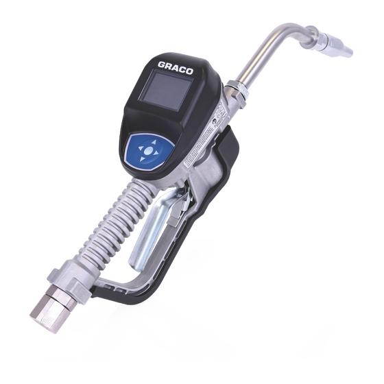
Pulse
, SDP and SDM Metered
Dispense Valve Repair
For dispensing oil, automatic transmission fluid (ATF), gear oils, antifreeze and
windshield washer solvent.
Not approved for use in explosive atmospheres or hazardous locations. For professional
use only.
Metered Dispense Valve Models: (page 5)
1500 psi (10 MPa, 103 bar) Maximum Working Pressure
Repair Kits
26C287: Pulse Bezel Replacement, page 8
26C403: SDP8/18 Bezel Replacement,
page 8
26C484: SDM8 and SDM18 Bezel
Replacement, page 8
25D906: Swivel Seal and Filter
Replacement, page 12
25D903: Trip Rod Replacement for Pulse
and SDP meters, page 15
26C394: Trip Rod Replacement for SDM8
and SDM18 meters, page 17
25D904: Valve Replacement, page 19
25P665: Power Cable Replacement, page
11
Important Safety
Instructions
Read all warnings and instructions
in this manual and related Pulse
System manuals. Save all
instructions.
NOTICE
The metered dispense valve is designed to
dispense petroleum-based lubricants,
windshield washer solvent and antifreeze
only. Dispensing brake cleaner and/or
harsh solvents may damage the plastic
components.
Related Manuals
3A5412 - Pulse Metered Dispense Valve
Installation and Operation
3A6711 - SMD8 and SDM18 Metered
Dispense Valves Installation and Operation
3A6673 - SDP8 and SDP18 Preset Metered
Dispense Valves Installation and Operation
3A5413F
EN
Advertisement
Table of Contents

Related Manuals for Graco Pulse Series


Summary of Contents for Graco Pulse Series
- Page 1 Service Instructions ® Pulse , SDP and SDM Metered 3A5413F Dispense Valve Repair For dispensing oil, automatic transmission fluid (ATF), gear oils, antifreeze and windshield washer solvent. Not approved for use in explosive atmospheres or hazardous locations. For professional use only. Metered Dispense Valve Models: (page 5) 1500 psi (10 MPa, 103 bar) Maximum Working Pressure Repair Kits...
-
Page 2: Table Of Contents
Contents Contents Warnings ................3 Models ................. 5 Service ................7 Pressure Relief Procedure ..........7 Battery Replacement ............. 7 Bezel Replacement ............8 Disassembly ............8 Reassembly ............. 9 Power Cable Replacement .......... 11 Swivel Seal and Strainer Replacement ....... 12 Trip Rod Replacement or Valve Replacement .. -
Page 3: Warnings
Warnings Warnings The following warnings are for the setup, use, grounding, maintenance, and repair of this equipment. The exclamation point symbol alerts you to a general warning and the hazard symbols refer to procedure-specific risks. When these symbols appear in the body of this manual or on warning labels, refer back to these Warnings. - Page 4 Warnings WARNING FIRE AND EXPLOSION HAZARD When flammable fluids are present in the work area, such as gasoline and wind- shield wiper fluid, be aware that flammable fumes can ignite or explode. To help prevent fire and explosion: • Use equipment only in well-ventilated area. •...
-
Page 5: Models
Models Models Volumetric Flow Rate Pulse Exten- Model Model Model Swivel sion Nozzle Fluid Auto- 25M317 26C384 25M404 1/2 NPT Rigid matic Anti- Anti- 25M318 26C385 25M405 1/2 NPT Rigid freeze freeze Auto- 25M319 26C354 25M406 1/2 NPT Flexible matic Anti- Anti- 25M320... - Page 6 Models Volumetric Flow Rate Pulse Exten- Model Model Model Swivel sion Nozzle Fluid High 25M345 26C373 25M432 3/4 BSPP Flexible Flow Auto- 25M347 26C374 25M434 1/2 BSPT Rigid matic Anti- Anti- 25M348 26C375 25M435 1/2 BSPT Rigid freeze freeze Auto- 25M349 26C376 25M436...
-
Page 7: Service
Service Service • Replace batteries with four AA, alkaline batteries. • Be sure to follow the correct polarity as Pressure Relief Procedure shown on the installation labels located on either side of the metered dispense Follow the Pressure Relief valve when installing batteries in the Procedure whenever you see this battery compartment (F . -
Page 8: Bezel Replacement
Service Bezel Replacement Pulse Meters use Bezel Replacement Kit 26C287 SDP Meters use Bezel Replacement Kit 26C403 SDM Meters use Bezel Replacement Kit 26C484 NOTE: The metered dispense valve does not have to be taken out of service to replace the bezel. -
Page 9: Reassembly
Service Reassembly Connect the black and red power wires (b) (F . 5). NOTE: Be careful not to disturb the white button board ribbon cable taped to the bezel housing. Connect red and white solenoid wires (a) . 5).Pulse and SDP Models only. There are three wire groupings that must be carefully routed inside the housing. - Page 10 Service • Route black and white wire (f) between Take care that the wires will not be the central valve boss (c) and gear cover pinched between the bezel (19) and screws (e) (F . 8). housing (12) and between the green printed circuit board and the gear cover NOTE: This wire runs between the two when securing the bezel to the housing.
-
Page 11: Power Cable Replacement
Service Power Cable Replacement Remove screws (36) and battery cover (5). Remove screws (21), o-rings (20) and bezel (19). Remove Foam (39) and adhesive. Remove the Power Cable (38). Install the new Power Cable (38). • Cord is to the left when holding the metered valve in a normal dispense position (F . -
Page 12: Swivel Seal And Strainer Replacement
Service Swivel Seal and Strainer Use a pick to remove o-ring (10) (F . 14) from inlet. Replacement Use Swivel Seal and Filter Kit 25D906 Relieve pressure. See Pressure Relief procedure, page 7. Slide the swivel boot (a) back, over the hose, to access the swivel fitting (6) (F 12). -
Page 13: Trip Rod Replacement Or Valve Replacement
Service Trip Rod Replacement or Valve Install new mesh strainer (4) and o-ring (10) in the inlet (F . 16). Replacement Disassembly Disassembly Steps 1 - 6 are required when replacing the trip rod or replacing the valve. After completing Step 6, refer to the specific repair procedure for the part(s) you are replacing: Trip Rod Replacement - Page 15... - Page 14 Service Remove screws (17 and 18) and trigger Use a pick to push pin (15b) out (F guard cover (16) (F . 19). 21). pick . 21 . 19 Remove trigger assembly (15) from the Remove clip (15a) as shown in F .
-
Page 15: Pulse And Sdp Trip Rod Replacement
Service Pulse and SDP Trip Rod Disconnect the black and red power connection (b) (F . 24). Replacement NOTE: Be careful not to disturb the white Pulse and SDP Models use Trip Rod Repair button board ribbon cable taped to the Kit 25D903 bezel housing if reusing the bezel (19). - Page 16 Service Remove trip rod assembly (27) from NOTE: Always use all the new parts pro- housing (F . 27). vided in the kit. Do not reuse the old parts. NOTE: Be careful when removing the trip rod assembly (F . 26). Cover the balls with your Insert balls (29) in trip rod (27) (F .
-
Page 17: Sdm Trip Rod Replacement
Service 14. Reinstall and firmly hand tighten the solenoid (37) (F . 29). . 30 Disconnect the black and red power . 29 connection (a) (F . 31). NOTE: Be careful not to disturb the white 15. To complete the metered dispense button board ribbon cable taped to the valve reassembly, see Reassembly bezel housing if reusing the bezel (19). - Page 18 Service Remove trip rod (27) from housing (F NOTE: Always use all the new parts pro- 32). vided in the kit. Do not reuse the old parts. Use a pick to remove seal (28) from the bottom of the trip rod hole (a) (F .
-
Page 19: Valve Replacement
Service Valve Replacement When replacing the entire Valve assembly, use Valve Replacement Kit 25D904. Follow Disassembly instructions, Steps 1 - 6, beginning on page 13. Use a socket wrench to remove valve assembly (14) from housing (F . 34). . 35 To complete the metered dispense valve reassembly, see Reassembly instructions page 20. -
Page 20: Reassembly
Service Reassembly Install trigger guard cover (16) using screws (17 and 18) (F . 38). Secure metered dispense valve in vise. Align holes in trigger assembly with holes in trip rod (27). Install trigger assembly (15) (F . 36). Push pin (15b) through holes in trigger (15) and trip rod assembly (27). -
Page 21: Parts
Parts Parts SDM Models Pulse and SDP Models . 40 3A5413F... -
Page 22: Parts
Parts Parts Part No. Description Part No. Description 16E337 SCREW, cap, sch, sst VALVE, metered dispense valve (see 131256 SCREW, mach, torx models page 2) pan hd EXTENSION 26C287 BEZEL, electrical, Pulse Models 16Y863 Flex 26C403 BEZEL, electrical, SDP 255194 Rigid Models 255854... -
Page 23: Notes
Notes Notes 3A5413F... - Page 24 For the latest information about Graco products, visit www.graco.com. For patent information, see www.graco.com/patents. TO PLACE AN ORDER, contact your Graco distributor or call to identify the nearest distributor. Phone: 612-623-6928 or Toll Free: 1-800-533-9655, Fax: 612-378-3590 All written and visual data contained in this document reflects the latest product information available at the time of publication.