Graco PD44 Setup & Operation
Control box
Hide thumbs
Also See for PD44:
- Setup and operation (48 pages) ,
- Operation & maintenance manual (42 pages) ,
- Operations & parts list (42 pages)
Table of Contents
Advertisement
Quick Links
Setup - Operation - Parts
PD44
Control Box
Meter, mix and dispense system for two-component micro-dispensing of sealants and
adhesives. For professional use only.
Not approved for use in explosive atmospheres or hazardous (classified) locations.
26C940
Micrometer PD44 Control Box
100 psi (0.7 MPa, 7 bar) Maximum Air Working Pressure
See page 2 for model information.
Important Safety Instructions
Read all warnings and instructions in this
manual before using the equipment.
Save these instructions.
313877J
EN
Advertisement
Table of Contents

Related Manuals for Graco PD44


Summary of Contents for Graco PD44
- Page 1 For professional use only. Not approved for use in explosive atmospheres or hazardous (classified) locations. 26C940 Micrometer PD44 Control Box 100 psi (0.7 MPa, 7 bar) Maximum Air Working Pressure See page 2 for model information. Important Safety Instructions Read all warnings and instructions in this manual before using the equipment.
-
Page 2: Table Of Contents
Control Box ......8 306565 Air-Driven, Stainless Steel Agitators PD44 Dispense Valve ..... 9 307043 ®... -
Page 3: Warnings
Warnings Warnings The following warnings are for the setup, use, grounding, maintenance, and repair of this equipment. The exclamation point symbol alerts you to a general warning and the hazard symbols refer to procedure-specific risks. When these symbols appear in the body of this manual or on warning labels, refer back to these Warnings. Product-specific hazard symbols and warnings not covered in this section may appear throughout the body of this manual where applicable. - Page 4 Warnings WARNING ELECTRIC SHOCK HAZARD This equipment must be grounded. Improper grounding, setup, or usage of the system can cause electric shock. • Turn off and disconnect power cord before servicing equipment. • Connect only to grounded electrical outlets. • Use only 3-wire extension cords.
- Page 5 Warnings WARNING EQUIPMENT MISUSE HAZARD Misuse can cause death or serious injury. • Do not operate the unit when fatigued or under the influence of drugs or alcohol. • Do not exceed the maximum working pressure or temperature rating of the lowest rated system component.
-
Page 6: Important Isocyanate (Iso) Information
Important Isocyanate (ISO) Information Important Isocyanate (ISO) Information Keep Components A and B Separate Spraying or dispensing fluids that contain isocyanates creates potentially harmful mists, vapors, and atomized particulates. Read and understand the fluid manufacturer’s • Cross-contamination can result in cured material in warnings and Safety Data Sheets (SDSs) to know fluid lines which could cause serious injury or specific hazards and precautions related to... -
Page 7: Changing Materials
Important Isocyanate (ISO) Information Changing Materials NOTICE Changing the material types used in your equipment requires special attention to avoid equipment damage and downtime. When changing materials, flush the equipment • multiple times to ensure it is thoroughly clean. Always clean the fluid inlet strainers after flushing. •... -
Page 8: Component Identification
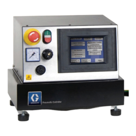
PG-4 PG-2 PG-8 MACHINE I/O PG-1 SPOOL VALVE CYLINDER LOAD DISP . 1: Micrometer PD44 Control Box Key: Emergency Stop Control Power Switch Touch Panel Alarm Speaker Power Input Start Options Connection Custom I/O A Tank Level Controls Connection B Tank Level Controls Connection... -
Page 9: Pd44 Dispense Valve
Grounding Grounding PD44 Dispense Valve See the PD44 Dispense Valve Operation-Parts manual for detailed dispense valve component identification and instructions. See Related Manuals on page 2. The equipment must be grounded to reduce the risk of static sparking and electric shock. Electric or static sparking can cause fumes to ignite or explode. -
Page 10: Setup
Setup Setup 1. Connect the air supply to the main air inlet (K) on 3. Connect the Dispense Valve I/O and Start Options the control box. Air supply must include a logic cables. If level controls are installed, connect shut-off/bleed valve that bleeds pressure past the the Level Controls logic cables. -
Page 11: Startup
Startup Startup Dispensing Operation NOTE: See HMI Operation starting on page 12 for NOTE: See HMI Operation starting on page 12 for detailed HMI instructions. detailed HMI instructions. The foot switch, the Start button, and the optional 1. Press the Control Power On button. Customer Start Signal can be used to initiate shots. -
Page 12: Hmi Operation
Screen Navigation Diagram Main Screen Status Purge Timer Level 1 Control Level 2 Control PD44 Control . 6: Screen Navigation Diagram Main Screen . 7: Main Screen Screen Access Buttons All buttons on the main screen open a new specified screen. -
Page 13: Posidot Control Screen
HMI Operation Posidot Control Screen NOTE: A”1” indicates the mode is ON. A “0” indicates the mode is OFF. . 8: Posidot Control Screen 313877J... - Page 14 Cycle Counter On/Off: This enables (On) or disables (Off) the cycle counter. When the Cycle Counter is enabled and the PD44 is in Shot Mode, the PD44 takes the preset number of cycles when the start device is pressed. The lower left field shows the preset number of cycles the PD44 will take (in this case, seven cycles.
-
Page 15: Timer/Counter Control Screen
HMI Operation Timer/Counter Control Screen NOTE: A”1” indicates the mode is ON. A “0” indicates the mode is OFF. . 9: Timer/Counter Control Screen Calculating the Purge Timer Setting If the shot size is larger than the mixer volume, set the timer for one-half the gel time of the material. - Page 16 Alarm Timer: When the Purge Timer times out, it will sound an audible alarm before the PD44 purges. This is to warn the operator the PD44 is about to cycle so the PD44 can be moved over a waste container or a regular dispense shot can be taken. The blue field is where the operator enters the Alarm Timer preset value in seconds.
-
Page 17: Status Screen
HMI Operation Status Screen NOTE: A”1” indicates the mode is ON. A “0” indicates the mode is OFF. . 10: Status Screen 313877J... - Page 18 PX-CSV/PX-OSV: Displays which spool valve sensor on the PD44 is active (“1” is active, “0” is inactive). When the PD44 is not dispensing, the spool valve is in Reload position. When the PD44 is dispensing it is in the Dispense position.
-
Page 19: Level 1 Control Screen
HMI Operation Level 1 Control Screen NOTE: A”1” indicates the mode is ON. A “0” indicates the mode is OFF. . 11: Level 1 Control Screen 313877J... - Page 20 HMI Operation Icon Description A and B Tank Status: Shows the status of the tanks. See the chart below for the messages and descriptions. Start Fill A or B Button: Starts filling the A (or B) tank by turning on a solenoid for a transfer pump (if purchased).
-
Page 21: Level 2 Control Screen
HMI Operation Level 2 Control Screen NOTE: A”1” indicates the mode is ON. A “0” indicates the mode is OFF. . 12: Level 2 Control Screen 313877J... - Page 22 Shutdown Timer: This is the amount of time in seconds between when a low level sensor in either the A or B tank is activated and when dispensing from the PD44 is disabled. This insures air is not pumped through the PD44. The preset value is changed in the middle field and the actual value of the timer is read in the bottom field.
-
Page 23: Pressure Relief Procedure
3. Perform dispense valve pressure relief procedure. See Related Manuals on page 2. Shutdown 1. Navigate to the PD44 Control screen. 2. Press the Retract button. 3. Press the Extend button. 4. Press the Control Power Switch (B). Ensure every- thing is off. -
Page 24: Recycling And Disposal
Recycling and Disposal Recycling and Disposal Maintenance See the appropriate manuals for dispense valve and End of Product Life feed system maintenance schedules and procedures. See Related Manuals on page 2 At the end of a product’s useful life, recycle it in a responsible manner. -
Page 25: Troubleshooting
Troubleshooting Troubleshooting Follow Pressure Relief Procedure, page 23, before checking or repairing the control box. Problem Cause Solution Dispense valve stalling and no Blocked mixer Check mixer for cured material, material being dispensed despite replace mixer as required adequate input pressure. Flow control valve closed Open Dispense valve not discharging... -
Page 26: Customer Inputs/Outputs
Customer Inputs/Outputs Customer Inputs/Outputs Name Description Ready to Dispense Signal (Output) In Shot Mode, changes state when pump is retracted and LS-EXT is tripped. Cycle-Complete (Output) In Shot Mode, changes state for one second after the retract switch is tripped. Customer Start (Input) In any mode, operates in parallel to the footswitch. -
Page 27: Schematics
Schematics Schematics Electrical Schematics . 14 313877J... - Page 28 Schematics . 15 313877J...
- Page 29 Schematics . 16 313877J...
-
Page 30: Pneumatic Schematic
Schematics Pneumatic Schematic . 17 313877J... -
Page 31: Parts
Parts Parts Electrical Enclosure Electrical Enclosure Ref. Part Description Qty. 81/1053-2/11 FUSE, 5mm x 20mm, 2A, time delay F0300011 RELAY, master control 26D026 CONTROL, PLC, with program 24J189 POWER SUPPLY, 24VDC, 1.75A, 120/240V 26D027 DISPLAY, HMI, color, with program 81/0562-24/11 RELAY, customer signal 15W776 LABEL, warning, electrical 313877J... -
Page 32: Lower Pneumatic Enclosure
Parts Lower Pneumatic Enclosure Lower Pneumatic Enclosure Ref. Part Description Qty. 02/2891-7/50 LOWER BASE, pneumatic components, PD44 636 16M434 VALVE, solenoid, extend/retract solenoid 637 83/0397-24D/11 VALVE, solenoid, spool valve 313877J... -
Page 33: Technical Specifications
Electrical Requirements 120-240V, 50-60 Hz, 0.6 amp @ 120V, 0.3 amp @240V 5 x 20 mm, 2A, time delay Fuses Required (Graco part 81/1053-2/11, Qty = 1) Maximum Amperage 2 amps Dimensions (H x L x W) 13 in. x 12 in. x 15 in. -
Page 34: Graco Standard Warranty
With the exception of any special, extended, or limited warranty published by Graco, Graco will, for a period of twelve months from the date of sale, repair or replace any part of the equipment determined by Graco to be defective.