Advertisement
Quick Links
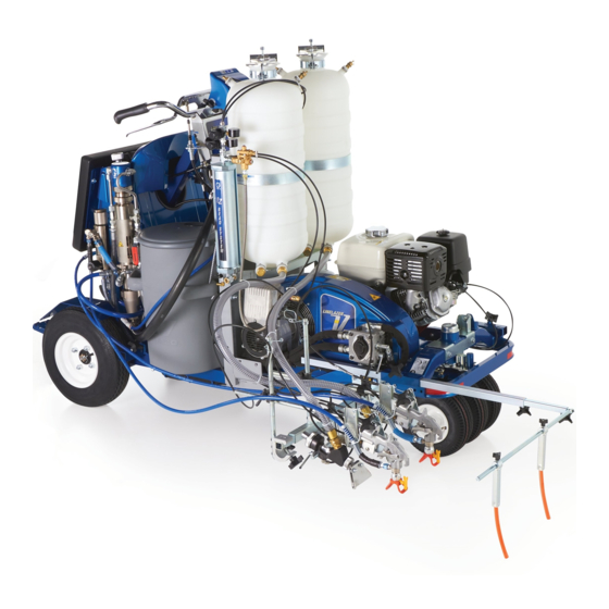
Installation - Operation - Parts
Complete Pressurized Bead System for
LineLazer 200
Models:
16R955 1-Gun LL200
16R962 1-Gun LL250
16R960 2-Gun LL200
16R961 2-Gun LL250
80 psi (.55 MPa, 5.5 bar) Maximum Working Pressure
9
Important Safety Instructions
Read all warnings and instructions in the striper manual.
Be familiar with the controls and the proper usage of the equipment.
Save these instructions.
HS/DC/MMA and
- For professional use only -
HS/MMA
HS/DC/MMA
LineLazer 250
Related Manual
Bead Gun Kit
LLIV 200HS Repair
LLV 200HS/DC Repair and Parts 3A3390
LLV 200MMA Operation, Repair,
and Parts
250DC Repair
332230N
SPS
EN
332226
311021
3A6466
334053
Advertisement

Related Manuals for Graco 16R955


Summary of Contents for Graco 16R955
- Page 1 Complete Pressurized Bead System for 332230N LineLazer 200 LineLazer 250 HS/DC/MMA and - For professional use only - Models: 16R955 1-Gun LL200 HS/MMA 16R962 1-Gun LL250 16R960 2-Gun LL200 HS/DC/MMA 16R961 2-Gun LL250 Related Manual 80 psi (.55 MPa, 5.5 bar) Maximum Working Pressure...
- Page 2 Warnings Warnings The following warnings are for the setup, use, grounding, maintenance, and repair of this equipment. The exclama- tion point symbol alerts you to a general warning and the hazard symbols refer to procedure-specific risks. When these symbols appear in the body of this manual or on warning labels, refer back to these Warnings. Product-specific hazard symbols and warnings not covered in this section may appear throughout the body of this manual where applicable.
- Page 3 Warnings WARNING INJECTION HAZARD High-pressure fluid from gun, hose leaks, or ruptured components will pierce skin. This may look like just a cut, but it is a serious injury that can result in amputation. Get immediate surgical treatment. • Do not spray without tip guard and trigger guard installed. •...
-
Page 4: Tools Needed
Tools Needed: CE Safety Checklist (To be completed during non-factory installation) Covers and shrouds for moving parts are in place (see guard installation section). Fasteners, belts, covers, grills, and compressor are tight-mounted securely. Read and understand all warnings and instructions in this manual and the striper manual. Tools Needed: •... - Page 5 Operation for LL200 and LL250 Operation for LL200 and LL250 Component Identification Ref. Description Ref. Description Pressure Relief Valve Funnel Bead Tank Gauge Wing Nut Pressure Regulator Valve Compressor Bypass Switch Air Tank Gauge Regulator Unloader Safety Relief Valve 332230N...
-
Page 6: Pressure Relief Procedure
Pressure Relief Procedure Pressure Relief Procedure 3. Loosen wing nut (2) until it reaches end of threads. Follow the Pressure Relief Procedure whenever If any remaining pressure is in bead tank, it will be you see this symbol. released through seal while wing nut secures lid to hopper. - Page 7 200HC/DC/MMA Pressurized Bead System Kit 25R268 200HC/DC/MMA Pressurized Bead System Kit 25R268 Assemble Compressor Mounting 3. Assemble hopper basket (XX) and base with hard- ware as shown below. Use 9/16 in. wrench to snug and Drive Components screws. Loosen all six screws 1/4 turn. NOTE: Glass bead system and paint guns can be mounted on either side of sprayer.
- Page 8 200HC/DC/MMA Pressurized Bead System Kit 25R268 Complete Frame Assembly 2. Install plastic end caps (ZZ) into frame. Use rubber mallet to pound end caps into place. NOTE: If desired, rotate recoil 90° counter-clockwise. ti21500a 1. Use 9/16 wrench to tighten bottom screws (MM) to ti20884a hardware shown.
- Page 9 LL200 Compressor Installation LL200 Compressor Installation Tools Needed: 2.5 mm Allen wrench, 4.0 mm Allen wrench, 5. With a 9/16 in. wrench, mount air tank (3) to bracket 1/4 in. Allen wrench, 7/16 in. wrench, 9/16 in. wrench, 11/16 in. with screws (21).
- Page 10 LL200 Compressor Installation 7. Remove hopper. Locate belt shroud. Loosen knob 12. Torque pulley set screws to 58-62 in-lb (6.6-7 N•m). (AA) and rotate shroud (BB). 13. Install belt on pulley. See Ground Drive Belt Replacement in your striper repair manual for additional instructions and belt tension recommendations.
- Page 11 LL200 Compressor Installation 15. Use existing screws to install new fan grill with 16. Using screws (20), install compressor bracket (4) opening (FF) onto shroud (BB). Do not over-tighten with three tabs towards striper. Center shaft coupler screws. Make sure fan grill protrudes out; not into both vertically and horizontally in slot.
- Page 12 LL200 Compressor Installation 18. Slowly pull the starter rope to rotate shaft. With the 19. Slide compressor (1) onto the shaft coupler (5) until keyway of the shaft coupler (5) facing up, place the the face of the compressor is flush with compressor shaft key (2) into the keyway.
- Page 13 LL200 Compressor Installation 20. Use two carriage bolts (9), two washers (10), and 21. Slowly pull the starter rope to rotate until the two two nuts (17) in opposing holes (180 degrees apart) M8x10 set screws appear in the set screw access. to tighten the compressor to the mounting bracket Torque the set screws to 150-160 in-lb (16.9-18 (4).
- Page 14 LL200 Compressor Installation 23. With the compressor secured to the coupler shaft, 24. Install compressor guard using three screws (14), slightly loosen the four mounting screws (20). Install lock washers (15), and flat washers (16). Torque to all four carriage bolts (9), washers (10), and lock 130-150 in-lb (14.7-16.9 N•m).
- Page 15 LL200 Compressor Installation 26. Remove plug from compressor case. Install oil 28. Before operation, ensure oil is visible on threads of breather (1b). fill port. If not full, fill with included oil until visible on threads. NOTICE Failure to properly fill compressor with oil can result in failure and/or severe or catastrophic damage to the compressor.
- Page 16 LL200 Compressor Installation Bead Tank Mounting 3. Install 36 in. nylon air line (dd) from top of regulator to swivel fitting on top of bead hopper. Cut air line to 1. Place bead tank on supporting base with outlet desired length. Push air line into fitting until end fittings facing compressor.
- Page 17 LL250 Pressurized Bead System Kit 25R270 LL250 Pressurized Bead System Kit 25R270 Assemble Compressor Mounting 4. Loosely install two screws (M) and two locknuts (N) through bottom of frame mount. Use 9/16 in. wrench and Drive Components to fully tighten. 1.
- Page 18 LL250 Pressurized Bead System Kit 25R270 9. Assemble hopper bracket (X) and base (Y) with hardware provided. Install carriage bolts with the heads facing the paint tanks. Use 9/16 in. wrench to tighten bolts. Inches Centimeter ti20502a 8. Use 9/16 wrench to tighten bottom screws (M) to hardware shown.
- Page 19 LL250 Compressor Installation LL250 Compressor Installation Tools Needed: 2.5 mm Allen wrench, 4.0 mm Allen wrench, 5. Using a 9/16 in. wrench and screws (19), mount the 1/4 in. Allen wrench, 7/16 in. wrench, 9/16 in. wrench, 11/16 in. air tank to the new air tank bracket (2). wrench, T-20 Torx bit, rubber mallet, Phillips screwdriver.
- Page 20 LL250 Compressor Installation 7. Locate belt shroud. Loosen knob (A) and lift shroud NOTE: Prior to step 14, securing nuts to back of pulley (B). with piece of duct tape will assist with installation. 14. With belt shroud down, install shaft coupler (5) onto pulley (DD) with two shoulder screws (18) and serrated nuts (19).
- Page 21 LL250 Compressor Installation 15. Use existing screws to install new fan grill with 16. Remove two existing bolts and washers from striper opening (FF) onto shroud (B). Do not over-tighten frame. Install compressor bracket (3) with three tabs screws. Make sure fan grill protrudes out; not into towards striper using existing washers and bolts.
- Page 22 LL250 Compressor Installation 17. Place a drop of medium strength thread locker (23) on the threads of each set screw. Using a 2.5 mm NOTICE and a 4.0 mm Allen wrench, screw the set screws Performing steps 19 through 23 out of order, or into the shaft coupler (1a) far enough so that the incorrectly, may cause excessive side loading on the coupler can slide onto the shaft in the compressor...
- Page 23 LL250 Compressor Installation 20. Use two carriage bolts (8), two washers (9), and two 21. Using a long screw driver, slowly rotate the fan nuts (16) in opposing holes (180 degrees apart) to pulley until the two M8x10 set screws appear in the tighten the compressor to the mounting bracket (4).
- Page 24 LL250 Compressor Installation 23. Now that compressor is secured to the coupler 25. Apply thread sealer to threads of tee fitting (6). shaft, slightly loosen the two mounting screws Install tee fitting with safety valve (7) into between the frame and bracket. Install all four compressor output.
- Page 25 LL250 Compressor Installation 26. Remove plug from compressor case. Install oil 27. Before operation, ensure oil is visible on threads of breather (1b). fill port. If not full, fill with included oil until visible on threads. NOTICE Failure to properly fill compressor with oil can result in failure and/or severe or catastrophic damage to the compressor.
- Page 26 LL250 Compressor Installation Bead Tank Mounting 3. Place clamping band around tank and secure with mounting hardware shown below. Tighten until 1. When only one bead tank is being installed, it there is no movement between clamp and bead should be placed on the side of the frame furthest tank.
-
Page 27: Operation
Operation Operation Charging Air Tank Setting Bead Hopper Pressure 1. Start engine and engage clutch. Compressor is now The pressure regulator valve (5) controls pressure sent engaged. from the air tank to the bead tank. The regulator is set to 0 pressure from the factory. 2. - Page 28 Operation Bead Timing With Gun 1. Use air flow restrictor valves to help time the open- ing and closing of the bead guns to best match the start and stop of paint lines. 2. Valve (X) is exhausting air and will control the timing end of the bead application.
- Page 29 Determining Bead Application Pressure Determining Bead Application Pressure The table below lists bead delivery rates for 4 inch 2. Identify what the required bead delivery rate is in job (10 cm) lines with standard size highway beads. specifications. 3. Under bead gun nozzle size, find nearest value •...
- Page 30 Determining Bead Application Pressure Filling Bead Hopper 1. Move compressor bypass switch (9) to horizontal position to disengage compressor or turn engine off. ti21077a 4. Place funnel (1) into opening. Pour beads into hop- ti21074a per. Beads should not be filled to a height higher than shown in figure below.
- Page 31 Determining Bead Application Pressure 0 to 8 in. Line Setup 2 Tank 1 Gun Setup For wider lines it may be necessary to mount bead gun Connect “Y” fitting as shown below to allow two tanks to as shown below. flow into one gun.
- Page 32 Determining Bead Application Pressure Double Drop Setup Use a “Y” fitting to create a dual bead gun setup for double drop beads. Splice exit hose on bottom of air switch and branch into both guns. ti20564a 332230N...
- Page 33 Notes Notes 332230N...
- Page 34 Parts - Model 25R268 Parts - Model 25R268 332230N...
- Page 35 Parts - Model 25R268 Parts List - 25R268 Ref. Part Description Qty. Ref. Part Description Qty. 111194 SCREW, cap flange hd 25R108 COMPRESSOR, PBS 115087 PLUG, tubing 19B286 KIT, collar, shaft 121488 SCREW, hex hd, flanged 25P605 KEY, square, 3/16 x 1.34 16T593 BRACKET, bead tank, LL200, 25P599 BRACKET, air tank painted...
- Page 36 Parts - Model 25R270 Parts - Model 25R270 332230N...
- Page 37 Parts - Model 25R270 Parts List - Model 25R270 Ref. Part Description Qty. Ref. Part Description Qty. 16T594 BRACKET, bead hopper, LL250, 25R108 COMPRESSOR, PBS painted 19B286 KIT, collar, shaft 111194 SCREW, cap flange hd 25P603 BRACKET, air tank LL250 16U273 HOSE, pneumatic 25P601 BRACKET, compressor 250 115087 PLUG, tubing...
-
Page 38: Graco Standard Warranty
With the exception of any special, extended, or limited warranty published by Graco, Graco will, for a period of twelve months from the date of sale, repair or replace any part of the equipment determined by Graco to be defective. -
Page 39: Graco Information
Graco Standard Warranty Graco Information For the latest information about Graco products, visit www.graco.com. For patent information, see www.graco.com/patents. TO PLACE AN ORDER, contact your Graco distributor or call 1-800-690-2894 to identify the nearest distributor. 332230N... - Page 40 This manual contains English. MM 332230 Graco Headquarters: Minneapolis International Offices: Belgium, China, Japan, Korea GRACO INC. AND SUBSIDIARIES • P.O. BOX 1441 • MINNEAPOLIS MN 55440-1441 • USA Copyright 2013, Graco Inc. All Graco manufacturing locations are registered to ISO 9001. www.graco.com...