Table of Contents
Advertisement
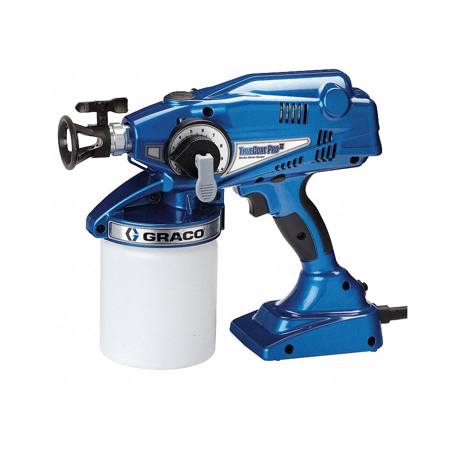
Operation - Repair - Parts
Electric Hand-Held Paint Sprayers
- For portable spray applications of architectural paints and coatings only -
- Not approved for use in explosive atmosphere locations -
IMPORTANT SAFETY INSTRUCTIONS
Read all warnings and instructions in this
manual. Save these instructions.
All Models:
Maximum Working Pressure 2000 psi (14 MPa, 138 bar)
Model
Voltage
16N658
120V
16N659
120V
16N673
Use only water-based or oil-based (mineral spirit-type) materials with flash point greater than 100° F
(38° C). Do not use materials which state "FLAMMABLE" on the packaging. For more information about
your material, request MSDS from distributor or retailer.
Use oil-based materials outdoors or in a well-ventilated indoor area with a flow of fresh air.
Description
Fixed Pressure
Adjustable Pressure
WARNING
WARNING
WARNING
WARNING
Adjustable Pressure
Fixed Pressure
ti18910a
3A2587B
EN
Adjustable Pressure
Advertisement
Table of Contents
Troubleshooting

Related Manuals for Graco 16N658


Summary of Contents for Graco 16N658
- Page 1 Read all warnings and instructions in this manual. Save these instructions. All Models: Adjustable Pressure Maximum Working Pressure 2000 psi (14 MPa, 138 bar) Model Voltage Description 16N658 120V Fixed Pressure 16N659 120V Adjustable Pressure 16N673 Fixed Pressure Adjustable Pressure...
-
Page 2: Table Of Contents
Selecting Tip Hole Size ..... . . 12 Graco Standard Warranty ......32 Choosing Pressure Control Knob Setting . -
Page 3: Warnings
Warnings Warnings The following warnings are for the setup, use, maintenance, and repair of this equipment. The exclamation point sym- bol alerts you to a general warning and the hazard symbols refer to procedure-specific risks. When these symbols appear in the body of this manual or on warning labels, refer back to these Warnings. Product-specific hazard sym- bols and warnings not covered in this section may appear throughout the body of this manual where applicable. - Page 4 Warnings WARNING WARNING WARNING WARNING FIRE AND EXPLOSION HAZARD Flammable fumes, such as solvent and paint fumes, in work area can ignite or explode. To help prevent fire and explosion: • Sprayer generates sparks. Do not spray or flush with flammable liquids. •...
- Page 5 Warnings WARNING WARNING WARNING WARNING EQUIPMENT MISUSE HAZARD Misuse can cause death or serious injury. • Always wear appropriate gloves, eye protection, and a respirator or mask when painting. • Do not operate or spray near children. Keep children away from equipment at all times. •...
-
Page 6: Component Identification
Component Identification Component Identification ti18911a Prime/Spray Valve Spray Tip/Guard Assembly Sprayer Case Spray Tip Filter (Reverse Threaded) Circuit Reset Button Air Vent Valve Power Cord Flexible Suction Tube Sprayer Trigger Pump Armor Storage/Startup Tool Sprayer Trigger Lock Material Cup Cover and Seal Outlet Valve Fitting Access Pressure Adjustment Knob (Not available on all units) -
Page 7: Using Electrical Cords
Using Electrical Cords Using Electrical Cords Grounding and Electrical Extension Cord Requirements Requirements Only use an extension cord with an undamaged 3-prong plug for 120 V. Sprayer must be grounded. Grounding reduces the risk When operating sprayer outdoors, use an extension of static and electric shock by providing an escape wire cord suitable for outdoor use. -
Page 8: Common Procedures
Common Procedures Common Procedures Trigger Lock Follow the Pressure Relief Procedure whenever you see this symbol. Pressure Relief Procedure Always engage the trigger lock when you stop spraying to prevent the sprayer from being triggered accidentally by hand, or if dropped or bumped. Do not operate or spray near children. -
Page 9: Reversible Spray Tip
Common Procedures Reversible Spray Tip • Thin materials sprayed at high pressure settings may cause the sprayer to enter an operational mode designed to protect it from overheating. This mode is noticeable by the sprayer sounding like it is slow- ing down and will result in a poor spray pattern. -
Page 10: Sprayer Setup
Sprayer Setup Sprayer Setup 3. Put prime/spray valve DOWN to spray position. Use only water-based or oil-based (mineral ti16701a spirit-type) materials with flash point greater than ti15425a 100° F (38° C). Do not use materials which state “FLAMMABLE” on the packaging. For more information 4. -
Page 11: Starting A New Job (Or Refilling The Material Cup)
Starting a New Job (or Refilling the Material Cup) Starting a New Job If sprayer fails to prime, try one of the steps below: (or Refilling the Material Cup) 1. Use the Pump Armor storage/startup tool to clean Engage trigger lock and put prime/spray valve UP to the inlet valve fitting. -
Page 12: Choosing The Correct Tip
Choosing the Correct Tip Choosing the Correct Tip Understanding Tip Number Selecting Tip Hole Size The last three digits of tip number (i.e.: XXX515) con- • Tips come in a variety of hole sizes for spraying a tains information about hole size and fan width on sur- range of fluids. -
Page 13: Install Spray Tip/Guard Assembly (If Not Installed)
Install Spray Tip/Guard Assembly (if not installed) Getting Started with Basic Install Spray Tip/Guard Techniques Assembly (if not installed) Use a piece of scrap cardboard to practice these basic spraying techniques before you begin spraying the surface. • Hold sprayer 10 in. (25 cm) from surface and aim straight at surface. -
Page 14: Aiming Sprayer
Unclogging Spray Tip/Guard Assembly Aiming Sprayer Aim sprayer at waste area, disengage trigger lock, and put prime/spray valve DOWN to spray position. Pull Aim spray tip of sprayer at bottom edge of previous stroke, trigger to clear clog. overlapping each stroke by half. ti16701a ti18913a ti18917a... -
Page 15: Shutdown And Cleaning
Do not store solvents ti19034a other than mineral spirits in sprayer. Always flush with Graco Pump Armor prior to storage. NOTICE When removing flexible suction tube from sprayer, make Flushing Sprayer sure to pull directly on top fitting of flexible suction tube. - Page 16 Shutdown and Cleaning Reconnect material cup and shake sprayer to move 13. Engage trigger lock and put prime/spray valve UP to clean water around and clean all areas inside of cup. release pressure. ti16700a ti18912a ti14994a NOTE: Air vent holes or the air vent valve (as your ti18920a model is equipped) allow air to flow into the material Disconnect trigger lock and trigger sprayer for approxi-...
-
Page 17: Cleaning Sprayer Exterior
Storage Cleaning Sprayer Exterior 3. Hold sprayer upside-down over a waste container. • Wipe paint off outside of sprayer using a soft cloth moistened with water or flushing fluid. Do NOT submerge the sprayer. Do NOT use solvents with a flash point greater than 100°... -
Page 18: Replacement Parts
Replacement Parts Replacement Parts Models 16N658, 16N659, 16N673 ti19438a 3A2587B... -
Page 19: Parts List - Models 16N658, 16N659, 16N673
Replacement Parts Parts List - Models 16N658, 16N659, 16N673 If you have this model sprayer Order Part Ref. Description (model number is the same as the part number, Number: which is below the handle) All models 243103 Pump Armor (32 oz) - Page 20 Replacement Parts Parts List - Models 16N658, 16N659, 16N673 (Continued) If you have this model sprayer Order Part Ref. Description (model number is the same as the part number, Number: which is below the handle) All models 16M864 Reciprocator Assembly Kit (includes parts 20, 28, 44, 55)
-
Page 21: Inlet Valve Fitting Removal/Service
Inlet Valve Fitting Removal/Service Inlet Valve Fitting Clean as much excess material from inlet cavity as possible. Make sure you also clean spring (a), inlet Removal/Service valve (b), o-ring (c), and top of inlet valve fitting (d). Use a thin wire less than 1/16 in. (such as a paper clip) to check that the outlet valve fitting moves freely. -
Page 22: Outlet Valve Fitting Repair
Outlet Valve Fitting Repair Outlet Valve Fitting Repair 4. Use tool (supplied) to loosen and remove outlet valve fitting. Make sure old o-ring, seat, outlet valve, and spring are out of pump outlet cavity. This equipment stays pressurized until pressure is manually relieved. -
Page 23: General Service
General Service Position pressure control knob in fully clockwise position and press firmly onto retainer. See manual 3A1884 (available at www.graco.com) for complete instructions on properly servicing your sprayer. If you have opened the sprayer clamshell and do not have... -
Page 24: Troubleshooting
Troubleshooting Troubleshooting Check everything in this Troubleshooting Table before you bring the sprayer to an authorized service center. This equipment stays pressurized until pressure is manually relieved. To help prevent serious injury from pressurized fluid, such as skin injection, splashing fluid and moving parts, follow the Pressure Relief Procedure when you stop spraying and before cleaning, checking, or servicing the equipment. - Page 25 Troubleshooting Problem Cause Solution Sprayer sprays with poor results Spray tip is partially clogged See Unclogging Spray Tip/Guard Assembly, page 14. Spray tip is not in correct position Rotate spray tip to SPRAY position. Incorrect spray tip for application of See Reversible Spray Tip Selection Chart, material.
- Page 26 Troubleshooting Problem Cause Solution Spray pattern is too narrow: Sprayer is too close to target surface. Move sprayer away from surface 10 in. (25 cm) Incorrect spray tip for application of material. See Reversible Spray Tip Selection Chart, page 12. Spray tip is worn or damaged.
-
Page 27: Troubleshooting Leaks
Troubleshooting Troubleshooting Leaks Point C Points A Points D Point B ti19436a Problem Cause Solution Sprayer is leaking fluid at Points A Spray/tip guard assembly is loose. Tighten spray/tip guard assembly. O-ring inside needle assembly is Replace o-ring (108195). worn out. Sprayer is leaking fluid at Point B O-ring on rear of needle assembly is Replace o-ring (108195). -
Page 28: Technical Data
Technical Data Technical Data Hand-Held Sprayer (Models: 16N658, 16N659) U.S. Metric Adjustable Pressure Range 1000 - 2000 psi 7 - 14 MPa, 69 - 138 bar Fixed Pressure 1300 psi 9.9 MPa, 89.6 bar Maximum Amperage 4 Amps 4 Amps... -
Page 29: Preferred Material Settings Log
Preferred Material Settings Log Preferred Material Settings Log Item Material Spray Pressure Setting Date Sprayed Sprayed (Mark Dial) 03/24/2011 Crown molding Water-based XWD 515 3A2587B... -
Page 30: Notes
Notes Notes 3A2587B... -
Page 31: Notes
Notes Notes 3A2587B... -
Page 32: Graco Standard Warranty
With the exception of any special, extended, or limited warranty published by Graco, Graco will, for a period of twelve months from the date of sale, repair or replace any part of the equipment determined by Graco to be defective.