
Related Manuals for Endress+Hauser IO-Link Liquipoint FTW23


Summary of Contents for Endress+Hauser IO-Link Liquipoint FTW23
- Page 1 Products Solutions Services BA01792F/00/EN/01.17 71378479 Operating Instructions Liquipoint FTW23 IO-Link Capacitance point level measurement...
- Page 2 Liquipoint FTW23 IO-Link Order code: XXXXX-XXXXXX Ser. no.: XXXXXXXXXXXX Ext. ord. cd.: XXX.XXXX.XX Serial number www.endress.com/deviceviewer Endress+Hauser Operations App A0023555 Endress+Hauser...
-
Page 3: Table Of Contents
Function of LEDs ..... . 21 Function testing of switch output ..22 Endress+Hauser... -
Page 4: Document Information
Symbol Meaning Preferred Procedures, processes or actions that are preferred. Permitted Procedures, processes or actions that are permitted. Forbidden Procedures, processes or actions that are forbidden. Indicates additional information. Reference to page Series of steps 1. 2. 3. … Endress+Hauser... -
Page 5: Documentation
Additional documentation TI00426F/00/EN Weld-in adapter, process adapter and flanges (overview) SD01622Z/00/YY Weld-in adapter G 1", G ¾" (installation instructions) BA00361F/00/A6 Weld-in adapter M24x1.5 (installation instructions) Registered trademarks is a registered trademark of the IO-Link company group. Endress+Hauser... -
Page 6: Basic Safety Instructions
It meets general safety standards and legal requirements. It also complies with the EC directives listed in the device-specific EC Declaration of Conformity. Endress+Hauser confirms this by affixing the CE mark to the device. Endress+Hauser... -
Page 7: Product Description
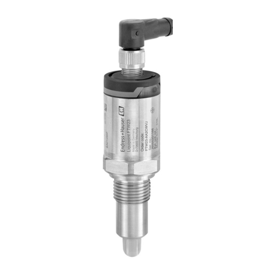
Product design A0024689 1 Product design of Liquipoint FTW23 M12 connector Plastic housing cover IP65/67 Metal housing cover IP66/68/69 Housing Process connection (G ½", G ¾", G 1", M24x1.5) Sensor Endress+Hauser... -
Page 8: Incoming Acceptance And Product
The serial number on the nameplate can also be used to obtain an overview of the technical documentation supplied with the device in W@MDevice Viewer (www.endress.com/deviceviewer) 4.2.1 Manufacturer address Endress+Hauser GmbH+Co. KG Hauptstraße 1 79689 Maulburg, Germany Address of the manufacturing plant: See nameplate. Endress+Hauser... -
Page 9: Storage And Transport
→ 37. Storage and transport 4.3.1 Storage conditions • Permitted storage temperature: –40 to +85 °C (–40 to +185 °F) • Use original packaging. 4.3.2 Transportation to measuring point Transport the device to the measuring point in the original packaging. Endress+Hauser... -
Page 10: Installation
Mounting the measuring device 5.2.1 Required tools Open-ended wrench or socket wrench 32 AF – When screwing in, turn by the hex bolt only. – Torque: 15 to 30 Nm (11 to 22 lbf ft) Endress+Hauser... -
Page 11: Post-Installation Check
Take account of metallic or non-metallic vessels or pipes in accordance with EMC guidelines, see Technical Information TI01202F. Post-installation check Is the device undamaged (visual inspection)? Is the device adequately protected from wet conditions and direct sunlight? Is the device properly secured? Endress+Hauser... -
Page 12: Electrical Connection
DC-PNP (Q2) Supply voltage - C/Q (IO-Link communication or SIO mode) Electrical connection Operating mode (SIO mode with factory setting) M12 connector 0.5A 0.5A L– L– L+ Symbols Description Yellow LED (ye) lit Yellow LED (ye) not lit external load Endress+Hauser... -
Page 13: Post-Connection Check
Are the cable glands mounted and firmly tightened? Does the supply voltage match the specifications on the nameplate? If supply voltage is present, is the green LED lit? With IO-Link communication: is the green LED flashing? Endress+Hauser... -
Page 14: Operation Options
– Article number – Product type 7.1.2 Structure of the operating menu The menu structure has been implemented according to VDMA 24574-1 and complemented by Endress+Hauser-specific menu items. For an overview of the operating menu, see → 27 Endress+Hauser... -
Page 15: System Integration
Service Data Unit) Device data are always exchanged acyclically and at the request of the IO-Link master. Using the device data, the following parameter values or device statuses can be read out: 8.2.1 Endress+Hauser-specific device data Designation ISDU ISDU Size... - Page 16 0 to 2^32 µC-Temperature 0x005B Int8 °C: 0 / 1 -128...127 °F: 32 / 1.8 K: 273.15 / 1 Unit changeover 0x0050 UInt8 °C 0 ~ °C 0 / 0 0...2 (UNI) - µC- 1 ~ °F Temperature 2 ~ K Endress+Hauser...
-
Page 17: Overview Of Diagnostic Events
0x0012 max. 64 String Liquipoint ProductText 0x0014 max. 64 String Capacitance point level switch VendorName 0x0010 max. 64 String Endress+Hauser VendorText 0x0011 max. 64 String People for Process Automation Hardware Revision 0x0016 max. 64 String Application Specific Tag 0x0018 String... -
Page 18: Function Check
3. Enter the measured values for the switch point and switchback point. The set value for the switch point "SP1"/"SP2" must be greater than the switchback point "rP1" /"rP2" → 32. Setting: Switch point value (Coverage), Output 1/2 (SP1/2 or FH1/2) and Switchback point value (Coverage), Output 1/2 (rP1/2 or FL1/2) Endress+Hauser... -
Page 19: Window Function, Media Detection/Differentiation
This calibration is suitable if the measured values of the medium are known. For reliable detection of the medium, the process window must be sufficiently large. 1. Navigate to the Application menu level Setting: Active switchpoints = User Endress+Hauser... -
Page 20: Application Example
Medium detection/Process window 0-signal, output open 1-signal, output closed Coverage of sensor Medium 1, process window 1 Medium 2, process window 2 FNO Closing FNC NC contact FH1 / FH2 Upper value process window FL1 / FL2 Lower value process window Endress+Hauser... -
Page 21: Light Signals (Leds)
The IP69K protection class is defined in accordance with DIN 40050 Part 9. This standard was withdrawn on November 1, 2012 and replaced by DIN EN 60529. As a result, the name of the IP protection class has changed to IP69. Endress+Hauser... -
Page 22: Function Testing Of Switch Output
The device returns automatically to the current switch status. The test magnet is not included in the scope of delivery. It can be ordered as an optional accessory → 37. A0024417 6 Position for test magnet on housing Endress+Hauser... -
Page 23: Diagnostics And Troubleshooting
Repeat function test. for too long Red LED Internal sensor error Replace device. LED display on M12 connector, can be ordered as an accessory Malfunction Possible cause Measure Green LED No power supply Check connector, cable and power supply. not lit Endress+Hauser... -
Page 24: Diagnostic Events
Example A0013959 If two or more diagnostic events are pending simultaneously, only the diagnostic message with the highest priority is shown. The last diagnostic message is displayed - see Last Diagnostic (LST) in the Diagnosis submenu → 29. Endress+Hauser... -
Page 25: Behavior Of The Device In The Event Of A Fault
(switch outputs de-energized). – The fault state is displayed via IO-Link. – The switch output changes to the "open" state. 10.5 Resetting to factory settings (reset) See Reset to factory settings (RES) parameter description→ 36. Endress+Hauser... -
Page 26: Maintenance
The measuring device must be returned if the wrong device has been ordered or delivered. As an ISO-certified company and also due to legal regulations, Endress+Hauser is obliged to follow certain procedures when handling any returned products that have been in contact with medium. -
Page 27: Overview Of The Onsite Display
Maximum µC-Temperature → 36 Reset to factory settings → 36 Device Access Locks.Data Storage Lock → 36 Observation Coverage → 37 Switch State Output 1 → 37 Switch State Output 2 → 37 Endress+Hauser... -
Page 28: Description Of Device Parameters
Displays the ENP version (ENP: electronic name plate) Application Specific Tag Navigation Identification → Application Specific Tag Description Used for unique identification of device in the field. Enter device tag (max. 32 alphanumeric characters). Factory setting As per order specifications Endress+Hauser... -
Page 29: Diagnosis
If the device is disconnected from the power supply during the simulation and power is then resupplied, the simulation mode is not resumed, and instead the device continues operation in the measuring mode. Options • Off • ou2 = high • ou2 = low Endress+Hauser... - Page 30 The sensor must not be covered and must be free of residue. The device compares the current measured values with the measured values from the factory calibration. Options Check: Following the test, one of the following messages is displayed: • Message (0x1814) for sensor check passed • Message C103 (0x1813) for sensor check failed Endress+Hauser...
-
Page 31: Parameter
Calibrate coverage, Output 1/2 (OU1/OU2) Navigation Application → Calibrate coverage, Output 1/2 (OU1/OU2) Description Wet calibration with covered sensor. A switching threshold that suits the process is generated with the measuring signal that is present. Example → 18 ff Endress+Hauser... - Page 32 Hysteresis (difference between the value of the switch point SP1/SP2 and the value of the switchback point rP1/rP2) Coverage of sensor HNO Normally open contact (MIN) HNC Normally closed contact (MAX) SP1 Switch point 1 / SP2: Switch point 2 rP1 Switchback point 1 / rP2: Switchback point 2 Endress+Hauser...
- Page 33 No selection. The user is free to edit the values. Input range 0 to 200 Factory setting 77.5 % switch point (coverage of sensor), output 1 (SP1) 73 % switchback point (coverage of sensor), output 1 (rP1) Switching delay time, Output 1/2 (dS1/dS2) Switchback delay time, Output 1/2 (dR1/dS2) Endress+Hauser...
- Page 34 Last value selected prior to switching off. Options No selection. The user is free to edit the values. Input range 0.3 to 600 Factory setting 0.5 s (Switching delay time dS1/dS2) 1.0 s (Switchback delay time dR1/dR2) Output 1/2 (OU1/OU2) Endress+Hauser...
- Page 35 This parameter is used to select the electronics temperature unit. Once a new electronics temperature unit has been selected, the new unit is calculated and displayed. Switch on value Last unit selected prior to switching off. Options • °C • °F • K Factory setting °C Endress+Hauser...
- Page 36 The following parameters are not reset when a reset is performed: • Minimum µC-Temperature • Maximum µC-Temperature • Last Diagnostic (LST) • Operating hours Note The last error is not reset in a reset. Device Access Locks.Data Storage Lock Navigation System → Device Access Locks.Data Storage Lock Endress+Hauser...
-
Page 37: Observation
• Slotted nut Cu Sn/Ni • Body: PBT ~52.5 (2.07) Wire colors for M12 connector: 1 = BN (brown), 2 = WT (white), 3 = BU (blue), 4 = BK (black) Detailed information on accessories can be found in the technical documentation TI01202F/00/EN. Endress+Hauser... -
Page 38: Index
Operating modes ......12 Output 1/2 (OU1/OU2) ..... . . 34 Endress+Hauser... - Page 40 *71378479* 71378479 www.addresses.endress.com...