Endress+Hauser Solimotion FTR20 Operating Instructions Manual
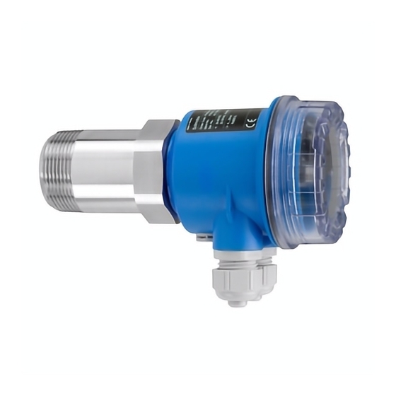
Flow indicator for bulk solids
Hide thumbs
Also See for Solimotion FTR20:
- Operating instructions manual (76 pages) ,
- Technical information (44 pages) ,
- Instructions manual (16 pages)

Related Manuals for Endress+Hauser Solimotion FTR20


Summary of Contents for Endress+Hauser Solimotion FTR20
- Page 1 Products Solutions Services BA01136F/97/EN/07.20 71467968 Operating Instructions Solimotion FTR20 Flow indicator for bulk solids...
- Page 2 Liquiphant FTL4 Solimotion FTR20 Liquiphant FT Order code: XXXXX-XXXXXX Solimotion FTR20 Ser. no.: XXXXXXXXXXXX Ext. ord. cd.: XXX.XXXX.XX Order code: Ext. ord. cd.: Ser.-No.: Order code: XXXXX-XXXXXX Ser. no.: XXXXXXXXXXXX Ext. ord. cd.: XXX.XXXX.XX Serial number Date: www.endress.com/deviceviewer Endress+Hauser Operations App Serial number www.endress.com/deviceviewer...
-
Page 3: Table Of Contents
Resetting to factory defaults (function F) ........................45 Simulation ..................................46 Diagnostics and troubleshooting ������������������������������������������������������������������������������� 47 General troubleshooting ..............................47 Diagnostic information ..............................47 Resetting the device ................................. 47 Maintenance ���������������������������������������������������������������������������������������������������������������� 48 10.1 Maintenance recommendation ............................48 10.2 Endress+Hauser services ..............................48 Endress+Hauser... - Page 4 Spare parts ..................................50 11.3 Return ....................................52 11.4 Disposal ..................................... 52 Accessories ������������������������������������������������������������������������������������������������������������������ 54 Technical specifications ���������������������������������������������������������������������������������������������� 55 Appendix ���������������������������������������������������������������������������������������������������������������������� 56 14.1 Settings of the Solimotion FTR20 ........................... 56 14.2 Overview of the device functions ............................ 57 Index �������������������������������������������������������������������������������������������������������������������������������������� 59 Endress+Hauser...
-
Page 5: About This Document
Solimotion FTR20 About this document About this document 1�1 Document function These operating instructions contain all the information that is required in the various phases of the life cycle of the device: From product identification, incoming acceptance and storage, to installation, connection, operation and commissioning through to troubleshooting, maintenance and disposal. 1�2 Symbols 1�2�1 Safety symbols This warning alerts you to a dangerous situation. Failure to avoid this situation can result in serious or fatal injury. -
Page 6: Documentation
About this document Solimotion FTR20 1�2�5 Device-specific symbols LED on Indicates an illuminated LED LED off Indicates a non-illuminated LED Configuration mode Indicates the function number or value Normal operation Indicates only the signal strength of the bulk solids movement Key (+) Indicates the key for increasing a function value... - Page 7 Solimotion FTR20 About this document 1�3�2 Supplementary device-dependent documentation Depending on the approval, safety instructions (XA) are supplied with the device when it is delivered. These safety instructions are an integral part of the operating instructions. Feature 010 Approval Safety instructions ATEX II 1/2D Ex ta/tb IIIC T102°C Da/Db IP66 XA00524F/97/A3 ATEX II 2D Ex tb IIIC T102°C Db IP66...
-
Page 8: Basic Safety Instructions
Basic safety instructions Solimotion FTR20 Basic safety instructions 2�1 Requirements for personnel The personnel for installation, commissioning, diagnostics and maintenance must meet the following requirements: • T rained, qualified specialists: Must be qualified for this specific role and task • Authorized by the plant operator • Familiar with national regulations • Before starting work: Read and make sure you have understood the instructions in the... -
Page 9: Workplace Safety
Solimotion FTR20 Basic safety instructions 2�3 Workplace safety When working on and with the device: • Wear the required personal protective equipment in accordance with national regulations. 2�4 Operational safety Risk of injury! • The device may only be operated if it is in perfect working order and is free from faults. -
Page 10: Product Description
½ NPT thread, metal (Binder series 713/763) Process connection G 1½ thread R 1½ thread 1½ NPT thread D etails about the available device variants can be viewed in the product configurator on the Endress+Hauser homepage www.endress.com. 3�2 Functional principle The FTR20 transmits a signal that is reflected by the moving bulk solids. In doing so, the device measures the strength of the reflected, frequency-shifted energy (Doppler effect) and uses it to form a display value or output signal. Details about Technical data ... -
Page 11: Incoming Acceptance And Product Identification
Is the order code on the delivery note (1) identical to the order code on the product sticker (2)? Are the goods undamaged? Do the specifications on the nameplate correspond to the order information and the delivery note? I f one of the conditions is not satisfied: Contact your Endress+Hauser sales center 4�2 Product identification You can identify your device in the following ways: • Using the nameplate specifications •... -
Page 12: Nameplate
Incoming acceptance and product identification Solimotion FTR20 4�3 Nameplate Solimotion FTR20 Order code: Ext. ord. cd.: Ser. no.: Date: 2 Example of a nameplate Place of manufacture Order code Extended order code Serial number Degree of protection (IP rating) Ambient temperature range, optional text for approval Operating instructions and safety instructions for the device Date of manufacture: Year-Month CE mark Input and output parameters 4�4 Storage and transportation Please note the following points: • Store in the original packaging to ensure protection from shock. -
Page 13: Installation
Solimotion FTR20 Installation Installation 5�1 Installation requirements The Solimotion FTR20 flow indicator for bulk solids comes with a standard thread (R 1½ as per EN 10226, 1½ NPT as per ANSI/ASME B1.20.1 or G 1½ as per ISO 228-1) as a process connection. This enables easy installation in existing container couplings or nozzles. F or devices intended for use in hazardous areas, please read the information and comply with the instructions in the Ex documentation (XA). For optimal orientation after installation in the process, the electronics housing can be rotated as desired (by 360 °). α α 3 Installation position •... -
Page 14: Installing The Ftr20
Installation Solimotion FTR20 α = 45 ° 4 Installation position for material detection on conveyor belt • Choose a location to install the device where application-specific influences will be minimal. • With vibrating mounting locations it is recommended to use devices with encapsulated electronics (see ordering structure "Accessory mounted"). F or devices intended for use in hazardous areas, please read the information and comply with the instructions in the Ex documentation (XA). 5�2 Installing the FTR20 5�2�1... - Page 15 Solimotion FTR20 Installation Installation procedure: Screw the R 1½ or 1½ NPT self-sealing connecting thread into existing screw-in thread. 55 mm (AF) Align the housing of the electronics. Fix the housing in place. 2 mm 5�2�1�2 Installation with non-self-sealing connection thread (G 1½) 6...
-
Page 16: Post-Installation Check
Installation Solimotion FTR20 5�2�2 Installation with accessories A choice of different process adapters is available from the range of accessories, depending on where you want to install the device and on the process conditions. • For more information on the range of available accessories → 54 • For more information on the various installation options ... -
Page 17: Electrical Connection
Solimotion FTR20 Electrical connection Electrical connection 6�1 Connection requirements Please note the following points before connecting up the device: • T he voltage supply must match the voltage specified on the nameplate. • Switch off the supply voltage before connecting the device. • Connect a potential matching line to the terminal to be used on the FTR20 before connecting the device to the power supply. -
Page 18: Potential Equalization
Electrical connection Solimotion FTR20 The optional enclosed plug connectors must fulfil the following requirements: • Clamping range of the connection cable: - 6 ... 8 mm (M12 plug connector, Binder series 713/763) - 7 ... 10.5 mm (Harting HAN8D plug connector) • Cable cross-sections: max. 0.75 mm or AWG 18 • T he plug connectors are only approved for connecting fixed cables. The operator must provide suitable strain relief. For the electrical connection with connectors there are suitable prefabricated connection cables available as accessory (→ 54). - Page 19 Solimotion FTR20 Electrical connection 6�3�1 Connection of F16 housing (plastic) 7 Device connection F16 housing Connection terminals Internal potential equalization connection External potential equalization connection Cable gland (clamping areas 5 to 10 mm as per EN 50262 or 7 to 10 mm as per UL-514 B) Connection cable M12 connector (Binder series 713/763) Harting connector type HAN8D Procedure of connection with terminals and cable glands: I nsert cable into cable gland, tighten cap nut until the rubber seal is touched all around and then tighten cap nut with by ½ turn. Connect the protective ground.
- Page 20 Electrical connection Solimotion FTR20 6�3�2 Connection of F15 housing (stainless steel) 8 Device connection F15 housing Connection terminals Cable gland (clamping area 7 to 10.5 mm) Connection cable Internal potential equalization connection M12 connector (Binder series 713/763) External potential equalization connection (only for device versions with connector) Harting connector type HAN8D Procedure of connection: I nsert cable into cable gland, tighten the cap nut (torque of up to 10 Nm). Connect the protective ground. Connect the power supply and signal output. Procedure of connection with connectors: Connect the protective ground.
- Page 21 Solimotion FTR20 Electrical connection 6�3�3 Connection of F34 housing (aluminium) 9 Device connection F34 housing Cable gland (clamping area 7 to 10.5 mm) Connection cable M12 connector (Binder type 713/763) Harting connector type HAN8D Internal potential equalization connection Connection terminals External potential equalization connection Procedure of connection: I nsert cable into cable gland, tighten the cap nut (torque of up to 10 Nm). Connect the protective ground. Connect the power supply and signal output. Procedure of connection with connectors: Connect the protective ground.
- Page 22 Electrical connection Solimotion FTR20 6�3�4 Power supply connection 10 Power supply connection (connector 1) Terminal assignment power supply Pin assignment power supply connector 1 (Binder) Pin assignment power supply connector 1 (Harting) Depending on the device version selected, a power supply with the following values can be connected to the FTR20: • 85 to 253 V, 50/60 Hz • 20 to 60 V or 20 to 30 V, 50/60 Hz Electrical connection Power supply Connection terminals Terminal 1 − 2 M12 connector (Binder series 713/763) Connector 1, contact 1 − 2 Harting connector type HAN8D Connector 1, contact 1 − 2 • The polarity of the supply voltage can be set as required.
- Page 23 Solimotion FTR20 Electrical connection 6�3�5 Signal output connection 11 Signal output connection (connector 2) Terminal assignment signal output Pin assignment signal output connector 1 (Binder) Pin assignment signal output connector 1 (Harting) 6�3�5�1 Signal outputs 3 (NO) 4 (CC) 5 (NC) 12 Signal outputs Relay Solid-state relay Current Endress+Hauser...
- Page 24 Electrical connection Solimotion FTR20 6�3�5�2 Relay The following characteristic data apply for the relay signal output (floating switchover contact): • S witching capacity: 250 V / 4 A, 125 V / 0.4 A or 30 V / 4 A • Switching frequency: max. 2 Hz Electrical connection Relay Connection terminals Terminal 3 (NO) Terminal 4 (CC) Terminal 5 (NC) M12 connector (Binder series 713/763) Connector 2 Terminal 2 (NO)
-
Page 25: Post-Connection Check
Solimotion FTR20 Electrical connection 6�4 Post-connection check Are the device and the connecting cable(s) undamaged (visual inspection)? Do the cables used comply with the requirements? Do the mounted cables have adequate strain relief? Are all cable glands or connectors installed, firmly tightened and correctly sealed? Does the supply voltage match the specifications on the nameplate? ... -
Page 26: Operability
Operability Solimotion FTR20 Operability 7�1 Overview The Solimotion FTR20 is configured using a function selection switch (encoding switch) and two operating buttons (adjustment to the sensitivity needed for clear and unambiguous material flow detection). The parameter configuration is stored internally and is retained even after the supply voltage is disconnected. No other operator intervention is necessary during operation. 13 Display and operation elements Display - Signal strength in normal mode - Function number and function value in configuration mode Switch output LED (yellow), relay and solid-state relay Operating button for increase or toggle Operating button for decrease or toggle Function selection switch Ready LED (green) •... -
Page 27: Structure And Function Of The Operating Menu
Example: Function 3 (manual calibration for moving bulk solids) → Y ou can use the two operating buttons to increase or decrease the sensitivity. → → → → T he configured value is stored as soon as the function is switched. The value can be displayed again at any time by selecting the corresponding parameter configuration function and changed if necessary. O nce parameter configuration is complete (i.e. once the flow indicator has been adapted to the bulk solids in question), the encoding switch must be returned to the "0" position. The Solimotion FTR20 is now ready for operation. Endress+Hauser... -
Page 28: Commissioning
• "Post-connection check" checklist → 25 You can write down all selected settings for documentation purposes (table → 56). 8�2 Switching on the device The Solimotion FTR20 will be switched on by an applied power supply. The green LED glows when power supply is applied. 8�3 Configuring the device The Solimotion FTR20 can be calibrated under the following conditions: Calibration in the process for moving bulk solids • A utomatic calibration for moving bulk solids (Function 1, → 29), sufficient for most... - Page 29 Solimotion FTR20 Commissioning 8�3�1 Calibration with movement of bulk solids The automatic calibration with movement of bulk solids (Function 1) is adequate for most applications. If the bulk solids movement after an automatic calibration is not detected as desired, you can adjust the Solimotion to the application manually using an additional manual calibration. Set encoding switch to Position 1 → Display of the function number After 2 seconds: Display of the current signal strength, example: Simultaneously press the keys on the device with maximum solid flow → Automatic calibration is carried out → Display of the signal strength with maximum solid flow...
- Page 30 Commissioning Solimotion FTR20 8.3.2 Calibration with no movement of bulk solids or minimum solid flow The automatic calibration with no movement of bulk solids or minimum solid flow (function 2) is adequate for most applications. If movement is detected anyways after an automatic calibration with no movement of bulk solids (for example, movement in the area surrounding the measuring point), the Solimotion can be manually adapted to the application using an additional manual calibration. Move the encoding switch to position 2 → Display of the function number After 2 seconds: Display of the current signal strength, example: Simultaneously press the keys on the device with no movement of bulk solids or minimum solid flow → Automatic calibration is carried out → Display of the signal strength with no movement of bulk solids or minimum solid flow Move the encoding switch to the initial position 0 → Display of the current signal strength...
- Page 31 • Calibration of the Solimotion outside of the process • Adoption of the calibration parameters with a device replacement at the same measuring point Introduction The Solimotion FTR20 detects the movement of a wide variety of bulk solids. The total detection range (0 to 100 % minimum to maximum possible signal strength) is designed to be correspondingly wide. This way even products with bad reflection properties (small signal strengths), such as rigid polystyrene foam, can be detected.
- Page 32 Commissioning Solimotion FTR20 8�3�3�1 Detection range (function C) 16 Detection range settings Configured detection range (here 3 LEDs) Maximum possible detection range depending on the gain The detection range can be configured depending on the gain (function B) in the range from 1 to a maximum of 10 LEDs (corresponds to the maximum possible detection range). 100 % 17 Detection range depending on gain Illuminated LEDs of the signal strength display Total available detection range Setting in function C The detection range is configured as follows: Move the encoding switch to position C → Display of the function number...
- Page 33 Solimotion FTR20 Commissioning Press the key on the device to increase or decrease the detection range depending on the gain → Display of the changed detection range, example: (detection range decreased by 1 LED) Move the encoding switch to the initial position 0 → Display of the current signal strength • I f the difference between maximum and minimum signal strength in the process is large (fluctuations in the solid flow), a larger detection range should be selected.
- Page 34 Commissioning Solimotion FTR20 Depending on the detection range, it can be configured in the range from 1 to a maximum of 10 LEDs in 20 increments (2 increments correspond to 1 LED). The smaller the detection range selected, the larger the gain selected can be (→ 32). 100 % 19 Gain Illuminated LEDs of the signal strength display Total available detection range Setting in function B The gain is configured as follows: Move the encoding switch to position B → Display of the function number → After 2 seconds: Display of the configured gain, example: Press the key on the device to increase or decrease the gain depending on the detection range (see the following table) → Display of the changed gain, example:...
- Page 35 Solimotion FTR20 Commissioning • I f bulk solids with bad reflection properties (small signal strength) are detected, the detection range should be shifted in the direction of smaller signal strengths (high gain). • I f bulk solids with good reflection properties (large signal strength) are detected, the detection range should be shifted in the direction of larger signal strengths (low gain). • Adjust the detection range and gain until the display of the signal strength has reliably exceeded/undershot the upper and lower switch point (→ 31) (switch output) or the desired output signal has been output (output current). Overview of the dependency between detection range and gain...
- Page 36 Commissioning Solimotion FTR20 8�3�4 Example of bulk solids detection on a conveyor belt The bulk solids for which movement is to be detected are transported via a conveyor belt. Due to process fluctuations, the belt is loaded unevenly. 20 Bulk solids detection on a conveyor belt Default setting of the Solimotion FTR20 (→ 47) Gain (function B) Detection range (function C) Signal strength display in this particular example with the default settings: maximum loading (current output: 15.2 mA)
- Page 37 Solimotion FTR20 Commissioning 8�3�4�1 Example: Calibrate switch output For example, the Solimotion FTR20 with switch output should be calibrated such that the output relay remains closed despite the fluctuating signal strength (if loading of the belt is low (= minimum signal strength), the switch point (LED 5) must remain reliably exceeded). If the belt is empty, the switch point must not be exceeded. 100 % 21 Calibrating switch output Default setting Gain increased by 2 LEDs New setting Illuminated LEDs of the signal strength display Total available detection range Signal strength when belt is empty Signal strength when belt loading is minimum Signal strength when belt loading is maximum The calibration is carried out as follows: Increasing the gain (function B) by 2 LEDs to 7 (shifting the detection range in the direction of smaller signal strengths) → Display of the maximum belt loading (dashed curve) now with 10 LEDs...
- Page 38 Commissioning Solimotion FTR20 Setting of the Solimotion FTR20 after calibration of the switch output: Gain (function B) Detection range (function C) Signal strength display in this particular example with new settings: maximum loading (current output: 20 mA) minimum loading (current output: 12 mA) no loading (current output: 8.8 mA) 8�3�4�2...
-
Page 39: Advanced Settings
Solimotion FTR20 Commissioning The calibration is carried out as follows: Increasing the gain (function B) by 1 LED to 6 (shifting the detection range in the direction of smaller signal strengths) → Display of the maximum belt loading (dashed curve) now with 9 LEDs → The minimum loading is displayed with 5 LEDs → The empty belt is displayed with 3 LEDs Reduction of the detection range (function C) by 1 LED to 3 in order to reduce the signal strength display of the measured signal strength of the empty belt → Display of the empty belt (bold curve) with 0 LEDs... - Page 40 Commissioning Solimotion FTR20 H = 1 H = 4 23 Adjustment of the switching hysteresis Hysteresis The hysteresis is configured as follows: Move the encoding switch to position 5 → Display of the function number → After 2 seconds: Display of the configured hysteresis, example: Press the key on the device in order to configure the hysteresis in the range from 1 to 4 LEDs → Display of the changed hysteresis, example: (hysteresis increased from 3 LEDs to 4 LEDs) Move the encoding switch to the initial position 0 → Display of the current signal strength...
- Page 41 Solimotion FTR20 Commissioning 24 Adjustment of limit signal function Rest position (supply voltage missing) Minimum safety Maximum safety (default setting) The limit signal function is configured as follows: Move the encoding switch to position 6 → Display of the function number → After 2 seconds: Display of the configured limit signal function, example: Press the key on the device in order to change between the two possible limit signal functions → Display of the changed limit signal function, example: Move the encoding switch to the initial position 0 → Display of the current signal strength...
- Page 42 Commissioning Solimotion FTR20 • These settings are for adapting the switching function to the downstream analysis (process control system). • This setting has no significance for the current output. 8�4�3 Switching delay (function 7 and 8) An additional switch-on and/or switch-off delay can be configured for the switch output. This can be used, for example, to stabilize the switch output when the signal strength fluctuates greatly, so that the relay does not switch until the switch point has been exceeded or undershot for a corresponding time. As long as the times in which no bulk solids are detected on the belt or are smaller than the switch-off delays, the switch output remains in the state "Bulk solids movement detected".
- Page 43 Solimotion FTR20 Commissioning t(S) t(S) t(T) t(T) 26 Adjustment of switching delays t(S) Switch-on delay (function 7) t(T) Switch-off delay (function 8) Setting Delay Setting Delay t(S), t(T) t(S), t(T) 100 ms 200 ms 300 ms 10 s 500 ms 20 s The switching delays t(S) and t(T) are configured as follows: Move the encoding switch to position 7 (switch-on delay t(S)) or position 8 (switch-off delay t(T)) → Display of the function number, switch-off delay example...
- Page 44 Commissioning Solimotion FTR20 • The delays impact only the switch outputs (relay and solid-state relay); they have no significance for the current output. • I f the process conditions are unstable, the signal strength can be calmed with a parameterizable damping (function A). 8�4�4 Damping (function A) For unstable process conditions, the display of the signal strength can be stabilized by a configurable damping; averaging of the output signal takes place here over the set time. 27 Example heavy fluctuating material on conveyor belt Changing conveyor loads can lead to unstable signal strengths; these are stabilized using a configured damping (averaging over the set time).
-
Page 45: Resetting To Factory Defaults (Function F)
• T he switch-on and/or off delay and damping can be combined, which causes the detection to be significantly slower. 8�5 Resetting to factory defaults (function F) You can reset the Solimotion FTR20 to its factory defaults with this function as follows: Move the encoding switch to position F → Display of the function number → All LEDs go out after 2 seconds. Press the keys on the device to set it to the factory defaults → All LEDs illuminate as confirmation. -
Page 46: Simulation
Reset to factory settings ― 8�6 Simulation The Solimotion FTR20 gives you the ability to simulate a signal and thereby an output variable, independent of the process, for example, in order to configure a downstream PLC or a data logger. The simulation is carried out as follows (function 6 = standard setting): Move the encoding switch to position 9 → Display of the function number... -
Page 47: Diagnostics And Troubleshooting
Solimotion FTR20 Diagnostics and troubleshooting Diagnostics and troubleshooting 9�1 General troubleshooting Make sure beforehand that the following checks have been carried out: • "Post-mounting check" checklist (→ 16) • "Post-connection check" checklist (→ 25) 9�2 Diagnostic information Error Possible cause Remedy Green LED not lit Supply voltage absent Check supply voltage... -
Page 48: Maintenance
• S ight glass fitting or technical special product solutions with PTFE or ceramic disk (optional accessories) • Materials the customer uses in the process that allow media to pass through 10�2 Endress+Hauser services Endress+Hauser offers a variety of services for maintenance like on-site inspection including maintenance or device testing. Contact your Endress+Hauser sales center for information on services and spare parts. Endress+Hauser... -
Page 49: Repair
11�1�1 Repair policy The Endress+Hauser repair policy provides that repairs to the modularly designed devices can be carried out by Endress+Hauser Service or customers with corresponding training. Spare parts are combined in useful kits and are accompanied by the associated replacement instructions. For more information on service and spare parts, please contact Endress+Hauser... -
Page 50: Spare Parts
Repair Solimotion FTR20 11�2 Spare parts Electronic inserts are available for all device versions of the FTR20. Specifications for the electronics you need are located on the nameplate. • A ll spare parts for the device, including the order code, are listed and can be ordered at the Internet site www.endress.com/deviceviewer (W@M Device Viewer). If available, the corresponding Installation Instructions can also be downloaded there. • E ach electronic insert is identified by an order number. When making a replacement, please make sure that only the correct electronics are installed. • I n the case of devices certified for potentially explosive areas, installation of incorrect electronics leads to loss of conformity, which means the device is no longer permitted to be... - Page 51 Solimotion FTR20 Repair • 71258332 FTR20-CA1A**** • 71258333 FTR20-CA1E**** • 71258334 FTR20-CA2A**** • 71258335 FTR20-CA2E**** • 71258336 FTR20-CA3A**** • 71258337 FTR20-CA3E**** • 71258338 FTR20-CB1A**** • 71258339 FTR20-CB1E**** • 71258340 FTR20-CB2A**** • 71258341 FTR20-CB2E**** • 71258342 FTR20-CB3A**** • 71258344 FTR20-CB3E**** • 71125458 FTR20-IA1A****, F15/F16 (Datecode up to 04.2016)
-
Page 52: Return
(WEEE), our products are marked with the depicted symbol in order to minimize the disposal of WEEE as unsorted municipal waste. Such products may not be disposed of as unsorted municipal waste and can be returned to Endress+Hauser for disposal at conditions stipulated in our General Terms and Conditions or as individually agreed. 11�4�1 Device removal Perform the installation and connection steps from the "Installing the FTR20" (→ 14) - Page 53 Solimotion FTR20 Repair Observe the following when disposing of the device: • Comply with the applicable national regulations. • Ensure proper separation by substance types and recycling of the device components. Endress+Hauser...
-
Page 54: Accessories
Accessories Solimotion FTR20 Accessories Detailed information on accessories can be found in the technical documentation → TI00447F/97/EN Designation Additional information Mating connector • M12 Binder series 713/763, 4-pole • Harting HAN8D Prefabricated • M12 Binder series 713/763, 4-pole, length 2 m or 5 m connection cable • Harting HAN8D, length 2 m or 5 m Mounting bracket • Aluminum • Plastic Installation flange • R p 1½ in accordance with EN 1092-1: DN40/PN40 to DN100/PN16, 316Ti • 1½ NPT in accordance with ANSI/ASME: 1½" to 3 NPT", 150 lbs, 316Ti... -
Page 55: Technical Specifications
Solimotion FTR20 Technical specifications Technical specifications Further information on the technical specifications can be found in the technical documentation → TI00447F/97/EN Power supply Supply voltage • 85 ... 253 V, 50/60 Hz • 20 ... 60 V or 20 ... 30 V, 50/60 Hz Power consumption • Max. 9 VA ( 85 ... 253 V, 50/60 Hz) • Max. 2.4 W ( 20 ... 60 V) or 4 VA ( 20 ... 30 V, 50/60 Hz) Environment Ambient temperature -40 to +70 °C (-40 to +158 °F) Ambient pressure 80 to 110 kPa (0.8 to 1.1 bar) absolute... -
Page 56: Appendix
Appendix Solimotion FTR20 Appendix 14�1 Settings of the Solimotion FTR20 You can make a note of your settings for documentation purposes using the following table: Order code: FTR20 - Instrument number: Function/meaning Value range Setting ( Minimum) Hysteresis ··· ( Maximum) Limit signal function (Min./Max. -
Page 57: Overview Of The Device Functions
Solimotion FTR20 Appendix 14�2 Overview of the device functions Function Description Default value Display of the signal strength ― Automatic configuration with movement of bulk solids ― Automatic configuration with no movement of bulk ― solids Manual configuration with movement of bulk solids ― Manual configuration with no movement of bulk solids ― Hysteresis Limit signal function Switch-on delay Switch-off delay Simulation ― Damping Gain Detection range - has no function - ―... - Page 58 Solimotion FTR20 Endress+Hauser...
-
Page 59: Index
Solimotion FTR20 Index Index Accessories ............... 54 Operability ................ 26 Adjustment ..............28 Operating menu ............... 27 Ambient pressure ............55 Overview of the device functions ........57 Ambient temperature ............. 55 Potential equalization ............. 18 Calibration in the process for moving bulk solids ..28 Power supply ............. - Page 60 www.addresses.endress.com...