
Related Manuals for Samson 2488/5 Series


Summary of Contents for Samson 2488/5 Series
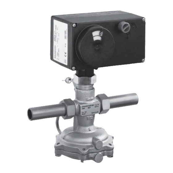
- Page 1 EB 3135-1 EN Translation of original instructions Type 2488/5xxx-x · Type 2488/TROVIS 5xxx-x Pressure-independent Control Valves (PICV) Flow regulators with electric actuators Edition September 2019...
- Page 2 Î For the safe and proper use of these instructions, read them carefully and keep them for later reference. Î If you have any questions about these instructions, contact SAMSON‘s After-sales Service Department (aftersalesservice@samson.de). The mounting and operating instructions for the devices are included in the scope of delivery.
-
Page 3: Table Of Contents
Contents Safety instructions and measures ..............5 Notes on possible severe personal injury ............8 Notes on possible personal injury ..............9 Notes on possible property damage ..............10 Markings on the device ................13 Nameplates ....................13 2.1.1 Nameplate for Type 2488 Valve ..............13 2.1.2 Electric actuator nameplate ................13 Locations of the nameplate ................13 Material numbers ..................14... - Page 4 Contents Operation ....................31 Starting up the plant ..................31 Adjusting the set points .................32 6.4.1 Adjustment of the flow rate ................32 6.4.2 Adjustment without electric actuator ...............32 6.4.3 Adjustment with electric actuator ..............33 6.4.4 Adjusting actuators without fail-safe action ............33 6.4.5 Adjusting actuators with fail-safe action ............34 Servicing.....................37 Replacing the electric actuator ...............39 Replacing the restriction ................40...
-
Page 5: Safety Instructions And Measures
In case operators intend to use the devices in other applications or conditions than specified, contact SAMSON. SAMSON does not assume any liability for damage resulting from the failure to use the de- vice for its intended purpose or for damage caused by external forces or any other external factors. - Page 6 Î Check with the plant operator for details on further protective equipment. Revisions and other modifications Revisions, conversions or other modifications of the product are not authorized by SAMSON. They are performed at the user's own risk and may lead to safety hazards, for example. Furthermore, the product may no longer meet the requirements for its intended use. Warning against residual hazards To avoid personal injury or property damage, plant operators and operating personnel must prevent hazards that could be caused in the regulator by the process medium, the operating pressure or by moving parts by taking appropriate precautions. They must observe all haz-...
- Page 7 Safety instructions and measures Responsibilities of operating personnel Operating personnel must read and understand these mounting and operating instructions as well as the referenced documents and observe the specified hazard statements, warnings and caution notes. Furthermore, the operating personnel must be familiar with the applicable health, safety and accident prevention regulations and comply with them. Referenced standards and regulations The regulators comply with the requirements of the European Pressure Equipment Directive 2014/68/EU. Devices with a CE marking have an EU declaration of conformity, which in-...
-
Page 8: Notes On Possible Severe Personal Injury
Safety instructions and measures 1.1 Notes on possible severe personal injury DANGER Risk of electric shock. Î Before connecting wiring, performing any work on the device or opening the de- vice, disconnect the supply voltage and protect it against unintentional reconnec- tion. Î Only use power interruption devices that are protected against unintentional recon- nection of the supply voltage. -
Page 9: Notes On Possible Personal Injury
WARNING Damage to health relating to the REACH regulation. If a SAMSON device contains a substance which is listed as being a substance of very high concern on the candidate list of the REACH regulation, this circumstance is indi- cated on the SAMSON delivery note. -
Page 10: Notes On Possible Property Damage
The lubricants to be used depend on the regulator material. Unsuitable lubricants may corrode and damage the surface. Î Only use lubricants approved by SAMSON. When in doubt, consult SAMSON. Risk of leakage and regulator damage due to excessively high or low tightening torques. - Page 11 Safety instructions and measures 1.3 Notes on possible property damage NOTICE Incorrect control due to the formation of ice on the regulator. Medium temperatures below 0 °C may cause ice to form on the regulator, depending on the air humidity. This may affect, in particular, the functioning of the plug or dia- phragm stem guide. Î...
- Page 12 Î To loosen and tighten the screws, only use the following screwdrivers: − TORX ® − TORX PLUS 10IP ® − Flat-blade screwdriver with 0.8 mm blade thickness and 4.0 mm blade width Note SAMSON's After-sales Service can support you concerning lubricant, tightening torques and tools approved by SAMSON. EB 3135-1 EN...
-
Page 13: Markings On The Device
Markings on the device 2 Markings on the device Several nameplates are affixed to the device. The nameplates are used to identify the sepa- rate regulator components (see section 2.1). 2.1 Nameplates 2.1.1 Nameplate for Type 2488 Valve Nameplate for Type 2488 Valve 1 Model number and configuration ID Order number or year of manufacture 3 Type designation 4 Flow rate set point range in m³/h Differential pressure at the restriction in bar Max. -
Page 14: Material Numbers
Design and principle of operation 2.3 Material numbers 3 Design and principle of oper- ation 2.3.1 Type 2488 Valve Î See Fig. 3 The material designation can be found on The pressure-independent control valve the cast body or you can contact us (the con- (PICV) consists of the Type 2488 Valve and figuration ID specification is needed) to find an electric actuator. The valve is fitted with a... - Page 15 Design and principle of operation Legend Valve body 6.3 Diaphragm case 1.4 Coupling nut Control line 10.1 Seat Connecting piece 10.2 Guide nipple 8.1 Restriction stem with plug 8.2 Set point adjuster 3.1 Plug balancing Adjustment 3.5 Plug nipple screw 3.6 Seal 8.4 Lead-seal hole Plug stem 8.5 Restriction...
-
Page 16: Technical Data
TROVIS 5xxx Regulators are designed for a u T 3135-1. temperature range from –10 to +150 °C. Noise emission Process medium and scope of application SAMSON is unable to make general state- The Type 2488/5xxx and Type 2488/ ments about noise emissions as they depend TROVIS 5xxx Pressure-independent Control on the valve version, plant facilities and pro- Valves (PICV) are used to control the flow cess medium. - Page 17 Design and principle of operation Table 1: Technical data · Valve · All pressures in bar (gauge) Valve size DN 15/20/25 coefficient 1) 1) 1) Body with screwed ends value Pressure rating PN 16/PN 25 Max. permissible differential pressure 10 bar /20 bar 3) ∆p across the valve For liquids 130 °C (PN 16)/150 °C (PN 25) 6) Max.
- Page 18 Design and principle of operation Table 2: Materials · Material numbers according to DIN EN Body Red brass CC499K (Rg 5) · Spheroidal graphite iron EN-GJS-400-18-LT 1) Seat Stainless steel 1.4305 PN 25 Brass, resistant to dezincification, with EPDM soft seal Plug PN 16 Brass, resistant to dezincification and plastic with EPDM soft seal PN 25 Red brass CC499K (Rg 5) · Spheroidal graphite iron EN-GJS-400-18-LT 1) Diaphragm case PN 16 Stainless steel 1.4301 Valve spring...
- Page 19 Design and principle of operation Table 3: Technical data ∙ Electric actuators Without fail-safe action With fail-safe action Type 5824-…/ Type 5825-…/TROVIS 5725-…/ Electric actuator TROVIS 5724-… TROVIS 5725-7 1) 1) Permissible ambient temperature 0 to +50 °C Perm. medium temperature 0 to +135 °C/150 °C 4) Degree of protection (installed upright, IP 54 according to EN 60529) · Compliance Data sheets See information under ‘Referenced documentation’ on page 7.
- Page 20 Design and principle of operation Table 4: Dimensions and weights in kg Valve size DN 15 DN 20 DN 25 DN 32 DN 40 DN 50 1) 1) 1) Pipe Ø d 21.3 mm 26.9 mm 33.7 mm 42.4 mm 48.3 mm 60.3 mm Thread size R G G 1 G 1¼ G 1 G 2 G 2 ¾ ¾ ½...
- Page 21 Design and principle of operation min. 30 mm min. 30 mm H1 L H1 L Ø116(Ø160) Ø 116 Type 2488/5824 (5825) or TROVIS 5724 (5725) Type 2488/5847 or TROVIS 5757-x with welding ends with welding ends min. 30 mm With screw-on flanges Intermediate insulating piece Type 2488/5824 (5825) or Type 5724 With welding ends With threaded ends...
-
Page 22: Shipment And On-Site Transport
2. Check the shipment for transportation They prevent foreign particles from enter- damage. Report any damage to ing the valve. SAMSON and the forwarding agent Î Dispose and recycle the packaging in ac- (refer to delivery note). cordance with the local regulations. -
Page 23: Storing The Regulator
− Observe the storage instructions. them up. − Avoid long storage times. Î Store elastomers away from lubricants, − Contact SAMSON in case of different stor- chemicals, solutions and fuels. age conditions or long storage periods. − We recommend a storage temperature of 15 °C for elastomers. -
Page 24: Assembly
− The valve is clean. of the regulator. Therefore, we recommend − The valve, actuator and all piping are installing a strainer (e.g. SAMSON not damaged. Type 1 NI) upstream of the regulator. See − Install a strainer upstream of the regula- section 5.3. -
Page 25: Installation Conditions
Assembly 5.2 Installation conditions The minimum differential pressure is calculat- ed as follows: Work position ∙ ) ² ∆p = ∆p + ( V/K The work position for the regulator is the restriction front view onto all operating controls on the Minimum differential pressure across the ∆p regulator (including any additional fittings) -
Page 26: Additional Fittings
A strainer (see Fig. 5) installed upstream in functions properly, follow the installation in- the flow pipe holds back any dirt or other structions given below: foreign particles carried along by the medi- um. For example, the SAMSON Type 1 NI Î Observe the inlet and outlet lengths (see Strainer is suitable (u T 1010). Table 5). Contact SAMSON if the valve conditions or states of the medium pro- − Install the strainer upstream of the regu- cess deviate. - Page 27 Assembly Table 5: Inlet and outlet lengths State of process Valve conditions Inlet Outlet min. min. medium length a length b a x DN b x DN Ma ≤ 0.3 Free of cavitation w < 3 a Inlet length Liquid b Outlet length Cavitation producing noise w ≤ 3 ...
-
Page 28: Start-Up And Operation
Start-up and operation 6 Start-up and operation The prevailing conditions in the plant section affected meet the regulator sizing require- Î See Fig. 3 ments (see information under 'Intended use' 6.1 Start-up on page 5). 6.1.1 Pipeline flushing DANGER Risk of personal injury due to process me- We recommend additionally flushing the dium escaping under pressure. pipeline with installed regulator before start- −... -
Page 29: Pressure Test
8. Check the valve to ensure it functions properly and that there is no leakage. Note The plant operator is responsible for per- forming the pressure test. SAMSON's Af- 6.1.3 Pressure test ter-sales Service can support you to plan All plant components must be designed for and perform a pressure test for your plant. -
Page 30: Mounting The Actuator
(10.2). Observe DIN EN 14597. the tightening torques specified in sec- tion 7.5. SAMSON valves are delivered ready for use. To test the valve's ability to function, the 2. Connect the supply voltage to the electric following quick checks can be performed: actuator (see section 6.1.6). -
Page 31: Operation
Start-up and operation 6.2 Operation Note The regulator is ready for use when mount- Refer to the mounting and operating instruc- ing and start-up have been completed. tions of the electric actuator for more details. See information under ‘Referenced docu- mentation’... -
Page 32: Adjusting The Set Points
Start-up and operation 6.4 Adjusting the set points 6.4.2 Adjustment without elec- tric actuator Î (see Fig. 3) The flow rate can be adjusted either when For valve sizes DN 15 to 25, adjust the flow the electric actuator is mounted on the valve rate by turning the adjustment screw (8.3) at or without a mounted electric actuator. the side using a 4 mm hex wrench. -
Page 33: Adjustment With Electric Actuator
Start-up and operation 6.4.4 Adjusting actuators 3. Based on a closed restriction (screw/ad- juster turned clockwise as far it will go), without fail-safe action adjust the flow set point by turning the screw or adjuster counterclockwise. WARNING Check the flow rate and correct it, if nec- essary. Observe the relevant safety regulations on mounting or removing the electric actuator. 4. Guide the wire through the lead-seal hole and lead-seal it to fix the adjusted 1. -
Page 34: Adjusting Actuators With Fail-Safe Action
Start-up and operation 6.4.5 Adjusting actuators with 1. Switch the control device to manual mode and change the control signal to fail-safe action retract the actuator stem all the way and compress the spring mechanism. WARNING 2. Use a suitable tool (Allen key, SW 4) to Observe the relevant safety regulations on turn the adjustment screw (8.3) or the set mounting or removing the electric actuator. - Page 35 Start-up and operation Table 6: K coefficients and flow rates Valve size DN 25 DN 32 DN 40 DN 50 DN 15 DN 20 1) 1) coefficient 12.5 16/20 16/25 3) 3) 0.8 to 2 to 3 to 4 to Set point range in m³/h 0.6 to 0.8 to – 14.1 with a differential pressure 2) 2)
- Page 36 Start-up and operation Travel in mm DN 32, DN 40, DN 50, Turns 12.5 20/25 Scale marks 0.2 0.3 15 20 m³/h Fig. 7: Flow rate diagram for DN 32 to 50 · Differential pressure at the restriction ∆p = 0.2 bar restriction EB 3135-1 EN...
-
Page 37: Servicing
− If possible, drain the process medium from all the plant sections affected and the valve. SAMSON's After-sales Service can support − Wear protective clothing, safety gloves and you in drawing up an inspection and test eye protection. - Page 38 Parts that are too loose may cause leakage. Observe the tightening torques specified in section 7.5. Note The regulator was checked by SAMSON before it left the factory. − The product warranty becomes void if ser- vice or repair work not described in these...
-
Page 39: Replacing The Electric Actuator
Servicing 7.1 Replacing the electric Note actuator The actuator stem of electric actuators with fail-safe action must be retracted before Î See Fig. 3 mounting or removing the electric actuator. The electric actuator can be replaced while Refer to the mounting and operating instruc- the process is running or after a plant shut- tions of the electric actuator with fail-safe ac- down. -
Page 40: Replacing The Restriction
See information under ‘Referenced documentation’ on page 7. NOTICE DN 15 to 25: unscrew the adjustment screw (8.3) before removing the connecting piece (8). Note SAMSON's After-sales Service can support you concerning lubricant, tightening torques and tools approved by SAMSON. EB 3135-1 EN... - Page 41 Servicing Removing the restriction Mounting the restriction The procedure described below refers to The procedure described below refers to electric actuators without fail-safe action. electric actuators without fail-safe action. 1. Put the regulator out of operation (see 1. Insert the seal (8.7). section 9.1).
-
Page 42: Replacing The Seat And Plug
Servicing 7.3 Replacing the seat and Note plug SAMSON's After-sales Service can support you concerning lubricant, tightening torques and tools approved by SAMSON. NOTICE Risk of regulator damage due to excessively high or low tightening torques. Observe the specified torques on tightening regulator components. - Page 43 Servicing Disassembly Assembly 1. Put the regulator out of operation (see 1. Screw in the seat (2) using a seat section 9.1). wrench. Observe the tightening torques specified in section 7.5. 2. Unscrew the control line (7). 2. Renew the seal (3.6) and insert it into the 3.
-
Page 44: Replacing The Operating Diaphragm
Note SAMSON's After-sales Service can support 1. Check the facings of the valve body (1) you concerning lubricant, tightening torques and the diaphragm case (6.3) for dirt and tools approved by SAMSON. -
Page 45: Tightening Torques
Screws (6.2) DN 40 to 50 Control line connection (7) DN 15 to 50 DN 15 to 25 Connecting piece (8) DN 32 to 50 Coupling nut (10.2) (actuator) DN 15 to 50 7.6 Lubricants and sealants Note SAMSON's After-sales Service can support you concerning lubricants and sealants ap- proved by SAMSON. EB 3135-1 EN... -
Page 46: Preparation For Return Shipment
The malfunctions listed in Table 8 are caused by mechanical faults and incorrect regulator Defective devices can be returned to sizing. In the simplest case, the functioning SAMSON for repair. Proceed as follows to can be restored following the recommended return devices to SAMSON: action. Special tools may be required for re- 1. Put the regulator out of operation (see pair work. - Page 47 Î Clean the control line, needle valve and screw fittings. operating diaphragm. Î Remove foreign particles. Foreign particles blocking the plug Î Replace damaged parts. Î Contact SAMSON's After-sales Service. Flow rate exceeds Î Replace the damaged seat and plug. Seat and plug are worn or leak. adjusted set Î...
-
Page 48: Decommissioning And Removal
Decommissioning and removal 9 Decommissioning and 9.1 Decommissioning removal WARNING Observe the relevant safety regulations on DANGER mounting or removing the electric actuator. Risk of bursting in pressure equipment. Regulators and pipelines are pressure equip- To decommission the regulator for service ment. -
Page 49: Annex
E-mail address You can reach our after-sales service at aftersalesservice@samson.de. Addresses of SAMSON AG and its subsid- iaries The addresses of SAMSON, its subsidiaries, representatives and service facilities world- wide can be found on our website (u www.samson.de) or in all SAMSON... - Page 50 Modul H/Module H, Nr./No. / N° CE-0062-PED-H-SAM 001-16-DEU-rev-A SAMSON erklärt in alleiniger Verantwortung für folgende Produkte:/For the following products, SAMSON hereby declares under its sole responsibility: Ventile für Druck- Differenzdruck-, Volumenstrom- und Temperaturregler/Valves for pressure, differential pressure, volume flow and temperature regulators 2333 (Erz.-Nr./Model No.
- Page 51 Modul H/Module H, Nr./No. / N° CE-PED-H-SAM 001-13-DEU-rev-A SAMSON erklärt in alleiniger Verantwortung für folgende Produkte:/For the following products, SAMSON hereby declares under its sole responsibility: Ventile für Druck-, Differenzdruck-, Temperatur- und Volumenstromregler/Valves for pressure, temperature, flowregulators and differential pressure regulators Typ 2336, 2373, 2375, 44-1B, 44-2, 44-3, 44-4, 44-6B, 44-9, 45-1, 45-2, 45-3, 45-4, 45-6, (Erz.-Nr.
- Page 52 EB 3135-1 EN SAMSON AKTIENGESELLSCHAFT Weismüllerstraße 3 · 60314 Frankfurt am Main, Germany Phone: +49 69 4009-0 · Fax: +49 69 4009-1507 samson@samson.de · www.samson.de...