
Related Manuals for Samson 2405 Series


Summary of Contents for Samson 2405 Series
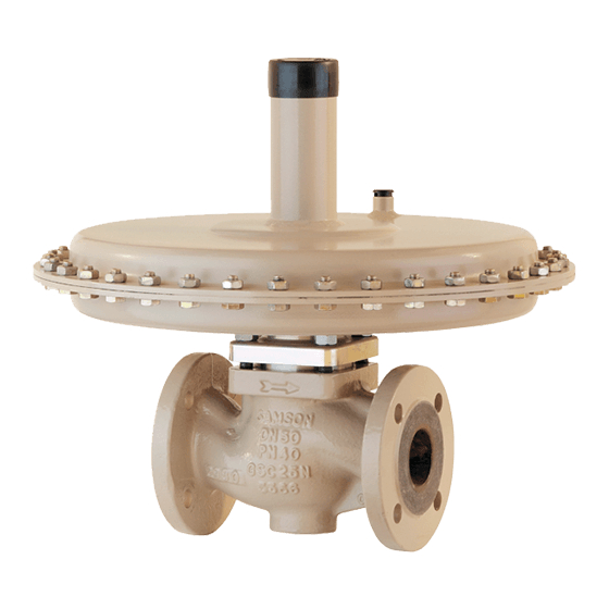
- Page 1 Self-operated Pressure Regulators Type 2405 Pressure Reducing Valve Mounting and Operating Instructions EB 2520 EN Edition June 2017...
- Page 2 Î For the safe and proper use of these instructions, read them carefully and keep them for later reference. Î If you have any questions about these instructions, contact SAMSON‘s After-sales Service Department (aftersalesservice@samson.de). The mounting and operating instructions for the devices are included in the scope of delivery.
-
Page 3: Table Of Contents
Contents Safety instructions and measures ..............5 Notes on possible severe personal injury ............7 Notes on possible personal injury ..............7 Notes on possible property damage ..............8 Markings on the device .................9 Design and principle of operation ..............10 Versions ......................11 Technical data .....................12 Measures for preparation ................16 Unpacking ....................16 Transporting and lifting ................16... - Page 4 Contents Annex......................26 After-sales service ..................26 Certificates ....................26 EB 2520 EN...
-
Page 5: Safety Instructions And Measures
SAMSON. SAMSON does not assume any liability for damage resulting from the failure to use the de- vice for its intended purpose or for damage caused by external forces or any other external factors. - Page 6 Î Check with the plant operator for details on further protective equipment. Revisions and other modifications Revisions, conversions or other modifications to the product are not authorized by SAMSON. They are performed at the user's own risk and may lead to safety hazards, for example. Fur- thermore, the product may no longer meet the requirements for its intended use.
-
Page 7: Notes On Possible Severe Personal Injury
Safety instructions and measures Non-electric valve versions whose bodies are not lined with an insulating material coating do not have their own potential ignition source according to the risk assessment stipulated in EN 13463-1: 2009, section 5.2, even in the rare incident of an operating fault. Therefore, such valve versions do not fall within the scope of Directive 2014/34/EU. -
Page 8: Notes On Possible Property Damage
Î Wear protective clothing and safety gloves. Damage to health relating to the REACH regulation. If a SAMSON device contains a substance which is listed as being a substance of very high concern on the candidate list of the REACH regulation, this circumstance is indi- cated on the SAMSON delivery note. - Page 9 Note Conversion from chromate coating to iridescent passivation We at SAMSON are converting the surface treatment of passivated steel parts in our produc- tion. As a result, you may receive a device assembled from parts that have been subjected to different surface treatment methods.
-
Page 10: Markings On The Device
Markings on the device 2 Markings on the device SAMSON 2009 xxxx Made in Germany Type designation (2405) Nominal size Max. perm. operating pressure at the Nominal pressure actuator p Permissible differential pressure (across Configuration ID the valve) Order number or date Perm. -
Page 11: Design And Principle Of Operation
Design and principle of operation 3 Design and principle of oper- positioning force by the diaphragm plate with operating diaphragm (5). This force is ation used to move the plug stem (4) and the valve The medium flows through the valve in the di- plug depending on the force of the set point rection indicated by the arrow. -
Page 12: Versions
Markings on the device 1 Valve body 7 Set point spring 2 Seat 8 Set point adjuster (screw SW 27) 3 Plug 9 Control line connection, G ¼ fitting 4 Plug stem 10 Balancing diaphragm 5 Diaphragm plate with operating 11 Leakage line connection (special version), diaphragm G ¼... -
Page 13: Technical Data
Markings on the device 3.2 Technical data Table 1: Technical data Nominal size DN 15 DN 20 DN 25 DN 32, 40, 50 Nominal pressure (valve) PN 16 · PN 25 · PN 40 Standard 0.016 · 0.04 0.016 · 0.04 0.016 · 0.04 1.6 · 2.5 · 4 0.1 ·... - Page 14 Markings on the device Table 2: Dimensions in mm Nominal size DN 15 DN 20 DN 25 DN 32 DN 40 DN 50 Length L Forged steel – – Height H2 Other materials Without balancing Height H 5 to 15 mbar With balancing Actuator ØD = 490 mm, A = 1200 cm² Without balancing Height H With balancing...
- Page 15 Markings on the device Dimensional drawings DN 15 to 25 DN 32 to 50 ØD ØD Control line connection G ¼, for A = 40, 80, Control line connection G ¼, for A = 640 and 160, and 320 cm² 1200 cm² The control line connection is turned by 90° in the drawing. The connection is normally located opposite the side with the arrow indicating the direction of flow.
- Page 16 Markings on the device Table 3: Weights in kg Nominal size DN 15 DN 20 DN 25 DN 32 DN 40 DN 50 5 to 15 mbar 10 to 30 mbar 25 to 60 mbar 50 to 200 mbar 0.1 to 0.6 bar 0.2 to 1 bar 0.8 to 2.5 bar 2 to 5 bar 4.5 to 10 bar Body made of cast steel 1.0619: +10 % EB 2520 EN...
-
Page 17: Measures For Preparation
− Observe storage instructions. vice: − Avoid long storage times. 1. Remove the packaging from the device. Contact SAMSON in case of different stor- 2. Dispose of the packaging in accordance age conditions or long storage periods. with the valid regulations. -
Page 18: Preparation For Installation
Measures for preparation than 75 %. In damp spaces, prevent con- densation. If necessary, use a drying agent or heating. − Make sure that the ambient air is free of acids or other corrosive media. − Observe the permissible ambient tem- peratures (see section 3.2). -
Page 19: Mounting And Start-Up
Mounting and start-up 5 Mounting and start-up 5.1.2 Mounting position Standard 5.1 Installing the valve into the Preferably install the regulator in a horizon- pipeline tal pipeline. The actuator housing with set point adjuster must face upwards. 5.1.1 Installation conditions −... -
Page 20: Additional Fittings
Shut-off valve We recommend installing a strainer (e.g. Install a hand-operated shut-off valve both SAMSON Type 2 N) upstream of the regula- upstream of the strainer and downstream of tor. It prevents solid particles in the process the regulator. This allows the plant to be shut medium from damaging the valve. - Page 21 Mounting and start-up Control line NOTICE G ¼ fitting (9) on the actuator housing. Regulator damage due to condensed water. Route control line on site preferably using a In applications in which the gas can liquefy, 8x1 mm (stainless) steel pipe (with min. condensate may form in the control line, 6 mm inside diameter).
-
Page 22: Quick Check
Mounting and start-up 5.2 Quick check Adjusting screw (8), SW 27 Pressure test A pressure test of the plant with the regulator already installed is only permissible up to the nominal pressure of the valve (see Table 1). The pressure at the operating diaphragm must not exceed the maximum permissible Fig. 10: Set point adjustment (view from pressure. - Page 23 Mounting and start-up The pressure gauge (Fig. 7) installed on the downstream side on site allows the adjusted set point to be monitored. EB 2520 EN...
-
Page 24: Servicing
DANGER Note Risk of bursting in pressure equipment. Control valves and pipelines are pressure The device was checked by SAMSON before equipment. Improper opening can lead to it left the factory. valve components bursting. − Certain test results (seat leakage and leak −... -
Page 25: Ordering Spare Parts And Operating Supplies
> Services > Check lists for after sales service > Declaration on Contamination. 4. Send the valve together with the filled-in form to your nearest SAMSON subsidi- ary. SAMSON subsidiaries are listed on our website at u www.samson.de > Contact. -
Page 26: Malfunctions
Improper sizing of the regulator. Check the sizing data used for the regulator. If necessary, change the K coefficient, seat diameter or diaphragm area. Note Contact SAMSON's After-sales Service department for malfunctions not listed in the table. EB 2520 EN... -
Page 27: Decommissioning And Disassembly
Decommissioning and disassembly 8 Decommissioning and disas- 8.1 Decommissioning sembly To decommission the control valve for service and repair work or disassembly, proceed as follows: DANGER Risk of bursting in pressure equipment. 1. Close the shut-off valve on the upstream Control valves and pipelines are pressure side. - Page 28 You can reach the After-sales Service De- partment at aftersalesservice@samson. Addresses of SAMSON AG and its subsid- iaries The addresses of SAMSON AG, its subsid- iaries, representatives, and service facilities worldwide can be found on the SAMSON website or in all SAMSON product catalogs.
- Page 29 Modul H/Module H, Nr./No. / N° CE-0062-PED-H-SAM 001-16-DEU-rev-A SAMSON erklärt in alleiniger Verantwortung für folgende Produkte:/For the following products, SAMSON hereby declares under its sole responsibility: Ventile für Druck- Differenzdruck-, Volumenstrom- und Temperaturregler/Valves for pressure, differential pressure, volume flow and temperature regulators 2333 (Erz.-Nr./Model No.
- Page 30 EB 2520 EN...
- Page 31 EB 2520 EN...
- Page 32 SAMSON AG · MESS- UND REGELTECHNIK Weismüllerstraße 3 · 60314 Frankfurt am Main, Germany Phone: +49 69 4009-0 · Fax: +49 69 4009-1507 EB 2520 EN samson@samson.de · www.samson.de...