
Related Manuals for Samson 2405


Summary of Contents for Samson 2405
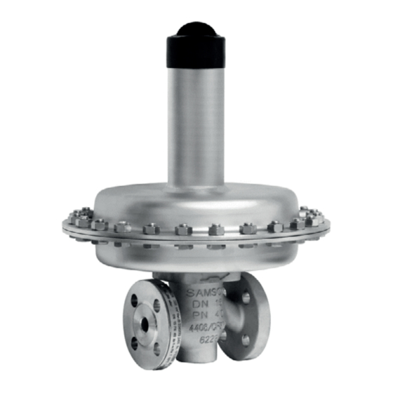
- Page 1 EB 2520 EN Translation of original instructions Type 2405 Pressure Reducing Valve Self-operated Pressure Regulators Edition December 2022...
- Page 2 Note on these mounting and operating instructions These mounting and operating instructions assist you in mounting and operating the device safely. The instructions are binding for handling SAMSON devices. The images shown in these instructions are for illustration purposes only. The actual product may vary.
-
Page 3: Table Of Contents
Contents Safety instructions and measures ..............4 Notes on possible severe personal injury ............7 Notes on possible personal injury ..............8 Notes on possible property damage ..............8 Markings on the device ................10 Regulator nameplate ..................10 Location of the nameplate ................11 2.3 Material identification number ..............11 Design and principle of operation ..............12 Technical data .....................14 Measures for preparation ................19... -
Page 4: Safety Instructions And Measures
In case operators intend to use the device in applications or conditions other than those specified, contact SAMSON. SAMSON does not assume any liability for damage resulting from the failure to use the de- vice for its intended purpose or for damage caused by external forces or any other external factors. - Page 5 These mounting and operating instructions deals with the standard version of the device. Components of the device that differ to those used for the standard version described in this document can be exchanged with other certain SAMSON components. The residual hazards of these components are described in the associated mounting and operating instructions (see documents listed under 'Referenced documentation').
- Page 6 Start-up and shutdown procedures fall within the scope of the operator's duties and, as such, are not part of these mounting and operating instructions. SAMSON is unable to make any statements about these procedures since the operative details (e.g. differential pressures and temperatures) vary in each individual case and are only known to the operator.
-
Page 7: Notes On Possible Severe Personal Injury
Safety instructions and measures Referenced documentation The following documents apply in addition to these mounting and operating instructions: − Mounting and operating instructions for e.g. Type 2 N or 2 NI Strainer u EB 1015 − Data sheets for e.g. Type 2 N or 2 NI Strainer u T 1015 − Mounting and operating instructions as well as data sheets for additional components (e.g. -
Page 8: Notes On Possible Personal Injury
Î Wear protective clothing and safety gloves. Damage to health relating to the REACH regulation. If a SAMSON device contains a substance listed as a substance of very high concern on the candidate list of the REACH regulation, this is indicated on the SAMSON deliv- ery note. Î Information on safe use of the part affected u www.samsongroup.com/en/about- samson/material-compliance/reach-regulation/ 1.3 Notes on possible property damage... - Page 9 Î Always install a safety device (e.g. safety excess pressure valve or safety relief valve) in the plant. Note SAMSON's After-sales Service can support you concerning lubricant, tightening torques and tools approved by SAMSON. EB 2520 EN...
-
Page 10: Markings On The Device
Markings on the device 2 Markings on the device The nameplate shown was up to date at the time of publication of this document. The nameplate on the device may differ from the one shown. 2.1 Regulator nameplate Max. perm. operating Pressure rating 15 CE marking (if applicable) pressure at the actuator... -
Page 11: Location Of The Nameplate
Markings on the device 2.2 Location of the nameplate Location of the nameplate Fig. 2: Nameplate of Type 2405 Regulator 2.3 Material identification number See the nameplate (11, body material). For more details on the nameplate, see sec- tion 2.1. EB 2520 EN... -
Page 12: Design And Principle Of Operation
The downstream pressure p to be controlled pressure. is tapped downstream of the regulator and Fig. 3: Type 2405 Pressure Reducing Valve without pressure balancing · K 1.6 to 4 · Flow-to- open EB 2520 EN... - Page 13 Leakage line connection (special version), phragm G ¼ fitting 6 Actuator housing 12 Cap Fig. 4: Fig. 5: Type 2405 Pressure Reducing Valve Type 2405 Pressure Reducing Valve with without pressure balancing · K pressure balancing · K 6.3 to 32 0.016 to 1 · Flow-to-close EB 2520 EN...
-
Page 14: Technical Data
The regulator is open when relieved of pres- sure. The valve closes when the downstream pressure rises. Note The Type 2405 Regulator is not a safety Temperature range valve. If necessary, a suitable overpressure Depending on how the regulator is config- protection must be installed on site in the ured, it can be used up to temperatures of plant section. - Page 15 Design and principle of operation Dimensions and weights Table 2 provides a summary of the dimensions and weights. The lengths and heights in the dimensional drawings are shown on page 17. Table 1: Technical data Valve size DN 15 DN 20 DN 25 DN 32 DN 40 DN 50 Pressure rating (valve) PN 16 · PN 25 · PN 40 Standard 0.016 · 0.016 · 0.016 · 1.6 · 2.5 · 1.6 · 2.5 · 1.6 · 2.5 · 0.04 · 0.1 · 0.04 · 0.1 · 0.04 · 0.1 · 4.0 · 6.3 · 4.0 · 6.3 · 4.0 · 6.3 · Reduced K 0.25 · 0.4 ·...
- Page 16 Design and principle of operation Table 2: Dimensions in mm Valve size DN 15 DN 20 DN 25 DN 32 DN 40 DN 50 Length L Forged steel – – Height H2 Other materials Without balancing Height H 5 to 15 mbar With balancing Actuator ØD = 485 mm, A = 1200 cm² Without balancing Height H With balancing 10 to 30 mbar ØD = 380 mm,...
- Page 17 Design and principle of operation Dimensional drawings DN 15 to 25 DN 32 to 50 min. 150 mm min. 150 mm ØD ØD Control line connection G ¼, for A = 40, 80, Control line connection G ¼, for A = 640 and 160 and 320 cm² 1200 cm² The control line connection is turned by 90° in the drawing. The connection is normally located opposite the side with the arrow indicating the direction of flow. G ¼ fitting Control line connection at the side of the actuator Control line connection on the bottom of the housing actuator housing Fig. 6: Dimensions of Type 2405 EB 2520 EN...
- Page 18 Design and principle of operation Table 3: Weights in kg 1) Valve size DN 15 DN 20 DN 25 DN 32 DN 40 DN 50 5 to 15 mbar 10 to 30 mbar 25 to 60 mbar 50 to 200 mbar 0.1 to 0.6 bar 0.2 to 1 bar 0.8 to 2.5 bar 2 to 5 bar 4.5 to 10 bar Body made of cast steel 1.0619: +10 % EB 2520 EN...
-
Page 19: Measures For Preparation
Risk of valve damage due to incorrectly at- 2. Check the shipment for transportation tached lifting equipment. damage. Report any damage to Do not attach lifting equipment to mounting SAMSON and the forwarding agent parts (e.g. adjusting screw or control line). (refer to delivery note). 4.1 Unpacking Transport instructions − Protect the device against external influ-... -
Page 20: Storage
− Observe the storage instructions. ing the pipelines in the plant. − Avoid long storage times. Contact SAMSON in case of different stor- Î Ensure that there is no liquid, e.g. con- age conditions or longer storage times. densed water, inside the regulator. If nec- essary, blow out the connecting parts with clean compressed air. -
Page 21: Mounting And Start-Up
Mounting and start-up 5 Mounting and start-up − Make sure the direction of flow matches the direction indicated by the arrow on the body. 5.1 Installing the valve into the − Install the regulator free of stress and pipeline with the least amount of vibrations as possible. -
Page 22: Mounting Orientation
Strainers 5.1.2 Mounting orientation We recommend installing a strainer (e.g. SAMSON Type 2 N) upstream of the regula- Standard tor. It prevents solid particles in the process Preferably install the regulator in a horizon- medium from damaging the valve. tal pipeline. The actuator housing with set Î... - Page 23 Mounting and start-up Control line NOTICE Fitting with G ¼ female thread (9) on the ac- Regulator damage due to condensed water. tuator housing. Route the control line on site In applications in which the gas can liquefy, preferably using a 6 mm or ¼“ (stainless) condensate may form in the control line, steel pipe. causing damage to the regulator. To allow Always connect the control line connection condensate to run back into the tank, install for pressure tapping (see Fig. 7) directly to...
-
Page 24: Quick Check
Mounting and start-up 5.2 Quick check 5.4 Adjusting the set point The regulator in the delivered state does not Pressure test have a defined pressure set point. The set A pressure test of the plant with the regulator point spring is released of tension. The set already installed is only permissible up to the point must be adjusted on starting up the nominal pressure of the valve (see Table 1). -
Page 25: Servicing
Mounting and start-up 6 Servicing NOTICE Incorrect control due to a set point adjuster The regulators do not require much mainte- being turned too far. nance. Nevertheless, they are subject to nat- If the set point adjuster is turned too far, the ural wear, particularly at the seat, plug and regulator becomes blocked and closed-loop operating diaphragm. -
Page 26: Preparation For Return Shipment
2. Decontaminate the valve. Remove any residual process medium. 3. Fill in the Declaration on Contamination. Note The declaration form can be download- The device was checked by SAMSON before ed from our website at it left the factory. u www.samsongroup.com > SERVICE & − Certain test results certified by SAMSON SUPPORT > After-sales Service. -
Page 27: Decommissioning And Removal
Decommissioning and removal 7 Decommissioning and 7.1 Decommissioning removal To decommission the control valve for service and repair work or disassembly, proceed as follows: DANGER Risk of bursting in pressure equipment. 1. Close the shut-off valve on the upstream Valves and pipelines are pressure equip- side. ment. -
Page 28: Disposal
WEEE reg. no.: You can reach our after-sales service at DE 62194439/FR 025665 aftersalesservice@samsongroup.com. Î Observe local, national and internation- Addresses of SAMSON AG and its subsid- al refuse regulations. iaries Î Do not dispose of components, lubricants The addresses of SAMSON AG, its subsid- and hazardous substances together with iaries, representatives and service facilities your other household waste. -
Page 29: Certificates
2016, STATUTORY INSTRUMENTS, compliance with Pressure Equipment 2016 No. 1105 (UKCA marking). It does Directive 2014/68/EU on page 30. not apply to Northern Ireland. − EU declaration of conformity in Importer compliance with Machinery Directive 2006/42/EC for Type 2405 Regulator SAMSON Controls Ltd on page 36. Perrywood Business Park Honeycrock Lane − UKCA declaration of conformity in Redhill, Surrey RH1 5JQ compliance with Directive 2016 Phone: +44 1737 766391 No. 1105 on page 37. - Page 30 DIN EN, body, EN-GJS-400-18-LT and CC499K, DN 50, PN 25, fluids G2, L2, L1 2447 (44-7) 2448 (44-8) 2449 (44-9) Revision 00 Classification: Public · SAMSON AKTIENGESELLSCHAFT · Weismuellerstrasse 3 · 60314 Frankfurt am Main, Germany Page 1 of 3 EB 2520 EN...
- Page 31 Liquids according to Article 4(1)(c.ii) Gases according to Article 4(1)(c.i), second indent Liquids according to Article 4(1)(c.ii), second indent Revision 00 Classification: Public · SAMSON AKTIENGESELLSCHAFT · Weismuellerstrasse 3 · 60314 Frankfurt am Main, Germany Page 2 of 3 EB 2520 EN...
- Page 32 Norbert Tollas i.V. Peter Scheermesser Senior Vice President Director Global Operations Product Maintenance & Engineered Products Revision 00 Classification: Public · SAMSON AKTIENGESELLSCHAFT · Weismuellerstrasse 3 · 60314 Frankfurt am Main, Germany Page 3 of 3 EB 2520 EN...
- Page 33 ANSI, body, A216 WCC and A351 CF8M, NPS 2½-6, Class 150, all fluids ANSI, body, A216 WCC and A351 CF8M, NPS 1½-6, Class 300, all fluids Revision 00 Classification: Public · SAMSON AKTIENGESELLSCHAFT · Weismuellerstrasse 3 · 60314 Frankfurt am Main, Germany Page 1 of 3 EB 2520 EN...
- Page 34 DIN EN, body, EN-GJS-400-18-LT, DN 100-150, PN 25, fluids G2, L2, L1 DIN EN, body, 1.0619, DN 100-250, PN 16, all fluids Revision 00 Classification: Public · SAMSON AKTIENGESELLSCHAFT · Weismuellerstrasse 3 · 60314 Frankfurt am Main, Germany Page 2 of 3 EB 2520 EN...
- Page 35 Norbert Tollas i.V. Peter Scheermesser Senior Vice President Director Global Operations Product Maintenance & Engineered Products Revision 00 Classification: Public · SAMSON AKTIENGESELLSCHAFT · Weismuellerstrasse 3 · 60314 Frankfurt am Main, Germany Page 3 of 3 EB 2520 EN...
- Page 36 Certificates EB 2520 EN...
- Page 37 November 2022 Norbert Tollas Peter Scheermesser Senior Vice President Director Global Operations Product Maintenance & Engineered Products Revision 00 Classification: Public · SAMSON AKTIENGESELLSCHAFT · Weismüllerstrasse 3 · 60314 Frankfurt am Main, Germany Page 1 of 1 EB 2520 EN...
- Page 38 November 2022 Norbert Tollas Peter Scheermesser Senior Vice President Director Global Operations Product Maintenance & Engineered Products Revision 00 Classification: Public · SAMSON AKTIENGESELLSCHAFT · Weismüllerstrasse 3 · 60314 Frankfurt am Main, Germany Page 1 of 1 EB 2520 EN...
- Page 39 Machinery components can be mounted onto the above specified final ma- chinery if they comply with the specifications and properties defined by SAMSON Manual H 02 “Ap- propriate Machinery Components for SAMSON Pneumatic Control Valves with a Declaration of Con- formity of Final Machinery”.
- Page 40 EB 2520 EN SAMSON AKTIENGESELLSCHAFT Weismüllerstraße 3 · 60314 Frankfurt am Main, Germany Phone: +49 69 4009-0 · Fax: +49 69 4009-1507 samson@samsongroup.com · www.samsongroup.com...