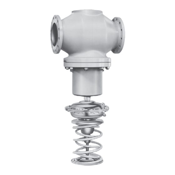
Samson 2422 Mounting And Operating Instructions
Excess pressure valve.
self-operated pressure regulators
Hide thumbs
Also See for 2422:
- Mounting and operating instructions (25 pages) ,
- Mounting and operating instructions (21 pages)

Related Manuals for Samson 2422


Summary of Contents for Samson 2422
- Page 1 Self-operated Pressure Regulators Type 2422/2425 Excess Pressure Valve Type 2422/2425 Excess Pressure Valve Mounting and Operating Instructions EB 2549 EN Edition January 2016...
- Page 2 Definition of signal words DANGER! NOTICE Hazardous situations which, if not Property damage message or mal- avoided, will result in death or serious function injury Note: WARNING! Additional information Hazardous situations which, if not avoided, could result in death or seri- Tip: ous injury Recommended action...
-
Page 3: Table Of Contents
Contents Contents Page General safety instructions ................4 Process medium and scope of application ............5 Transportation and storage ................5 Design and principle of operation ..............6 Installation ....................8 Assembly ......................8 Mounting position ..................9 Notes on installation ..................9 Control line, condensation chamber and needle valve ........10 Strainer .......................11 Shut-off valve ....................11 Pressure gauge ....................11... -
Page 4: General Safety Instructions
General safety instructions General safety instructions − The regulator must be mounted, started up or serviced by fully trained and qualified personnel only; the accepted industry codes and practices are to be observed. Make sure employees or third persons are not exposed to any danger. -
Page 5: Process Medium And Scope Of Application
Process medium and scope of application Process medium and scope of application Pressure regulator for liquids, gases and vapors up to 350 °C For controlling the upstream pressure p to the adjusted set point. The valve opens when the upstream pressure rises. The upstream pressure is transmitted to the actuator over a control line that must be installed on site. -
Page 6: Design And Principle Of Operation
The control of vapors and liquids above justed set point. The valve opens when the up- 150 °C is only possible with a Type 2422 stream pressure rises. Valve balanced by a bellows. In this case,... - Page 7 6.1 Vent screw (640 cm², bellows Bottom diaphragm stem Filling opening with plug Nuts and bolts housing) Upstream pressure 6.2 Vent screw (connection to Downstream pressure Diaphragm plate actuator) Fig. 1: Functional diagram of Type 2422/2425 balanced by a bellows EB 2549 EN...
-
Page 8: Installation
Type 2425 Actuator Balancing diaphragm Upstream pressure Downstream pressure Fig. 2: Functional diagram of Type 2422/2425 balanced by a diaphragm Installation Î Place the actuator on the bellows housing and carefully screw it in as far as it will See Fig. 1 and Fig. 2. -
Page 9: Mounting Position
− Protect the regulator from icing up when cially in applications with gases, air or steam. controlling media that can freeze. If nec- Contact SAMSON to obtain the TV-SK 17041 essary, depressurize and drain the regu- documentation which contains more details on lator and remove it from the pipeline installation requirements. -
Page 10: Control Line, Condensation Chamber And Needle Valve
Installation 4.4 Control line, condensation Mounting position chamber and needle valve Valve balanced by a bellows/diaphragm − Actuator facing downward Control line · A control line must be provided at the site of installation, e.g. a “ pipe for steam or an Ø8 x 1 or Ø6 x 1 mm copper pipe for air or water. -
Page 11: Strainer
This allows the plant to be shut pressure directly at the valve body is available down for cleaning and maintenance, and as an accessories part from SAMSON (for set when the plant is not used for longer periods points ≥ 0.8 bar). See u T 2595. -
Page 12: Operation
The cape from the plant. Install steam trap (e.g. set point range can only be changed by ex- SAMSON Type 13 E) or air vent for steam-op- changing the entire actuator assembly. There- erated systems (e.g. SAMSON Type 3) at a fore, we recommend contacting us if you want suitable location. -
Page 13: Decommissioning
Maintenance and troubleshooting 5.3 Decommissioning The actuator can be removed from the valve without having to remove the valve from the Close first the shut-off valve on the upstream pipeline. However, in this case, do not forget side of the valve and then on the downstream that the actuator cone seals off the bellows side of the valve. -
Page 14: Nameplate
Nameplate Nameplate Nameplates are attached to the valve and the actuator. Valve nameplate DIN version Valve type Model number with index Configuration ID (Var.-ID) Order number or date coefficient DIN version Spring force/set point range Nominal size Nominal pressure Perm. differential pressure Perm. -
Page 15: Customer Service
The addresses of SAMSON AG, its subsidiaries, representatives and service facilities world- wide can be found on the SAMSON website, in all SAMSON product catalogs or on the back of these Mounting and Operating Instructions. Please send your inquiries to: service@samson.de To assist diagnosis, specify the following details (see section 7): −... -
Page 16: Dimensions
(valve with actuator) for cast iron, PN 16 0.05 to 1.0 135 kg 116 kg 286 kg 296 kg 0.5 to 1.5/1 to 2.5 125 kg 110 kg 280 kg 290 kg +10 % for cast steel, spheroidal graphite iron and stainless steel Fig. 5: Dimensions ∙ Type 2422/2424 ∙ Balanced by a bellows EB 2549 EN... - Page 17 Height H 720 mm 745 mm 960 mm 960 mm Height H2 145 mm 175 mm 260 mm 260 mm Weight (actuator with valve), approx. 0.05 to 1 bar 80 kg 94 kg 239 kg 249 kg 0.5 to 2.5 bar 75 kg 88 kg 233 kg 243 kg Fig. 6: Dimensions · Type 2422/2425 ∙ Balanced by a diaphragm EB 2549 EN...
-
Page 18: Technical Data
Technical data 10 Technical data Table 2: Technical data of Type 2422 Valve and Type 2425 Actuator Type 2422 Valve Nominal pressure PN 16, 25 or 40 Nominal size DN 125 DN 150 DN 200 DN 250 Valve balanced by a Metal seal: 350 °C · PTFE soft seal: 220 °C · EPDM or FPM soft seal: bellows 150 °C ·... - Page 19 Conversion from chromate coating to iridescent passivation We at SAMSON are converting the surface treatment of passivated steel parts in our production. As a result, you may receive a device assembled from parts that have been subjected to different surface treatment methods. This means that the surfaces of some parts show different reflections.
- Page 20 SAMSON AG · MESS- UND REGELTECHNIK Weismüllerstraße 3 · 60314 Frankfurt am Main, Germany Phone: +49 69 4009-0 · Fax: +49 69 4009-1507 EB 2549 EN samson@samson.de · www.samson.de...