
Related Manuals for Samson 2489/58 Series


Summary of Contents for Samson 2489/58 Series
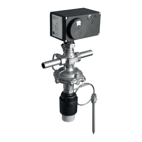
- Page 1 EB 3135-2 EN Translation of original instructions Type 2489/58xx/2430 and Type 2489/57xx/2430 Pressure- independent Control Valves Flow regulators with electric actuator and control thermostat Edition April 2023...
- Page 2 Note on these mounting and operating instructions These mounting and operating instructions assist you in mounting and operating the device safely. The instructions are binding for handling SAMSON devices. The images shown in these instructions are for illustration purposes only. The actual product may vary.
-
Page 3: Table Of Contents
Contents Safety instructions and measures ..............5 Notes on possible severe personal injury ............9 Notes on possible personal injury ..............10 Notes on possible property damage ..............11 Markings on the device ................12 Nameplates ....................12 2.1.1 Nameplate for Type 2489 Valve ..............12 2.1.2 Electric actuator nameplate ................12 Location of the nameplates ................13 2.3... - Page 4 Contents 6.4.1 Adjustment with electric actuator without fail-safe action .........30 6.4.2 Adjustment with electric actuator with fail-safe action ........30 Servicing.....................32 Preparation for return shipment ..............33 Ordering spare parts and operating supplies ..........33 Malfunctions ....................33 Decommissioning and removal ..............35 8.1.1 Decommissioning ..................35 Disposal ......................36 Annex......................37 After-sales service ..................37...
-
Page 5: Safety Instructions And Measures
SAMSON does not assume any liability for damage resulting from the failure to use the device for its intended purpose or for damage caused by external forces or any other external factors. - Page 6 The Type 2489 Pressure-independent Control Valve (PICV) with an electric actuator with fail- safe action moves to a certain fail-safe position upon supply voltage failure. The fail-safe action of SAMSON actuators is specified on the actuator nameplate. When relieved of pressure, the valve with an open restriction without electric actuator and Type 2430 Thermostat is opened by the force of the set point springs.
- Page 7 Start-up and shutdown procedures fall within the scope of the operator's duties and, as such, are not part of these mounting and operating instructions. SAMSON is unable to make any statements about these procedures since the operative details (e.g. differential pressures and temperatures) vary in each individual case and are only known to the operator.
- Page 8 Safety instructions and measures Referenced documentation The following documents apply in addition to these mounting and operating instructions: — u EB 1010 for Type 1 N and Type 1 NI Strainers — u EB 2430 for Type 2430 Control Thermostat — u EB 5724 and for TROVIS 5724-3/-8 or TROVIS 5725-3/-8 Electric Actuators for domestic hot water heating or for heating and cooling applica- u EB 5724-8 tions —...
-
Page 9: Notes On Possible Severe Personal Injury
Safety instructions and measures 1.1 Notes on possible severe personal injury DANGER Risk of fatal injury due to electric shock. Î Before connecting wiring, performing any work on the device or opening the de- vice, disconnect the supply voltage and protect it against unintentional reconnec- tion. Î Only use power interruption devices that are protected against unintentional recon- nection of the power supply. -
Page 10: Notes On Possible Personal Injury
Î Wear protective clothing and safety gloves. Damage to health relating to the REACH regulation. If a SAMSON device contains a substance listed as a substance of very high concern on the candidate list of the REACH regulation, this is indicated on the SAMSON deliv- ery note. Î Information on safe use of the part affected u www.samsongroup.com/en/about-samson/material-compliance/reach-regula-... -
Page 11: Notes On Possible Property Damage
Safety instructions and measures 1.3 Notes on possible property damage NOTICE Risk of valve damage due to contamination (e.g. solid particles) in the pipeline. The plant operator is responsible for cleaning the pipelines in the plant. Î Flush the pipelines before start-up. Î... -
Page 12: Markings On The Device
Markings on the device 2 Markings on the device Several nameplates are affixed to the device. The nameplates shown were up to date at the ones shown. The nameplates are used to the time of publication of this document. The identify the separate regulator components nameplates on the device may differ from (see section 2.1). -
Page 13: Location Of The Nameplates
Markings on the device 2.2 Location of the nameplates Location of the nameplate on the regulator components Fig. 2: Nameplate of the Type 2489 Valve and the electric actuators 2.3 Material identification number 2.3.1 Type 2489 Valve The material designation can be found on the cast body or you can contact us (the con- figuration ID specification is needed) to find out which material is used. -
Page 14: Design And Principle Of Operation
Design and principle of operation 3 Design and principle of oper- ation Î See Fig. 3 Note The flow regulator with connection for For higher temperatures and the resulting additional electric actuator and control thicker insulation of the valve, mount an thermostat consists of the Type 2489 Flow intermediate insulating piece (order no. Regulator, the TROVIS 57xx/Type 58xx 1992-3132) between the connecting piece Electric Actuator and the Type 2430 Control... - Page 15 Design and principle of operation View Z DN 15 to 50 11.1 11.2 Manual adjuster (accessories) Fig. 3: Functional drawings of the regulators (DN 15 to 25) EB 3135-2 EN...
- Page 16 Design and principle of operation Position numbers Valve body 1.1 Welding ends/threaded ends 1.2 Coupling nut Seat Plug Plug stem Set point spring Diaphragm actuator 6.1 Operating diaphragms Coupling nut Connecting piece 8.1 Restriction stem 8.2 Set point adjuster (DN 32 to 50) 8.3 Set point screw (DN 15 to 25) 8.4 Lead-seal hole 8.5 Restriction, unbalanced 8.6 Restriction, balanced by a piston 8.7 Fixing screw 10 Electric actuator...
-
Page 17: Technical Data
IV according to IEC 60534-4. − Non-flammable gases up to 150 °C Noise emissions − Liquids up to 150 °C SAMSON is unable to make general state- The regulator is open when relieved of pres- ments about noise emissions. The noise emis- sure. It closes when the downstream pressure sions depend on the regulator version, plant rises above the adjusted set point. - Page 18 Design and principle of operation Table 1: Technical data for Type 2489 Valve Valve size DN 15 to 25 1) 2) 2) 2) Body with screwed 12.5 ends coef- ficient Flanged — 12.5 body Body with screwed 0.45 ends value Flanged — 0.45 body Pressure rating PN 25 Max.
- Page 19 Design and principle of operation NOTICE − The technical data of the TROVIS 57xx and Type 58xx Electric Actuators are listed in the actuator documentation (Referenced documentation on page 8). − The technical data of the Type 2430 Control Thermostat are listed in the associated docu- mentation (Referenced documentation on page 8).
- Page 20 Design and principle of operation Table 3: Dimensions and weights in kg Valve size 1) 1) 1) Pipe Ø d 21.3 26.9 33.7 42.4 48.3 60.3 Thread size R G ¾ G 1 G 1¼ G 1¾ G 2 G 2½ Width across flats SW Valve size 1) 1) 1) Length L Height H 155 · 158...
- Page 21 Design and principle of operation Dimensional drawings With threaded ends With screw-on flanges Flanged valve body DN 32 to 50 Type 2489 with welding ends/582x-…/2430 Type ... Electric Actuator Dimension X 5725-…, 5825-… 5827-… G½ (G¾) 185 (220) 185 (220) Ø116 (Ø160) Ø12 (Ø19) Ø9,5 (Ø16) Fig. 5: Dimensional drawings EB 3135-2 EN...
-
Page 22: Measures For Preparation
2. Check the shipment for transportation ences (e.g. impact). damage. Report any damage to − Do not damage the corrosion protection SAMSON and the forwarding agent (paint, surface coatings). Repair any (refer to delivery note). damage immediately. − Protect the device against moisture and 4.1 Unpacking... -
Page 23: Storage
− Observe the storage instructions. − We recommend a storage temperature of − Avoid long storage times. 15 °C for elastomers. − Contact SAMSON in case of different stor- − Store elastomers away from lubricants, age conditions or longer storage times. chemicals, solutions and fuels. -
Page 24: Mounting And Start-Up
− The electric actuator must be mounted carried along by the medium. For example, above the valve body. the SAMSON Type 1 NI Strainer is suitable (u T 1010). − Install a strainer upstream of the regula- tor (see section 5.2). − Install the strainer upstream of the regu- lator. -
Page 25: Mounting The Control Thermostat
Mounting and start-up Shut-off valve Î Install a hand-operated shut-off valve both upstream of the strainer and at the outlet of the return flow pipe (see Fig. 6). This allows the plant to be shut down for cleaning and maintenance, and when the plant is not used for longer periods of time. Pressure gauge Install a pressure gauge at a suitable point to monitor the pressures prevailing in the plant... - Page 26 Mounting and start-up Type 2489/5827 Indirectly connected district heating system with Type 2489/5827 Flow Regulator Fig. 6: Sample application EB 3135-2 EN...
-
Page 27: Electrical Connection
Mounting and start-up 5.5 Electrical connection NOTICE The TROVIS 57xx and Type 58xx Electric DANGER Actuators are connected as described in the Risk of fatal injury due to electric shock. actuator documentation (Referenced docu- Î Do not remove any covers to perform mentation on page 8). -
Page 28: Operation
Operation Table 4: Accessories NOTICE Risk of valve damage due to a sudden Accessories Item no. pressure increase and resulting high flow Blanking plug 8323-0030 velocities. Seal 8412-0771 Slowly open the shut-off valve in the pipeline during start-up. Pressure testing the plant 6 Operation All plant components must be designed for the test pressure. -
Page 29: Adjusting The Control Thermostat
Operation NOTICE NOTICE Risk of damage to the restriction stem Risk of regulator damage due to exces- through one-side loading (DN 15 to 25) sively high or low tightening torques. while turning the set point screw (8.3) Observe the specified torques when tighten- clockwise. -
Page 30: Adjustment With Electric Actuator
Operation 4. To fix the flow rate setting in DN 32 to Note 50, tighten the fixing screw (8.7). The The flow rate indicated in the diagram setting must not be fixed in DN 15 to 25. (Fig. 7) is reduced by approximately 20 % 5. Pull the wire through the lead-seal hole for valves in sizes DN 32 to 50 which are (8.4) and lead-seal it. - Page 31 Testing according to case cover. Place a 4 mm hex wrench on the DIN EN 14597 red actuating shaft and turn it. Various SAMSON electric actuators with Turn it only counterclockwise and only up to fail-safe action "actuator stem extends" are the point at which the torque switch in the tested by the German technical surveillance actuator is activated.
-
Page 32: Servicing
− If possible, drain the process medium from all the plant sections affected and the SAMSON's After-sales Service can support valve. you in drawing up an inspection and test − Wear protective clothing, safety gloves and plan for your plant. -
Page 33: Preparation For Return Shipment
Malfunctions 7.2 Ordering spare parts and Note operating supplies The regulator was checked by SAMSON be- fore delivery. Contact your nearest SAMSON subsidiary − The product warranty becomes void if ser- or SAMSON's After-sales Service for infor- vice or repair work not described in these mation on spare parts, lubricants and tools. - Page 34 Recalculate K and contact Control loop hunts. Valve too large for control task SAMSON for further action. Note Contact SAMSON's After-sales Service for malfunctions not listed in the table and when the malfunction cannot be remedied as described. EB 3135-2 EN...
-
Page 35: Decommissioning And Removal
Malfunctions 8.1 Decommissioning and WARNING removal Risk of personal injury due to residual pro- cess medium in the regulator. DANGER While working on the regulator, residual Risk of bursting in pressure equipment. process medium can escape and, depending Regulators and pipelines are pressure equip- on its properties, may lead to personal in- ment. -
Page 36: Disposal
Malfunctions 8.2 Disposal SAMSON is a producer registered at the following European institution u https:// www.ewrn.org/national- registers/national-registers. WEEE reg. no.: DE 62194439/FR 025665 Î Observe local, national and internation- al refuse regulations. Î Do not dispose of components, lubricants and hazardous substances together with your other household waste. -
Page 37: Annex
Coupling nut (1.2) E-mail address DN 32 You can reach our after-sales service at DN 40 aftersalesservice@samsongroup.com. DN 50 Addresses of SAMSON AG and its subsid- Coupling nut (7) iaries Screw joint with restriction (11.1) The addresses of SAMSON, its subsidiaries, representatives and service facilities Screw fitting (11.2) worldwide can be found on our website (u www.samsongroup.com) or in all... -
Page 38: Certificates
Certificates 10 Certificates The EU declarations of conformity are in- cluded on the next pages: − EU declaration of conformity in compli- ance with Pressure Equipment Directive 2014/68/EU on page 39. − EU declaration of conformity in compli- ance with Machinery Directive 2006/42/EC for Type 2489 Regulator on page 40. - Page 39 Certificates EB 3135-2 EN...
- Page 40 DIN EN, body, EN-GJS-400-18-LT and CC499K, DN 50, PN 25, fluids G2, L2, L1 2447 (44-7) 2448 (44-8) 2449 (44-9) Revision 00 Classification: Public · SAMSON AKTIENGESELLSCHAFT · Weismuellerstrasse 3 · 60314 Frankfurt am Main, Germany Page 1 of 3 EB 3135-2 EN...
- Page 41 Liquids according to Article 4(1)(c.ii) Gases according to Article 4(1)(c.i), second indent Liquids according to Article 4(1)(c.ii), second indent Revision 00 Classification: Public · SAMSON AKTIENGESELLSCHAFT · Weismuellerstrasse 3 · 60314 Frankfurt am Main, Germany Page 2 of 3 EB 3135-2 EN...
- Page 42 Norbert Tollas i.V. Peter Scheermesser Senior Vice President Director Global Operations Product Maintenance & Engineered Products Revision 00 Classification: Public · SAMSON AKTIENGESELLSCHAFT · Weismuellerstrasse 3 · 60314 Frankfurt am Main, Germany Page 3 of 3 EB 3135-2 EN...
- Page 43 Certificates EB 3135-2 EN...
- Page 44 EB 3135-2 EN SAMSON AKTIENGESELLSCHAFT Weismüllerstraße 3 · 60314 Frankfurt am Main, Germany Phone: +49 69 4009-0 · Fax: +49 69 4009-1507 samson@samsongroup.com · www.samsongroup.com...