
Related Manuals for Samson 2373


Summary of Contents for Samson 2373
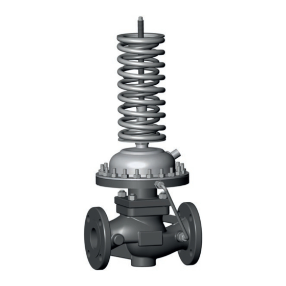
- Page 1 EB 2534 EN Translation of original instructions Type 2373 Universal Pressure Reducing Valve Edition May 2023...
- Page 2 Note on these mounting and operating instructions These mounting and operating instructions assist you in mounting and operating the device safely. The instructions are binding for handling SAMSON devices. The images shown in these instructions are for illustration purposes only. The actual product may vary.
-
Page 3: Table Of Contents
Contents Safety instructions and measures ..............5 Notes on possible severe personal injury ............8 Notes on possible personal injury ..............8 Notes on possible property damage ..............9 Markings on the device ................11 2.1 Material identification number ..............11 Design and principle of operation ..............12 Technical data .....................12 Measures for preparation ................17 Unpacking ....................17 Transporting and lifting ................17... - Page 4 Contents Annex......................33 10.1 After-sales service ..................33 Certificates ....................33 EB 2534 EN...
-
Page 5: Safety Instructions And Measures
In case operators intend to use the devices in applications or conditions other than those specified, contact SAMSON. SAMSON does not assume any liability for damage resulting from the failure to use the de- vice for its intended purpose or for damage caused by external forces or any other external factors. - Page 6 Î Wear hearing protection when working near the valve. Follow the instructions given by the plant operator. Î Check with the plant operator for details on further protective equipment. Revisions and other modifications Revisions, conversions or other modifications of the product are not authorized by SAMSON. They are performed at the user's own risk and may lead to safety hazards, for example. Fur- thermore, the product may no longer meet the requirements for its intended use. Warning against residual hazards...
- Page 7 Start-up and shutdown procedures fall within the scope of the operator's duties and, as such, are not part of these mounting and operating instructions. SAMSON is unable to make any statements about these procedures since the operative details (e.g. differential pressures and temperatures) vary in each individual case and are only known to the operator.
-
Page 8: Notes On Possible Severe Personal Injury
Safety instructions and measures Referenced documentation The following documents apply in addition to these mounting and operating instructions: − Mounting and operating instructions for additional components, such as strainers (e.g. Type 2NI Strainer u EB 1015) 1.1 Notes on possible severe personal injury DANGER Risk of bursting in pressure equipment. Regulators and pipelines are pressure equipment. -
Page 9: Notes On Possible Property Damage
Î Wear protective clothing and safety gloves. Damage to health relating to the REACH regulation. If a SAMSON device contains a substance listed as a substance of very high concern on the candidate list of the REACH regulation, this is indicated on the SAMSON delivery note. - Page 10 Risk of regulator damage due to the use of unsuitable sealants or lubricants. The sealants and lubricants to be used depend on the regulator material. Unsuitable sealants and lubricants may corrode and damage surfaces. Î Only use sealants and lubricants approved by SAMSON (see section 7.3). Incorrect control due to the formation of ice on the regulator. Medium temperatures below 0 °C may cause ice to form on the regulator, depending on the air humidity.
-
Page 11: Markings On The Device
Markings on the device 2 Markings on the device Specifications on SAMSON 2009 the regulator flange xxxx Made in Germany Type Max. perm. operating pressure at the actuator p Configuration ID Order number/date coefficient Set point range/spring force Valve size DN Pressure rating PN Perm. differential pressure Δp in bar... -
Page 12: Design And Principle Of Operation
Design and principle of operation 3 Design and principle of 3.1 Technical data operation Process medium and scope of application (see Fig. 2) Type 2373 Universal Pressure Reducing The medium flows through the valve body (1) Valve to control the downstream pressure p as indicated by the arrow. The position of in applications with seawater. the plug (3) determines the flow rate across For pressure ranges from 0.8 to 16 bar ·... - Page 13 12 Operating diaphragm Plug stem 13 Nut and bolt Spring plate Upstream pressure p 14 Control line Set point adjuster Downstream pressure p 15 Screw fitting Set point springs Fig. 2: Functional diagram of Type 2373 Universal Pressure Reducing Valve EB 2534 EN...
- Page 14 Design and principle of operation Table 1: Technical data · All pressure stated as gauge pressure Valve Valve size DN 15 to 50 1) Pressure rating PN 40 Max. permissible temperature 80 °C 2) Max. permissible ambient temperature 80 °C Metal seal ≤0.05 % of K coefficient (Class I) Leakage class according to IEC 60534-4 Soft seal ≤0.01 % of K coefficient (Class IV)
- Page 15 Design and principle of operation Table 3: K coefficients and max. permissible differential pressures Δp Valve size coefficients Max. permissible differential pressures Δp Standard version Special version Standard version Special version DN 15 DN 20 1 · 2.5 10 bar 14 bar DN 25 DN 32 16.0 8 bar 10.0 10 bar DN 40 20.0...
- Page 16 Design and principle of operation Dimensions ØD Fig. 3: Dimensions of Type 2373 EB 2534 EN...
-
Page 17: Measures For Preparation
2. Check the shipment for transportation WARNING damage. Report any damage to Risk of lifting equipment tipping over and SAMSON and the forwarding agent risk of damage to lifting accessories due to (refer to delivery note). exceeding the rated lifting capacity. -
Page 18: Transporting
Measures for preparation 4.2.1 Transporting 4.2.2 Lifting The regulator can be transported using lifting To install a large regulator into the pipeline, equipment (e.g. crane or forklift). use lifting equipment (e.g. crane or forklift) to lift it. Î Leave the regulator in its transport con- tainer or on the pallet to transport it. -
Page 19: Storage
− Observe the storage instructions. − Avoid long storage times. − Contact SAMSON in case of different stor- age conditions or longer storage times. Note We recommend to regularly check the device and the prevailing storage conditions during long storage periods. -
Page 20: Preparation For Installation
Î Check the regulator to make sure that it is clean. Î Check the regulator for damage. SAMSON's After-sales Service can provide Î Check to make sure that the type desig- more detailed storage instructions on re- nation, valve size, material, pressure rat- quest. -
Page 21: Mounting And Start-Up
Mounting and start-up 5 Mounting and start-up 5.1 Mounting positions See Fig. 5 for permissible mounting posi- NOTICE NOTICE tions. Risk of overheating due to excessive ambi- Standard mounting position ent temperatures or insufficient heat dissi- Install the regulator in a horizontal pipeline pation when components are insulated. with the set point springs facing upward. −... -
Page 22: Installing The Regulator Into The Pipeline
Mounting and start-up 5.2 Installing the regulator into Î Observe the inlet and outlet lengths (see Table 5). Contact SAMSON if the regula- the pipeline tor conditions or state of the medium process deviate. 5.2.1 Checking the installation Î Install the regulator free of stress and... -
Page 23: Additional Fittings
In strainers where the medium flows up- ward, the cover and filter face upward. Shut-off valve for upstream Type 2373 Universal Shut-off valve for down- pressure Pressure Reducing Valve stream pressure Strainer Downstream pressure gauge Safety valve Upstream pressure gauge Fig. 6: Installation example for Type 2373 Universal Pressure Reducing Valve EB 2534 EN... -
Page 24: Installing The Regulator
Mounting and start-up 5.2.3 Installing the regulator 5.3 Start-up 1. Close the shut-off valves in the pipeline DANGER while the valve is being installed. Risk of personal injury due to process me- 2. Remove the protective caps from the dium escaping. flanges before installing the valve. -
Page 25: Operation
Operation 6 Operation Pressure testing the plant All plant components must be designed for 6.1 Adjusting the set points the test pressure. Remove the regulator from the pipeline, if necessary. Note NOTICE Turning the set point adjuster (6) Risk of damage to the actuator diaphragm −... -
Page 26: Servicing
Servicing 7 Servicing WARNING The regulator does not require much mainte- Risk of burn injuries due to hot or cold com- nance. Nevertheless, it is subject to natural ponents and pipelines. wear, particularly at the seat, plug and oper- Depending on the process medium, regula- ating diaphragm. -
Page 27: Replacing The Operating Diaphragm
Servicing 7.1 Replacing the operating di- Note aphragm The regulator was checked by SAMSON be- fore delivery. See Fig. 2. − The product warranty becomes void if If the downstream pressure deviates consid- service work not described in these erably from the set point, check if the dia- instructions is performed without prior phragm is leaking. -
Page 28: Replacing The Set Point Springs
Servicing 7.2 Replacing the set point Mount the operating diaphragm as follows: springs 1. Insert the operating diaphragm into the actuator housing onto the bottom dia- Î See Fig. 2 phragm plate (16). 2. Place on the top diaphragm plate (17) Removing the set point springs and screw on the nut (18) while holding 1. -
Page 29: Tightening Torques And Lubricant
Servicing 7.3 Tightening torques and 7.4 Preparation for return ship- lubricant ment See Fig. 2. Defective devices can be returned to SAMSON for repair. Proceed as follows to Actuator area Tightening Component return devices to SAMSON: in cm² torque in Nm 1. Put the regulator out of operation (see Screws (13) 40 · 80 · 160... -
Page 30: Malfunctions
For troubleshooting, the condi- tions, such as installation, process medium, temperature and pressure conditions, must be taken into account. SAMSON's After-sales Service can help during troubleshooting. Further information is available in section 10.1. Note Contact SAMSON's After-sales Service for... - Page 31 Malfunctions Table 6: Troubleshooting Malfunction Possible reasons Recommended action Î Remove foreign particles. Foreign particles blocking the plug Î Replace damaged parts. Insufficient pressure pulses on the Î Clean the control line and screw fittings. operating diaphragm. Î Check the sizing. Regulator or K coefficient too Î Change K coefficient, if necessary Downstream pressure p large or install a different sized regulator.
-
Page 32: Decommissioning And Removal
While working on the regulator and control 9.2 Disposal line, residual process medium can escape and, depending on its properties, may lead SAMSON is a producer to personal injury, e.g. (chemical) burns. registered at the following Wear protective clothing, safety gloves and European institution u https://www.ewrn.org/... - Page 33 E-mail address You can reach our after-sales service at aftersalesservice@samsongroup.com. Addresses of SAMSON AG and its subsid- iaries The addresses of SAMSON, its subsidiaries, representatives and service facilities worldwide can be found on our website (u www.samsongroup.com) or in all...
- Page 34 DIN EN, body, EN-GJS-400-18-LT and CC499K, DN 50, PN 25, fluids G2, L2, L1 2447 (44-7) 2448 (44-8) 2449 (44-9) Revision 00 Classification: Public · SAMSON AKTIENGESELLSCHAFT · Weismuellerstrasse 3 · 60314 Frankfurt am Main, Germany Page 1 of 3 EB 2534 EN...
- Page 35 Liquids according to Article 4(1)(c.ii) Gases according to Article 4(1)(c.i), second indent Liquids according to Article 4(1)(c.ii), second indent Revision 00 Classification: Public · SAMSON AKTIENGESELLSCHAFT · Weismuellerstrasse 3 · 60314 Frankfurt am Main, Germany Page 2 of 3 EB 2534 EN...
- Page 36 Norbert Tollas i.V. Peter Scheermesser Senior Vice President Director Global Operations Product Maintenance & Engineered Products Revision 00 Classification: Public · SAMSON AKTIENGESELLSCHAFT · Weismuellerstrasse 3 · 60314 Frankfurt am Main, Germany Page 3 of 3 EB 2534 EN...
- Page 37 ANSI, body, A216 WCC and A351 CF8M, NPS 2½-6, Class 150, all fluids ANSI, body, A216 WCC and A351 CF8M, NPS 1½-6, Class 300, all fluids Revision 00 Classification: Public · SAMSON AKTIENGESELLSCHAFT · Weismuellerstrasse 3 · 60314 Frankfurt am Main, Germany Page 1 of 3 EB 2534 EN...
- Page 38 DIN EN, body, EN-GJS-400-18-LT, DN 100-150, PN 25, fluids G2, L2, L1 DIN EN, body, 1.0619, DN 100-250, PN 16, all fluids Revision 00 Classification: Public · SAMSON AKTIENGESELLSCHAFT · Weismuellerstrasse 3 · 60314 Frankfurt am Main, Germany Page 2 of 3 EB 2534 EN...
- Page 39 Norbert Tollas i.V. Peter Scheermesser Senior Vice President Director Global Operations Product Maintenance & Engineered Products Revision 00 Classification: Public · SAMSON AKTIENGESELLSCHAFT · Weismuellerstrasse 3 · 60314 Frankfurt am Main, Germany Page 3 of 3 EB 2534 EN...
- Page 40 EB 2534 EN SAMSON AKTIENGESELLSCHAFT Weismüllerstraße 3 · 60314 Frankfurt am Main, Germany Phone: +49 69 4009-0 · Fax: +49 69 4009-1507 samson@samsongroup.com · www.samsongroup.com...