Table of Contents
Advertisement
Model No. WESY39100
Serial No.
Write the serial number in the
space above for reference.
Serial Number Decal (Under Seat)
QUESTIONS?
As a manufacturer, we are com-
mitted to providing complete
customer satisfaction. If you have
questions, or if there are missing
parts, we will guarantee complete
satisfaction through assistance
from our factory.
TO AVOID UNNECESSARY
DELAYS, PLEASE CALL DIRECT
TO OUR TOLL-FREE CUSTOMER
HOT LINE. The trained techni-
cians on our customer hot line
will provide immediate assis-
tance, free of charge to you.
CUSTOMER HOT LINE:
1-800-999-3756
Mon.ÐFri., 6 a.m.Ð6 p.m. MST
CAUTION
Read all precautions and instruc-
tions in this manual before using
this equipment. Save this manual
for future reference.
USER'S MANUAL
Patent Pending
Visit our website at
www.weiderfitness.com
new products, prizes,
fitness tips, and much more!
Advertisement
Table of Contents

Related Manuals for Weider PRO 9400


Summary of Contents for Weider PRO 9400
- Page 1 Model No. WESY39100 Serial No. Write the serial number in the space above for reference. Serial Number Decal (Under Seat) QUESTIONS? As a manufacturer, we are com- mitted to providing complete customer satisfaction. If you have questions, or if there are missing parts, we will guarantee complete satisfaction through assistance from our factory.
-
Page 2: Table Of Contents
Remove the PART IDENTIFICATION CHART and the PART LIST/EXPLODED DRAWING before beginning assembly. WEIDER is a registered trademark of ICON Health & Fitness, Inc. ICON Health & Fitness, Inc. (ICON), warrants this product to be free from defects in workmanship and material, under normal use and service conditions, for a period of ninety (90) days from the date of pur- chase. -
Page 3: Important Precautions
IMPORTANT PRECAUTIONS WARNING: To reduce the risk of serious injury, read the following important precautions before using the home gym system. 1. It is the responsibility of the owner to ensure that all users of the home gym system are adequately informed of all precautions. -
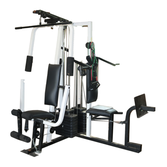
Page 4: Components View
Whether your goal is to tone your body, build dramatic muscle size and strength, or improve your cardiovascular system, the PRO 9400 will help you to achieve the specific results you want. For your benefit, read this manual carefully before using the WEIDER ¨... -
Page 5: Assembly
ASSEMBLY Before beginning assembly, carefully read the following information and instructions: ¥ Due to the many features of the home gym system, assembly will require about six hours. By setting aside plenty of time and by deciding to make the task enjoyable, assembly will go smoothly. - Page 6 2. Slide the Rear Upright (74) and the Leg Press Upright (56) onto the indicated 5/16Ó x 2 1/2Ó Carriage Bolts (1) in the Stabilizer (5). The high side of the brackets on the Rear Upright and Leg Press Upright should be on the side shown.
- Page 7 4. Press a 2Ó Square Inner Cap (27) into the end of the Top Frame (55). Press a 1 3/4Ó Square Inner Cap (44) into each end of the crossbar on the Top Frame. Press two 1Ó Round Inner Caps (75) into the top of the crossbar. Attach the Top Frame (55) to the Rear Upright (74) and the Leg Press Upright (56) with two 5/16Ó...
- Page 8 7. Press a Weight Tube Bumper (64) into the end of a Weight Tube (63). Insert the Weight Tube into the front stack of Weights (25). Be sure that the pin on the Weight Tube is sit- ting in the pin grooves in the top Weight. Lubricate the inside of the holes in the Top Weight (65).
-
Page 9: Arm Assembly
9. Attach the upper ends of the Short Weight Guides (73) to the Top Frame (55) with a 5/16Ó x 6Ó Bolt (60), two 1/2Ó x 3/4Ó Spacers (61), and a 5/16Ó Nylon Locknut (3). Attach the upper ends of the Long Weight Guides (62) to the Top Frame (55) with a 5/16Ó... - Page 10 12. Press a 1Ó Round Inner Cap (49) into one of the Press Arms (46). Press a 1 3/4Ó Square Inner Cap (44) into the Press Arm. Attach the Press Arm (46) to one side of the Press Frame (17) with two 5/16Ó x 2 1/2Ó Bolts (22) and two 5/16Ó...
-
Page 11: Cable Assembly
15. See the inset drawing. Attach the Military Press Arm (84) to the Pivot Arm (80) with two 5/16Ó x 2 1/4Ó Bolts (33) and two 5/16Ó Nylon Locknuts (3). Press two 1 1/2Ó Square Inner Caps (32) into the indicated end of the Military Press Arm (84). - Page 12 18. Wrap the High Cable (58) around a ÒVÓ-Pulley (50). Attach the ÒVÓ-Pulley and a Long Cable Trap (31) to the indicated bracket on the Front Upright (42) with a 3/8Ó x 2 1/2Ó Bolt (86) and a 3/8Ó Nylon Locknut (21). Be sure that the Long Cable Trap is positioned to hold the Cable in place.
- Page 13 22. See the inset drawing. Attach a 3 1/2Ó Pulley (15) and a Cable Trap (66) to the upper hole in a Long ÒUÓ-Bracket (57) with a 3/8Ó x 2Ó Bolt (12) and a 3/8Ó Nylon Locknut (21). Be sure that the Cable Trap is inside the Long ÒUÓ- Bracket.
- Page 14 25. Locate the Low Cable (23) and the bag labeled ÒLOW PULLEY.Ó Route the Low Cable under the 3 1/2Ó Low Pulley (76). Attach the Pulley and the 5/8Ó x 9/16Ó Spacer (7) to the Press Frame (17) with a 3/8Ó x 3 3/4Ó...
- Page 15 29. Attach the end of the Low Cable (23) to the Long ÒUÓ-Bracket (57) with a 1/4Ó Nylon Locknut (2) and a 1/4Ó Flat Washer (10). You may need to lift the Top Weight (not shown) on the High Cable to get enough slack to attach the Low Cable to the Long ÒUÓ-Bracket.
- Page 16 32. Wrap the Military Press Cable (72) around a 3 1/2Ó Pulley (15). Attach the Pulley and a Cable Trap (66) to the Pivot Arm (80) with the 3/8Ó x 5Ó Bolt (101). Be sure the Bolt is on the side shown, and that the Cable Trap is positioned to hold the Cable in place.
- Page 17 35. Locate the Leg Press Cable (78). Attach the end of the Leg Press Cable to the Long ÒUÓ- Bracket (57) with a 1/4Ó Nylon Locknut (2) and a 1/4Ó Flat Washer (10). Do not completely tighten the Nylon Locknut. It should be threaded onto the end of the Cable only a couple of turns, as shown in the inset drawing.
- Page 18 37. Locate and open the parts bag labeled ÒSEAT ASSEMBLY.Ó Insert a 1/4Ó x 2 1/2Ó Carriage Bolt (92) through the center hole in a Seat Plate (37). Attach the Seat Plate to the Leg Press Backrest (85) with two 1/4Ó x 1/2Ó Screws (18). Insert the 1/4Ó...
- Page 19 41. Press a 1 1/2Ó Square Inner Cap (32) into the Leg Lever (29). Lubricate the 5/16Ó x 2 1/4Ó Bolt (33). Attach the Leg Lever (29) to the Front Seat Frame (36) with the Bolt and a 5/16Ó Nylon Locknut (3).
- Page 20 44. Remove the adhesive backing from the PRO 9400 decal and apply it to the Front Upright (42) under the ÒWEIDERÓ nameplate as shown. 45. Make sure that all parts have been properly tightened. The use of the remaining parts will be explained in HOW TO USE THE HOME GYM SYSTEM, beginning on page 21 of this manual.
-
Page 21: How To Use The Home Gym System
HOW TO USE THE HOME GYM SYSTEM The instructions below describe how each part of the home gym system can be adjusted. Refer to the exercise poster accompanying this manual to see how the home gym system should be set up for each exercise. IMPORTANT: When attaching the lat bar or nylon strap, make sure that the attachments are in the cor- rect starting position for the exercise to be performed. - Page 22 ATTACHING AND REMOVING THE SEAT To attach the Seat (13), set the bracket on the Front Seat Frame (36) onto the indicated pins on the Front Upright (42). Attach the Seat Frame to the Front Upright with the 5/16Ó x 2 3/4Ó Carriage Bolt (14), 3/16Ó...
-
Page 23: Weight Resistance Chart
WEIGHT RESISTANCE CHART This chart shows the approximate weight resistance at each weight station. ÒTopÓ refers to the 6.5 lb. top weight. The other numbers refer to the 12.5 lb. weight plates. The butterfly arm resistance listed is the resistance for each butterfly arm. -
Page 24: Trouble-Shooting And Maintenance
TROUBLE-SHOOTING AND MAINTENANCE Inspect and tighten all parts each time you use the home gym system. Replace any worn parts immediately. The home gym system can be cleaned using a damp cloth and mild non-abrasive detergent. Do not use solvents. TIGHTENING THE CABLES Woven cable, the type of cable used on the home gym system, can stretch slightly when it is first used. -
Page 25: Cable Diagrams
CABLE DIAGRAMS The cable diagrams on these pages show the proper routing of the High Cable (58), the Low Cable (23), the Military Press Cable (72), and the Leg Press Cable (78). Use the diagrams to be sure that the four cables and the cable traps have been assembled correctly. - Page 26 Military Press Cable (72) and Leg Press Cable (78) Military Press Cable (72) Ball End 1ÑLong ÒUÓ-Bracket Rear Weight StackÑ1 4ÑRear Seat Frame Leg Press Cable (78)
- Page 27 NOTES...
- Page 28 1/4" Nylon Locknut (2) 1/4" x 2" Machine Screw (81) 5/16" Nylon Locknut (3) 5/16" x 2 1/2" Bolt (22) 5/16" Nylon Jam Nut (93) 3/8" Nylon Jam Nut (99) 3/8" x 2" Bolt (12) 3/8" Nylon Locknut (21) 5/16" x 2 1/4" Bolt (33) 1/4"...
- Page 29 1/4" x 3/4" Screw (18) 3/8" x 3 1/4" Bolt (67) #8 x 1/2" Self-tapping Screw (87) 3/8" x 3 1/2" Bolt (16) 3/8" x 3 3/4" Bolt (88) 5/16" x 5" Bolt (68) Cable Clip (53) 1" Retainer (69) 1 1/8"...
- Page 30 1/2" x 3/4" Spacer (61) 5/16" x 2" Eyebolt (35) 3/4" Round Inner Cap (34) 1" Round Inner Cap (49) 1" Round Cover Cap (70) 1" Square Inner Cap (6) 1 3/4" Square Inner Cap (44) 1 1/2" Square Inner Cap (32) 2"...
- Page 31 PART LISTÑModel No. WESY39100 Key No. Qty. Description 5/16Ó x 2 1/2Ó Carriage Bolt 1/4Ó Nylon Locknut 5/16Ó Nylon Locknut Base Stabilizer 1Ó Square Inner Cap 5/8Ó x 9/16Ó Spacer 5/16Ó Flat Washer 3/8Ó Flat Washer 1/4Ó Flat Washer 5/16Ó x 2 3/4Ó Bolt 3/8Ó...
-
Page 33: Ordering Replacement Parts
Friday, 6 a.m. until 6 p.m. Mountain Time (excluding holidays). To help us assist you, please be pre- pared to give the following information: 1. The MODEL NUMBER of the product (WESY39100). 2. The NAME of the product (WEIDER ¨ PRO 9400 home gym system).