Advertisement
Model No. 831.159720
Serial No.
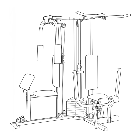
The serial number is found in the
location shown below. Write the
serial number in the space above.
SEARS, ROEBUCK AND CO.
HOFFMAN ESTATES, IL 60179
CAUTION
Read all precautions and instruc-
tions in this manual before using
this equipment. Save this manu-
al for future reference.
Serial
Number
Decal
®
USER'S MANUAL
www.weiderfitness.com
fitness tips, and much more!
Patent Pending
Visit our website at
new products, prizes,
Advertisement
Table of Contents

Related Manuals for Weider 831.159720


Summary of Contents for Weider 831.159720
- Page 1 Model No. 831.159720 Serial No. The serial number is found in the location shown below. Write the serial number in the space above. Serial Number Decal SEARS, ROEBUCK AND CO. HOFFMAN ESTATES, IL 60179 CAUTION Read all precautions and instruc- tions in this manual before using this equipment.
-
Page 2: Table Of Contents
Table of Contents Important Precautions ..............3 Before You Begin . -
Page 3: Important Precautions
Important Precautions WARNING: To reduce the risk of serious injury, read the following important precau- tions before using the home gym. 1. It is the responsibility of the owner to ensure that all users of the home gym are adequate- ly informed of all precautions. -
Page 4: Before You Begin
To help us assist you, please note the prod- uct model number and serial number before calling. The model number is 831.159720. The serial number can be found on a decal attached to the WEIDER ® PRO 9930 will PRO 9930 Home Gym (see the front cover of this manual). -
Page 5: Assembly
Assembly Note: This introduction will save you more time than it takes to read it! Making Things Easier for Yourself Everything in this manual is designed to ensure that our products can be assembled successfully by anyone. However, it is important to realize that your new equipment is a sophisticated prod- uct with many small parts. -
Page 6: Frame Assembly
Frame Assembly 1. Before beginning, make sure that you have read and understood the information on page 5. Locate and open the parts bag labeled “FRAME ASSEMBLY.” Press a 2” Square Inner Cap (38) into the Butterfly Base (61). Press two 2” Square Inner Caps (38) into the Press Base (60). - Page 7 3. Place two Weight Bumpers (84) over the indicated holes in the Butterfly Base (61). Slide the Weight Guides (58) into the indicated holes. Attach the Weight Guides (58) to the Butterfly Base (61) with two 3/8” x 2 1/2” Bolts (6), four 3/8” Flat Washers (17), and two 3/8”...
- Page 8 6. Hold the Butterfly Top Frame (64) and the Press Top Frame (63) on the indicated brackets on the Uprights (59, 62) and the Weight Guides (58). Note: Before attaching the Top Frames to the Uprights, make sure that both Weight Guides (58) are positioned inside of the indicated holes.
-
Page 9: Arm Assembly
Arm Assembly 9. Locate and open the parts bag labeled “ARM ASSEMBLY.” See the inset drawing. Orient the Press Frame (53) as shown. Lubricate a 3/8” x 8” Bolt (30). Attach the Press Frame to the Press Base (60) with the 3/8” x 8” Bolt, two 1”... -
Page 10: Cable Assembly
12. Press two 1 1/2” Square Inner Caps (79) into the Leg Lever (49). Insert a Bumper (33) between the brackets on the Leg Lever (49). Secure the Bumper to the Leg Lever with a #10 x 1” Screw (32). Slide the bracket on the Leg Lever (49) onto the Press Seat Frame (52). - Page 11 15. Wrap the Short Cable over a “V” Pulley (21) as shown. Attach the “V” Pulley and a Long Cable Trap (14) to one side of the welded bracket on the Butterfly Upright (62) with a 3/8” x 2 1/2” Bolt (6) and a 3/8” Nylon Locknut (4).
- Page 12 19. Wrap the Medium Cable (72) over a 4 1/2” Pulley (34) in the direction shown. Attach the Pulley to the Butterfly Top Frame (64) with a 3/8” x 1 3/4” Bolt (22) and a 3/8” Nylon Locknut (4). 20. Attach the threaded shaft on the Medium Cable (72) to the Small “U”-Bracket (43) with a 1/4”...
- Page 13 22. Wrap the Long Cable (73) around a 3 1/2” Pulley (5) in the direction shown. Attach the Pulley and a Cable Trap (39) to the Butterfly Upright (62) with a 3/8” x 3 3/4” Bolt (7), a 3/8” Flat Washer (17) and a 3/8” Nylon Locknut (4).
- Page 14 25. Note: For clarity, this and the following drawings show some parts removed. Remove the lower 3 1/2” Pulley (5) from the Double “U” Bracket (36). Then, wrap the Long Cable (73) over the Pulley (5) in the direction shown. Attach the Pulley to the Double “U”...
- Page 15 29. Wrap the Long Cable (73) around a “V”-Pulley (21) in the direction shown. Attach the “V”-Pulley and a Large Cable Trap (14) to the small tube on the Press Seat Frame (52) with a 3/8” x 3 1/4” Bolt (28), a 3/8”...
-
Page 16: Seat Assembly
Seat Assembly 33. Locate and open the parts bag labeled “SEAT ASSEMBLY.” Insert a 1/4” x 2” Carriage Bolt (85) through the cen- ter hole in a Seat Plate (42). Attach the Seat Plate to a Seat (51) with two 1/4” x 3/4” Screws (13). Insert the 1/4”... - Page 17 36. Insert a 1/4” x 1 1/2” Carriage Bolt (82) through the center hole in a Seat Plate (42). Attach the Seat Plate to a Seat (51) with two 1/4” x 3/4” Screws (13). Insert the 1/4” x 1 1/2” Carriage Bolt (82) into the indi- cated hole in the Seat Bar (74) and secure it with a 1/4”...
- Page 18 39. Apply the WEIDER PRO 9930 decal in the location shown. 40. Make sure that all parts have been properly tightened. The use of the remaining parts will be explained in ADJUSTMENT, beginning on page 21 of this manual. Before using the home gym, pull each cable a few times to make sure that the cables move smoothly over the pulleys.
-
Page 19: Cable Diagrams
Cable Diagrams The Cable Diagrams below and on the next page show the proper routing of the Short Cable (71), the Medium Cable (72), and the Long Cable (73). The numbers show the correct route for each Cable. Make sure that the Cables are routed correctly, that the Pulleys move smoothly, and that the Cable Traps do not touch or bind the Cables. - Page 20 Long Cable (73)
-
Page 21: Adjustment
Adjustment The instructions below describe how each part of the home gym can be adjusted. Refer to the exercise poster accompanying this manual to see how the home gym should be set up for each exercise. IMPORTANT: When using an attachment, make sure it is in the correct starting position for the exercise to be performed. If there is any slack in the cables or chain as an exercise is performed, the effectiveness of the exercise will be reduced. -
Page 22: Trouble-Shooting And Maintenance
Trouble-shooting and Maintenance Inspect and tighten all parts each time you use the home gym. Replace any worn parts immediately. The home gym can be cleaned using a damp cloth and mild non-abrasive detergent. Do not use solvents. Tightening the Cables If a cable slips off the pulleys often, the cable may have become twisted. -
Page 23: Weight Resistance Chart
The threaded shaft on the Medium Cable (72) attached to the Weights (8) can also be used to tighten the cables. To tighten the Medium Cable (72), remove the Small “U”- Bracket (43) by removing the 5/16” Nylon Locknut (2) and the 5/16”... - Page 24 3/4" Round Inner Cap (40) 1" x 7/8" Plastic Bushing (29) 1" Round Cap (26) 1" Round Inner Cap (41) 1" Inner Cap (80) 1 3/4" Square Inner Cap (37) 1 1/2" Square Inner Cap (79) 2" Square Inner Cap (38)
- Page 25 (30) Bolt 8" 3/8"...
- Page 26 Part List—Model No. 831.159720 Key No. Qty. Description 5/16” x 2 1/2” Carriage Bolt 5/16” Nylon Locknut 5/16” x 2 1/2” Bolt 3/8” Nylon Locknut 3 1/2” Pulley 3/8” x 2 1/2” Bolt 3/8” x 3 3/4” Bolt Weight 5/16” x 1 3/4” Bolt 1/4”...
-
Page 28: Ordering Replacement Parts
SEARS, ROEBUCK AND CO., DEPT. 817WA, HOFFMAN ESTATES, IL 60179 Part No. 158932 R1299A The model number and serial number of your WEIDER 9930 Home Gym are listed on a decal attached to the frame. See the front cover of this manual to find the location of the decal.