
Related Manuals for VINCENT SV-234


Summary of Contents for VINCENT SV-234
- Page 1 Vincent Bedienungsanleitung deutsch Instructions for use english Manuel d‘utilisation français SV-234 Stereo-Vollverstärker Integrated Stereo Amplifier Amplificateur intégré stéréo...
- Page 2 S S e e h h r r g g e e e e h h r r t t e e r r K K u u n n d d e e , , wir danken Ihnen für das Vertrauen, welches Sie uns durch die Entscheidung für dieses hochwertige Audio- Produkt, das Ihrem hohen Anspruch an Klang- und Verarbeitungsqualität gerecht wird, entgegenbringen.
-
Page 3: Table Of Contents
I I N N H H A A L L T T S S V V E E R R Z Z E E I I C C H H N N I I S S / / C C O O N N T T E E N N T T S S / / S S O O M M M M A A I I R R E E S S i i c c h h e e r r h h e e i i t t s s h h i i n n w w e e i i s s e e W e e i i t t e e r r e e H H i i n n w w e e i i s s e e L L i i e e f f e e r r u u m m f f a a n n g g... -
Page 4: S S I I C C H H E E R R H H E E I I T T S S H H I I N N W W E E I I S S E
Dieses Gerät wurde unter strengen Qualitätskontrollen gefertigt. Es entspricht allen festgelegten internationalen Sicherheitsstandards. Trotzdem sollten folgende Hinweise vollständig gelesen und beachtet werden, um eine Gefährdung zu vermeiden: Das Gerät nicht öffnen! Gefahr des elektrischen Schocks! Es befinden sich keine vom Benutzer zu wartenden Teile im Gerät. Wartung/Veränderungen Alle Betriebsmittel, die an die Netzspannung des Haushalts angeschlossen sind, können dem Be-... - Page 5 Aufstellen des Gerätes Die Art der Aufstellung der Anlage hat klangliche Auswirkungen. Stellen Sie diese des- halb nur auf eine dafür geeignete, stabile Unterlage. Um das Klangpotential Ihres Systems optimal auszunutzen, empfehlen wir, die Geräte auf Vincent Racks zu platzieren und nicht aufein- ander zu stellen.
-
Page 6: L L I I E E F F E E R R U U M M F F A A N N G
Teil der Surroundanlage benutzt werden. Vincent L L I I E E F F E E R R U U M M F F A A N N G G SV-234 Vollverstärker aus dem Programm von Vincent. Er kann gleichzeitig hochwertigen Stereo-Quellen als Verstärker dienen und auf Knopfdruck zu einer... - Page 7 1. SPEAKER A/B: Tasten zum Aktivieren und Abschalten der beiden Lautsprecherpaare Wenn geeignete Lautsprecher verwendet werden, kann auch ein zweites Paar Laut- sprecher gleichzeitig betrieben werden. Mit diesen Tasten lässt sich jedes der beiden Lautsprecherpaare (A und B genannt) einzeln ein- und ausschalten.
- Page 8 SPEAKER: Lautsprecheranschluss- klemmen Ausgangsbuchsen mit Schraub- klemmen zum Anschluss von einem oder zwei Lautsprecherpaaren. Es können Lautsprecher- kabel mit 4 mm Bananensteckern verwendet werden. Beachten Sie die Hinweise im Kapitel „Installation“ für den Fall, dass zwei Laut- sprecherpaare angeschlossen werden sollen. 10.
-
Page 9: F F E E R R N N B B E E D D I I E E N N U U N N G
Richten Sie die Fernbedienung mit deren Vorder- seite direkt auf die Gerätefront, zwischen Fern- bedienung und Gerät dürfen sich keine Gegen- stände befinden. Der Abstand zwischen Fernbedienung und Gerät sollte nicht mehr als 7 m betragen, außerhalb dieser Reichweite nimmt die Zuverlässigkeit der Fernbe- dienung ab. - Page 10 T T A A S S T T E E N N D D E E R R F F E E R R N N B B E E D D I I E E N N U U N N G G 17.
-
Page 11: I I N N S S T T A A L L L L A A T T I I O O N
Stellen Sie die Kabelverbindung in der nachfolgend genannten Reihenfolge her. Bringen Sie erst zuletzt das Netzkabel an und verbinden es mit der Steckdose. Zwei Lautsprecher, ein oder mehrerer Quellgeräte sowie das Netzkabel sind in jedem Fall anzuschließen. Die Kabel für die Einschaltsteuerung, zum Aufnahmegerät oder zu einer weiteren Stereo-Endstufe müssen nur angeschlossen werden, wenn sie benötigt werden. - Page 12 Hochpegeleingänge mit Cinch-Buchsen. SV-234 A A N N S S C C H H L L U U S S S S E E I I N N E E S S Q Q U U E E L L L L G G E E R R Ä Ä T T E E S S M M I I T T S S T T E E R R E E O O - - X X L L R R - - A A U U S S G G A A N N G G Der Eingang „BALANCED“...
- Page 13 Kabelverbindungen für die Einschaltsteuerung richtig vorgenommen werden. Lassen Sie den Eingang „LINE5“ frei, wenn Sie den Verstärker SV-234 nicht als Endstufe nutzen wollen. K K A A B B E E L L V V E E R R B B I I N N D D U U N N G G E E N N F F Ü Ü R R D D I I E E E E I I N N S S C C H H A A L L T T S S T T E E U U E E R R U U N N G G ( ( P P O O W Viele AV-Systeme bestehen aus einer Vielzahl von Einzelkomponenten.
- Page 14 Schaltimpulsen versorgt werden. Diese Methode, das Signal durch Ein- und Ausgänge der Geräte durchzuschleifen und somit zu verketten, wird auch als „daisy chaining“ bezeichnet. SV-234 (2) Der Verstärker SV-234 wird als Endstufe verwendet und soll auf das Schaltsignal reagieren Wenn beispielsweise am Eingang „LINE5 MAIN INPUT“ (11) die Vorverstärkerausgänge eines AV- Receivers, einer AV-Vorstufe oder eines AV-Verstärkers angeschlossen sind, dieses Gerät ein „POWER...
- Page 15 Signalquelle erhalten soll, anschließen. Der Ausgangspegel ist unabhängig von der Lautstärkeregelung, reagiert aber auf die Stummschaltung (17). SV-234 Verbinden Sie diesen Signalausgang mittels Cinch-Kabel mit dem Signaleingang („LINE IN“, „TAPE IN“ oder „REC IN“) des Aufnahmegerätes. Beachten Sie bitte, dass einige Aufnahmegeräte einen störenden Einfluss auf das jeweilige Audiosignal haben können.
- Page 16 A A N N S S C C H H L L U U S S S S D D E E R R L L A A U U T T S S P P R R E E C C H H E E R R An den Verstärker SV-234 können entweder ein Lautsprecherpaar (A) oder auch zwei Lautsprecherpaare (A+B) angeschlossen werden.
- Page 17 Sollen Kabelschuhe verwendet werden, muss an jeder Klemme der Schraubkopf im Gegenuhrzeigersinn gelöst, der Kabelschuh daruntergeschoben und die Schraubkappe im Uhrzeigersinn festgedreht werden. Stellen Sie zur Vermeidung von Schäden sicher, dass der Anschluss fest sitzt und kein blankes Metall von den Kabelschuhen die Rückwand oder einen anderen Anschluss berührt.
-
Page 18: B B E E D D I I E E N N U U N N G G D D E E S S G G E E R R Ä Ä T T E E S
B B E E D D I I E E N N U U N N G G D D E E S S G G E E R R Ä Ä T T E E S S A A k k t t i i o o n n T T a a s s t t e e ( ( n n ) ) Ein- und Ausschalten P P O O W W E E R R ( ( 5 5 ) ) - Page 19 Einstellung ist sinnvoll, wenn die Kombination aus Verstärker und Laut- sprechern eine so hohe Empfindlichkeit zeigt, dass der nutzbare Regel- bereich der Lautstärkeeinstellung des SV-234 bei niedrigen Werten liegt. Dann ist bei geringen Lautstärkewerten die Lautstärke schon sehr hoch und die Lautstärkeschritte sind zu grob.
-
Page 20: W E E I I T T E E R R E E T T I I P P P P S S
Einspielzeit/Aufwärmen Ihre Audio-Geräte benötigen eine gewisse Zeit bis sie ihre klangliche Höchstleistung erreichen. Dieser Zeitraum ist für die verschiedenen Kompo- nenten Ihres Systems sehr unterschiedlich. Bessere und gleichförmigere Leistung erhalten Sie wäh- rend der Zeit, die das Gerät eingeschaltet bleibt. Nutzen Sie die Erfahrung Ihres Fachhändlers! Netzbrummen Bestimmte Quellgeräte können im Verbund mit dem... -
Page 21: F F E E H H L L E E R R S S U U C C H H E
Symptom Mögliche Fehlerursache Keine Funktion nach Netzkabel nicht an eine betriebsbereite Steckdose angeschlossen. Betätigung des Netzschalters Netzkabel nicht fest in die Steckdose und die Gerätebuchse gesteckt oder defekt. Gerätesicherung bzw. Gerät defekt. Kein Ton Das momentan eingestellte (10)(11)(12) Quellgerät gibt kein Signal aus. obwohl Gerät eingeschaltet und Ausgang des Quellgerätes nicht oder falsch... -
Page 22: T T E E C C H H N N I I S S C C H H E E D D A A T T E E N
S S y y m m p p t t o o m m M M ö ö g g l l i i c c h h e e F F e e h h l l e e r r u u r r s s a a c c h h e e Anzeige an der Mit der Taste „DIMMER“... -
Page 23: L L E E X X I I K K O O N N / / W
L L E E X X I I K K O O N N / / W Audio-Quellen/Audio-Quellgeräte Komponenten Ihrer HiFi-Anlage und alle weiteren Geräte, deren Ton Sie über das System hören möchten und dazu an den Vor-, Vollverstärker oder Receiver anschließen. - Page 24 This appliance was produced under strict quality controls. It complies with all established international safety standards. Nonetheless, the following instructions should be fully read and observed in order to prevent any hazard: Do not open the appliance! Risk of electric shock! There are no parts in the appliance that require maintenance by the user.
- Page 25 O O T T H H E E R R I I N N S S T T R R U U C C T T I I O O N N S S Setting up the appliance How the system is set up has an effect on the sound quality.
-
Page 26: I I N N C C L L U U D D E E D D I I N N D D E E L L I I V V E E R R Y
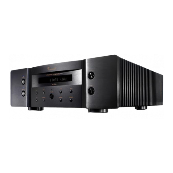
I I N N C C L L U U D D E E D D I I N N D D E E L L I I V V E E R R Y Y The SV-234 is the most versatile integrated stereo amplifier from the Vincent range. - Page 27 1. SPEAKER A/B If suitable speakers are used, a second pair of speakers can be operated at the same time. This button allows each of the speaker pairs (designated A and B) to be individually switched on and off. The LED located above each of the buttons shows which of the speaker pairs is active.
- Page 28 SPEAKER: Loudspeaker terminals At these output sockets with threaded terminals one or two pair(s) of stereo loudspeakers can be connected. Speaker cable with 4 mm banana plugs can be used. Please take note of the infor- mation given in the section "Installation", if two pairs of loudspeakers will be connected to the amplifier.
-
Page 29: R R E E M M O O T T E E C C O O N N T T R R O O L
Point the front of the remote control directly at the front of the appliance, making sure there are no objects between the remote control and the appliance. The distance between the remote control and the appliance should not be more than 7 m, as the reliability of the remote control is affected beyond this range. - Page 30 B B U U T T T T O O N N S S O O F F T T H H E E R R E E M M O O T T E E C C O O N N T T R R O O L L 17.
-
Page 31: I I N N S S T T A A L L L L A A T T I I O O N
Set up the cable links in a sequence as follows. Connect the power cable between device and power sup- ply only after all other connections have been made. Two loudspeakers, one ore more source devices and the mains cable have to be connected as a minimum. The cables for power control, to recording equipment or to another stereo amplifier must only be connected if they are to be used. - Page 32 They have an identical function and differ only in name. SV-234 C C O O N N N N E E C C T T I I O O N N O O F F O O N N E E A A U U D D I I O O S S O O U U R R C C E E W The "balanced"...
- Page 33 SV-234 SV-234 If the input "LINE5" has been selected, the amplifier SV-234 acts like a stereo power amplifier. If you want the amplifier SV-234 to automatically switch on/off every time the HiFi component connected to "LINE5" is switched on/off, the power control cable connections subsequently described must be applied.
- Page 34 The SV-234 is equipped with one input connector and two output connectors for the power control. As a result, this amplifier can supply and transmit the switching signal for other components in the system as well as accept it from other components.
- Page 35 The output level is independent from the volume setting but reacts to the "MUTE" command. SV-234 Connect this signal output to the signal input ("LINE IN", "TAPE IN" oder "REC IN") on the recording appli- ance using RCA cables.
- Page 36 C C O O N N N N E E C C T T I I O O N N O O F F T T H H E E L L O O U U D D S S P P E E A A K K E E R R S S Either a single speaker pair (A) or two speaker pairs (A+B) can be connected to the SV-234 amplifier.
- Page 37 If you want to use speaker cables equipped with spade lug connectors, every connector screw must be opened by turning counterclockwise. After that, the lug must be moved under the screw head. Then, turn the screw clockwise to fasten the lug to the connector. To avoid damages to the amplifier, make sure the connection is tight and no bare metal from the cable lug connector makes contact with the rear panel or with another terminal.
-
Page 38: O O P P E E R R A A T T I I N N G G T T H H E E A A P P P P L L I I A A N N C C E
O O P P E E R R A A T T I I N N G G T T H H E E A A P P P P L L I I A A N N C C E E O O p p e e r r a a t t i i o o n n B B u u t t t t o o n n ( ( s s ) ) Switch on and off... - Page 39 “PRE OUTPUT” (14). The GAIN-operation is useful, if the combination of amplifier and speaker is so sensitive that the usable region of the volume control of the SV-234 lies at the lowest values. In this situation the volume steps are too coarse.
-
Page 40: T T I I P P S
Burn in/ Warm up Your audio components need a certain time period until they reach maximum performance. The duration of this "warm up" time is very diffe- rent for the various elements of your audio system. Higher and homogeneous sound quality is achie- ved while keeping the device switched on. - Page 41 S S E E A A R R C C H H F F O O R R E E R R R R O O R R S S Symptom Possible Cause Unit does not work Mains cable is not connected to a suitable mains wall outlet.
-
Page 42: T T E E C C H H N N I I C C A A L L S S P P E E C C I I F F I I C C A A T T I I O O N N S
S S y y m m p p t t o o m m P P o o s s s s i i b b l l e e C C a a u u s s e e Front panel display It has been switched off before using "DIMMER"... -
Page 43: G G L L O O S S S S A A R R Y
Audio Sources/Source devices These are the components of your HiFi system and all other appliances, whose sound you want to hear over the system and are thus connected to the pre- amplifier, amplifier or receiver. This includes CD players, DVD players, tuners (radios), cassette play- ers, DAT recorders, personal computers, record players, portable audio devices and many more. -
Page 44: C C O O N N S S I I G G N N E E S S D D E E S S É É C C U U R R I I T T É
C C O O N N S S I I G G N N E E S S D D E E S S E E C C U U R R I I T T E E La construction de cet appareil a été soumise à des contrôles de qualité... - Page 45 Montage de l'appareil Le site de montage de l'appareil a une incidence sur le son. Posez l'appareil uniquement sur une surface appropriée et stable. Pour profiter pleinement du potentiel sonore de votre système, nous vous recommandons de placer les appareils sur des racks Vincent et de ne pas les poser l'un sur l'autre.
-
Page 46: D D E E S S C C R R I I P P T T I I O O N N D D E E L L ' ' A A P P P P A A R R E E I I L L
O O B B J J E E T T D D E E L L A A L L I I V V R R A A I I S S O O N N L’appareil SV-234 est l’amplificateur stéréo le plus polyvalent du programme Vincent. - Page 47 1. SPEAKER A/B : touches de commutation ou de coupure des deux paires de haut-parleurs Avec des haut-parleurs appropriés, on peut aussi utiliser simultanément une deuxième paire de haut-parleurs. Avec ces touches, on peut commuter ou couper séparément chacune des deux paires de haut-parleurs (désignées par A et B).
- Page 48 SPEAKER : bornes de raccordement des haut-parleurs serrage à vis pour le raccordement d’une ou de deux paires de haut-parleurs. On peut utiliser des câbles de haut-parleurs avec fiches banane de 4 mm. Respectez les instructions du chapitre "Installation" dans le cas où deux paires de haut-parleurs doivent être raccordées.
-
Page 49: T T É É L L É É C C O O M M M M A A N N D D E
Orientez la partie avant de la télécommande directement vers la face de l'appareil. Aucun obstacle ne doit se trouver entre la télécommande et l'appareil. La distance entre la télécommande et l'appareil ne doit pas être supérieure à 7m, car la fiabilité de la télécommande diminue au-delà de cette portée. - Page 50 T T O O U U C C H H E E S S D D E E L L A A T T É É L L É É C C O O M M M M A A N N D D E E 17.
-
Page 51: I I N N S S T T A A L L L L A A T T I I O O N
Réalisez les raccordements de câbles dans l’ordre préconisé ci-dessous. Raccordez d’abord le cordon sec- teur à l’appareil, puis branchez-le à la prise du secteur. Il faut dans tous les cas, raccorder deux haut-par- leurs, un ou plusieurs appareils source ainsi que le cordon secteur. Les câbles pour la commande de mise sous tension, de l’appareil d’enregistrement ou pour une autre amplification de puissance stéréo ne doivent être raccordés que s’ils sont nécessaires. - Page 52 SV-234 R R A A C C C C O O R R D D E E M M E E N N T T D D ’ ’ U U N N A A P P P P A A R R E E I I L L S S O O U U R R C C E E A A V V E E C C L L A A S S O O R R T T I I E E S S T T E E R R E E O O - - X X L L R R L’entrée "BALANCED"...
- Page 53 Laissez l’entrée "LINE 5" libre, si vous ne voulez pas utiliser l’amplificateur SV-234 comme étage de sortie. L L I I A A I I S S O O N N S S C C A A B B L L E E E E S S P P O O U U R R L L A A C C O O M M M M A A N N D D E E D D E E M M I I S S E E S S O O U U S S T T E E N N S S I I O O N N ( ( P P O O W De nombreux systèmes AV se composent de nombreux composants individuels.
- Page 54 "POWER CONTROL OUTPUT" ou "TRIG- GER OUTPUT" de cet appareil doit être reliée avec l’entrée du signal de mise sous tension du SV-234 (15). D’autres sorties Trigger des composants AV et les deux sorties de "POWER CONTROL" du SV-234 peuvent alors être reliées à...
- Page 55 Le niveau de sor- tie est indépendant du réglage du volume, mais réagit à la mise en sourdine (15). SV-234 Reliez pour cela cette sortie de signal par une paire de câbles RCA, à l’entrée du signal (« LINE IN », «...
- Page 56 B B R R A A N N C C H H E E M M E E N N T T D D E E S S H H A A U U T T - - P P A A R R L L E E U U R R S S On peut raccorder à l’amplificateur SV-234, une paire de haut-parleurs (A) ou aussi deux paires de haut- parleurs (A+B).
- Page 57 Si on utilise des câbles avec cosses, il faudra desserrer la molette de fixation en la tournant dans le sens antihoraire, insérer la cosse sous la molette et resserrer celle-ci en la tournant dans le sens horaire. Pour éviter tout dommage, assurez-vous que le branchement est bien serré et qu’aucune partie métallique dénu- dée de la cosse ne soit en contact avec la paroi arrière ou une autre borne de raccordement.
- Page 58 C C O O M M M M A A N N D D E E S S D D E E L L ‘ ‘ A A P P P P A A R R E E I I L L A A c c t t i i o o n n T T o o u u c c h h e e ( ( s s ) ) Mise en marche...
-
Page 59: U U T T I I L L I I S S A A T T I I O O N N D D E E L L ' ' A A P P P P A A R R E E I I L
élevée, que la plage utile de réglage du volume du SV-234 se situe dans des valeurs faibles. Alors le volume est déjà très élevé pour de faibles valeurs de réglage de volume et la progressivité... -
Page 60: C C O O N N S S E E I I L L S
Temps de rodage / échauffement Vos appareils audio demandent un certain temps pour atteindre leurs performances maximales. Ce laps de temps est très différent pour les différents composants de votre système. Vous obtiendrez un son de meilleure qualité et plus homogène en lais- sant l’appareil sous tension. - Page 61 R R E E S S O O L L U U T T I I O O N N D D E E P P R R O O B B L L E E M M E E S S Symptôme Cause possible du défaut Pas de fonctionne-...
-
Page 62: C C A A R R A A C C T T É É R R I I S S T T I I Q Q U U E E S S T T E E C C H H N N I I Q Q U U E E S
S S y y m m p p t t ô ô m m e e C C a a u u s s e e p p o o s s s s i i b b l l e e d d u u d d é é f f a a u u t t L’afficheur de la L’afficheur a été... -
Page 63: L L E E X X I I Q Q U U E
L L E E X X I I Q Q U U E E / / B B O O N N A A S S A A V V O O I I R R Sources audio/lecteurs sources Composants de votre chaîne HiFi et tous les autres appareils dont vous voulez entendre le son par votre système et que vous branchez à... - Page 64 Vincent Bewahren Sie die Kaufquittung zusammen mit der Bedienungsanleitung auf. Die Kaufquittung dient Ihnen als Nachweis für den Beginn der Garantiezeit. Die Seriennummer befindet sich an der Rückseite des Gerätes. Please keep the receipt, store it together with this manual. The receipt is your proof for the beginning of the warranty period.