Advertisement
Quick Links
PCB Module Replacement Instructions for
TracVision
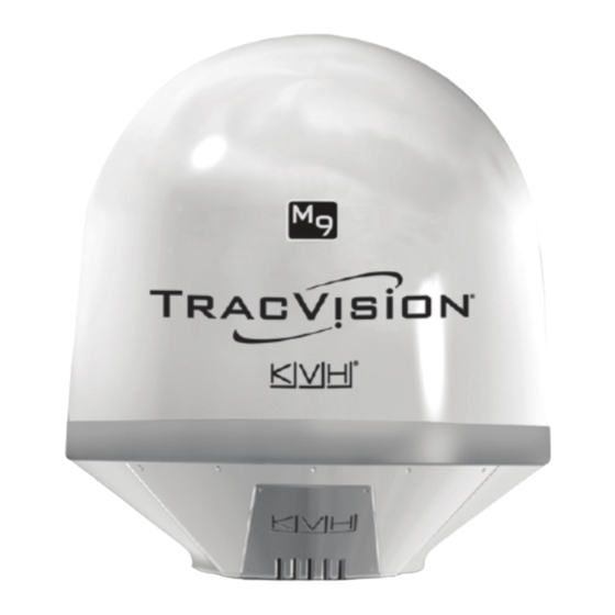
These instructions explain how to replace the PCB module in a TracVision M9 antenna.
IMPORTANT!
Be sure to trim the excess portion of any tie-wraps you install and collect all tie-wrap
trimmings from the antenna to avoid damage when the unit rotates.
Installation Steps
1. Remove the Radome, 2
2. Replace the PCB Module, 2
Tools Required
This procedure requires the following tools:
• Phillips screwdrivers
• Cutting pliers
• 7/16" open-end wrench
Technical Support
If you need technical assistance, please contact KVH Technical Support:
N. America, S. America, Australia:
Phone: +1 401 847-3327
E-mail: techs@kvh.com
KVH, TracVision, and the unique light-colored dome with contrasting baseplate are registered trademarks of KVH Industries, Inc.
All other trademarks are property of their respective companies. The information in this document is subject to change without notice.
No company shall be liable for errors contained herein. © 2008 KVH Industries, Inc., All rights reserved. 54-0530 Rev. A
M9
®
• PC with latest version of the Flash Update
• Digital level (or equivalent)
Europe, Middle East, Asia:
Phone: +45 45 160 180
E-mail: support@kvh.dk
3. Configure the Antenna, 4
4. Reinstall Satellites, 5
Wizard installed
1
Advertisement

Summary of Contents for KVH Industries TracVision M9
- Page 1 All other trademarks are property of their respective companies. The information in this document is subject to change without notice. No company shall be liable for errors contained herein. © 2008 KVH Industries, Inc., All rights reserved. 54-0530 Rev. A...
- Page 2 Step 1 - Remove the Radome Figure 1 Radome Screws Follow the steps below to remove the radome. Radome CAUTION For your own safety, be sure to disconnect power from all wired components before #10-32 Screw (x8) performing this procedure. a.
- Page 3 b. Apply labels to the RF cables connected the Figure 3 RF PCB Connections RF PCB (see Figure 3). You will need to connect each cable to the same connector on the new unit later. Inverter c. Using a 7/16" open-end wrench, disconnect the RF cables connected to the RF PCB (see Cables Figure 3).
- Page 4 Step 3 - Configure the Antenna Figure 5 MCU Maintenance Port Follow the steps below to configure the antenna to use the new PCB module. This procedure requires a PC with the latest version of the Flash Update Wizard installed. Maintenance Port NOTE: If you do not have the KVH Flash Update...
- Page 5 Reinstall the radome. Feed Tube Step 4 - Reinstall Satellites The TracVision M9 system must now be set to track the satellites of your choice. Follow the instructions provided in the TracVision M9 User’s Guide to set the system to track your selected satellites.


