Table of Contents
Advertisement
Quick Links
Advertisement
Table of Contents

Related Manuals for KVH Industries TrackPhone V7


Summary of Contents for KVH Industries TrackPhone V7
- Page 1 TracPhone ® 24" (60 cm) Configuration Installation Guide...
-
Page 2: Table Of Contents
All other trademarks are property of their respective companies. The information in this document is subject to change without notice. No company shall be liable for errors contained herein. © 2008-2010 KVH Industries, Inc., All rights reserved. 54-0464 Rev. E... -
Page 3: Inspect Parts And Get Tools
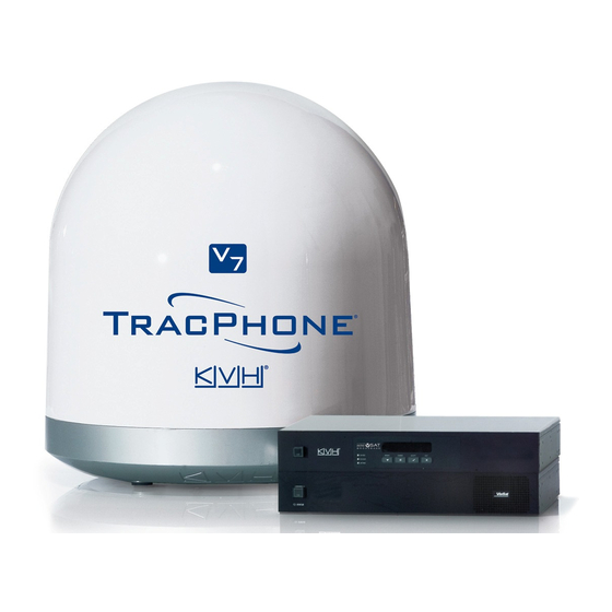
Inspect Parts and Get Tools Before you begin, follow these steps to make sure Figure 1: TracPhone V7 System Components you have everything you need to complete the Antenna installation. a. Unpack the box and ensure it contains everything shown in Figure 1 and on the Kitpack Content Lists. -
Page 4: Plan The Antenna Installation
Plan the Antenna Installation Before you begin, consider the following antenna Figure 2: Blockage from Obstruction installation guidelines: • Minimize blockage. The antenna requires a Blocked! clear view of the sky to transmit and receive 5° to 80° satellite signals (see Figure 2). The fewer Look Angle obstructions, the better the system will Antenna... -
Page 5: Plan The Belowdecks Installation
Plan the Belowdecks Installation Before you begin, consider the following Figure 4: Control Unit or Modem Dimensions (Identical) installation guidelines for the belowdecks units. 2.61" (6.6 cm) Control Unit and Modem • Select a mounting location in a dry, well- ventilated area belowdecks away from any heat sources or salt spray. -
Page 6: Prepare The Belowdecks Units
Prepare the Belowdecks Units Option 1 - Mounting in the Case If you plan to mount the control unit and modem inside the optional 19" (482.6 mm) case, follow Figure 7: Assembling the Case these steps to assemble the case. Top Cover M4 x 12mm Screw (x4) a. - Page 7 Prepare the Belowdecks Units Option 2 - Mounting Units Together If you plan to mount the control unit and modem together as an assembly, without using the optional case or an equipment rack, follow these Figure 10: Attaching the Strain-Relief Bracket steps to attach the strain-relief bracket and “L”...
- Page 8 Prepare the Belowdecks Units Option 3 - Mounting Units Separately If you plan to mount the control unit and modem separately, follow these steps to detach the Figure 12: Detaching the Control Unit from the Modem control unit from the modem, attach the strain- relief brackets, and attach the “L”...
-
Page 9: Prepare The Antenna Site
Prepare the Antenna Site Once you have identified a suitable antenna Figure 15: Antenna Mounting Holes Layout mounting site, according to the guidelines provided in Step 2, follow these steps to drill the mounting holes and cable access hole to prepare the site for installation. -
Page 10: Remove The Restraints
Remove the Restraints Inside the antenna, several shipping restraints Figure 16: Removing the Radome prevent the antenna assembly from moving during shipment. Follow these steps to remove the first set of shipping restraints. a. Remove the six #10-32 Phillips screws securing the radome to the baseplate (see Figure 16). -
Page 11: Wire The Antenna
Wire the Antenna Follow these steps to connect the data, power, Figure 18: RF Cable Requirements and RF cables to the antenna. 15-50 ft (5-15 m) Cable Run a. In addition to the data and power cables, you will need to connect two 75 RF coax cables Cable: RG-11 from the antenna to the belowdecks Connector: SNS11AS... -
Page 12: Mount The Antenna
Mount the Antenna Follow these steps to mount the antenna to the Figure 20: Forward Arrow in Antenna Baseplate mounting surface. a. Place the antenna baseplate over the holes drilled in the mounting surface. b. Make sure the forward arrow inside the baseplate points toward the bow and is parallel to the vessel’s centerline (see Figure 20). -
Page 13: Wire The Belowdecks Units
Wire the Belowdecks Units Wire the Antenna Cables Figure 23: Antenna Power and Data Wiring Follow these steps to connect the antenna to the control unit and the modem. Antenna NOTE: A system wiring diagram is provided in Terminal Strip Connector Appendix A on page 27. - Page 14 Continued Wire the Belowdecks Units Wire the Control Unit to the Modem Figure 26: Modem Data and BUC Power Wiring Follow these steps to connect the control unit to Control Unit the modem. Modem BUC Power MODEM BUC POWER RS422 20V 2.5A a.
-
Page 15: Connect Power
Connect Power Follow these steps to connect power to the Figure 29: Power Wiring TracPhone V7 system. Control Unit TIP: To ensure a stable power level, KVH AC Input recommends that you use an uninterruptible power supply (UPS) to power the system. Power Modem a. -
Page 16: Configure The Computer(S)
Configure the Computer(s) Follow these steps to configure the user’s Figure 30: Windows 7/Vista - Local Area Connection Properties computer(s) for a wired connection to the TracPhone V7. Once you have set up and tested a wired connection, you can configure a wireless connection (wireless access point not supplied). - Page 17 Continued Configure the Computer(s) Windows XP Figure 32: Windows XP - Local Area Connection Properties a. Turn on the networked computer. b. At the Windows Contol Panel, double-click Network Connections. You can find the control panel either through the Start menu or “My Computer.”...
- Page 18 Continued Configure the Computer(s) Macintosh OS X Figure 34: Macintosh OS X - Network Preferences a. Turn on the networked computer. b. At System Preferences, click the Network icon. c. At the Network window (see Figure 34), select the following: •...
-
Page 19: Turn On The System
Turn On the System Follow these steps to turn on the TracPhone V7 Figure 35: Power Switches system for the first time. Power Switch Control Unit a. Ensure the antenna has a clear, unobstructed view of the sky. b. Apply vessel power to the TracPhone system, including the switch, MTA, and remote Power Switch Modem... -
Page 20: Update The System Software
Update the System Software If Necessary Follow these steps to ensure the latest software is installed in the TracPhone V7 system. Figure 37: Software Versions Displayed on the Control Unit a. At the control unit, press MENUS until the display shows “ANTENNA STATUS” (see Figure 37). -
Page 21: Set Up Rf Hazard Zones
Set Up RF Hazard Zones Optional To prevent exposure to RF energy, which may be harmful to people who stand within 36 feet Figure 39: Example of an RF Radiation Hazard Zone (11 meters) of the antenna, you can configure up to two RF radiation hazard zones for areas where RF Radiation crew and/or passengers frequent (see Figure 39). -
Page 22: Test The System
Test the System Now that you have installed the system, you can Figure 42: Good Service Connection Indicated on Control Unit LCD test the system to verify it is ready for customer delivery. Follow these steps to test the system for proper operation. - Page 23 Continued Test the System g. Open the web browser on any wired (not Figure 45: General Status Page Via Modem Web Interface wireless) networked computer and enter the following address to access the modem’s web interface: http://192.168.0.1 h. Under “Forward Link” on the General Status page, make sure Eb/No is at least 2 dB (see Figure 45).
-
Page 24: Educate The Customer
Educate the Customer The installation is complete! Before you leave the Figure 46: Customer Welcome Kit vessel, enter the system serial numbers on the first page of the User’s Guide, give the Welcome Kit to the customer, and review the following with the customer: •... - Page 25 Appendices This section provides a system wiring diagram and supplemental instructions for terminating an LMR-400-75 cable. Contents A. Wiring Diagram ........27 B. Terminating LMR-400-75 Cable ..28...
-
Page 26: Wiring Diagram
Wiring Diagram Appendix Antenna Terminal Strip Connector Note: Terminals #3 and #8 are not used Power Black Data White/Gray Gray/White White/Orange Orange/White White/Brown Brown/White White/Blue Blue/White Control Unit Power GP10 Serial Service Module Power Power Antenna On/Off Audio Modem BUC PWR USER AC PWR Rx RF... - Page 27 Terminating LMR-400-75 Cable Appendix These instructions explain how to terminate an Figure 49: Cutting the Cable LMR-400-75 RF cable with an EZ-400-FMH-75 “F” connector using the tools from the TK-400EZ-75 tool kit. For more detailed instructions, refer to the Times Microwave website (www.timesmicrowave.com).
- Page 28 Continued Terminating LMR-400-75 Cable 5. Using a utility knife, carefully remove any Figure 53: Removing Plastic Residue residual plastic from the center conductor, if necessary (see Figure 53). 6. Insert the end of the cable into the #2 end of the ST-400EZ stripping tool (see Figure 54).
- Page 29 Continued Terminating LMR-400-75 Cable 8. Gently flare the braid with your fingers (see Figure 57: Flaring the Braid Figure 57). 9. Insert the end of the cable into the connector body until the dielectric is firmly seated inside the connector (see Figure 58). Be sure all braid wires remain on the outside of the connector.
- Page 30 Continued Terminating LMR-400-75 Cable 12. Using an appropriate crimp tool (either the Figure 61: Crimping the Ferrule onto the Cable CT-400/300 or the HX-4 with Y1719 dies), crimp the ferrule in place (see Figure 61). Crimp as close to the connector body as possible.
- Page 31 KVH Industries, Inc. KVH Europe A/S 50 Enterprise Center • Middletown, RI 02842-5279 • U.S.A. Kokkedal Industripark 2B • 2980 Kokkedal • Denmark Phone: +1 401 847-3327 • Fax: +1 401 849-0045 Phone: +45 45 160 180 • Fax: +45 45 160 181 E-mail: info@kvh.com...